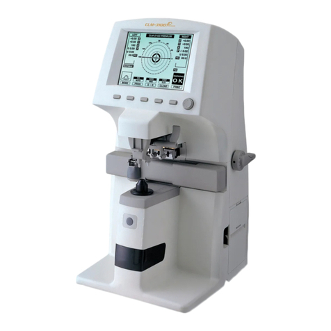
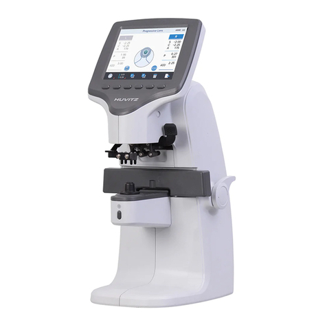
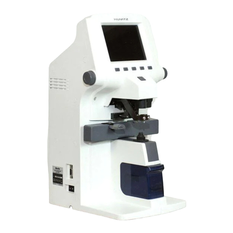
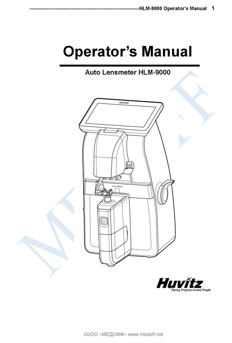
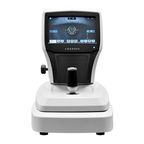
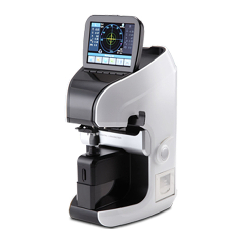
Huvitz HLM-9000 User manual


Auto Lensmeter HLM-9000
1
Service Manual
Auto Lensmeter HLM-9000

2
AUTO-LENSMETER
INDEX
1. INTRODUCTION......................................................................................................................... 4
1.1. COMPONENTS LIST ............................................................................................................................................4
1.2. REPAIR PROCEDURE............................................................................................................................................6
1.3. CAUTIONS ............................................................................................................................................................7
1.4. SOFTWARE OS VERSION ...................................................................................................................................7
1.5. OPTICAL SYSTEM ................................................................................................................................................7
1.6. MEASUREMENT PRINCIPLE ................................................................................................................................9
2. CHECKING AND SETUP METHOD........................................................................................ 10
2.1. SETUP ORDER................................................................................................................................................... 10
2.2. HOW TO SET ORIGIN...................................................................................................................................... 11
2.3. HOW TO SET 12 STANDARD LENSES ............................................................................................................ 12
2.4. HOW TO SET PRISM........................................................................................................................................ 13
2.5. THE CALIBRATION OF THE CYLINDRICAL AXIS .............................................................................................. 14
2.6. PD SETUP ......................................................................................................................................................... 16
2.7. UV &BLUE SETUP ........................................................................................................................................ 16
2.8. DIOPTER SETTING VARIABLES LIST................................................................................................................ 19
2.9. HOW TO CHANGE THE CCD CAMERA ......................................................................................................... 20
2.10. HOW TO CHANGE THE LED ASSEMBLY................................................................................................... 22
2.11. HOW TO CHANGE THE PINHOLE HOUSING............................................................................................ 23
3. REPAIR STANDARD .................................................................................................................... 24
3.1. REMOVING COVER ASSEMBLY ........................................................................................................................ 24
3.2. LCD ASS’Y........................................................................................................................................................ 26
3.3. PRINTER ASS’Y................................................................................................................................................. 28
3.4. B4_BACK-BONE-ASSEMBLY....................................................................................................................... 30
3.4.1. PD-Bar subassembly........................................................................................................................ 32
3.5. B4_FRAME-TOTAL- ASSEMBLY .................................................................................................................. 34
3.6. B4_UV-BONE-ASSEMBLY............................................................................................................................. 36
3.6.1. B4_FOOT-FRAME-Subassembly.................................................................................................. 38
3.6.2. B4_PEN-FRAME-ASSY ..................................................................................................................... 40
Auto Lensmeter HLM-9000
3
3.7. B4_PEN-SLIDE- ASSEMBLY.......................................................................................................................... 42
3.8. PD-PINION-ASSEMBLY................................................................................................................................. 44
3.9. B4_FRAME-ASSEMBLY .................................................................................................................................. 46
3.9.1. Removing Lens housing bone and LED subassembly.................................................. 48
4. ELECTRICAL BLOCK DIAGRAM.............................................................................................. 50
4.1. ELECTRICAL BLOCK DIAGRAM......................................................................................................................... 50
4.2. INSPECTING SMPS.......................................................................................................................................... 52
4.3. LCD TEST........................................................................................................................................................ 53
4.4. LED TEST......................................................................................................................................................... 53
4.5. UV &BLUE MODULE TEST..................................................................................................................... 54
4.6. PD TEST........................................................................................................................................................... 55
4.7. THERMAL PRINTER TEST......................................................................................................................... 56
5. HOW TO UPGRADE THE OS PROGRAM ............................................................................. 57
5.1. INTRODUCTION ................................................................................................................................................ 57
5.2. HOW TO UPGRADE THE OS PROGRAM USING DLP APPLICATION IN HLM MACHINES..................... 58

4
AUTO-LENSMETER
1. Introduction
1.1. Components List
Figure 1. Components Names (I)
Touch LCD Screen
MEM Button
(Save Button)
Marking Lever
Lens Table Lever
Lens Table
UV, Blue Cover
Lens Holder Lever
Lens Cap
PD Sensor
Printer

Auto Lensmeter HLM-9000
5
Figure 2. Components Names (II)
Figure 3. Components Names (III)
Power Switch
Power Connector
USB Connector
RS-232 Connector

6
AUTO-LENSMETER
1.2. Repair Procedure
Power ON
1. Examining the Internal
Components First
2. Inspecting The value,
S.C.A. Prism
Checking
Abnormal
State
Cleaning the
Pinhole
Power off and on
Checking
Abnormal
State
Setup Again
Exit
Normal
State
Normal
State
Figure 4. Repair procedure flow chart

Auto Lensmeter HLM-9000
7
1.3. Cautions
Always protect this instrument with Dust Cover after using.
Do not vibrate or drop this instrument; it can cause damage.
Use soft cloth or cotton swaps with alcohol when clean the pinhole.
1.4. Software OS version
Software OS version will be shown on the screen if you turn on the power switch.
1.5. Optical System
Optical system resolves the features of the lens such as diopter and prism. It is composed
of light emitting part and signal receiving part: light emitting part composed of optic LED
and collimation lens, signal receiving part composed of hartman plate and 2-dimentional
CMOS sensor. The followings are the components of each part:
Light Emitting Part
- Optic LED : 545nm
- Ball Lens : condenses the light radiated from Optic LED.
- Rubber Ring : fix ball lens.
- Scatter : disperse the optic LED light
- Pinhole : 0.3mm diameter
- Collimation lens : makes parallel light.

8
AUTO-LENSMETER
Signal Receiving Part
- Hartmann plate : divide the signal into 81 points. Prevent the other light except the
signal
- 2-dimentional CMOS sensor : converts signals into digital value.
The lens meter also built optical system for UV and Blue light transmittance. The system is
composed of light emitting LED (UV and Blue light) and receiving part (UV and Blue
detector). The wavelength of the UV light is 395nm and the Blue is 450 nm.

Auto Lensmeter HLM-9000
9
1.6. Measurement Principle
Basic Principle
When there is no lens (0D state), parallel light that has transmitted the collimator lens
passes the pinhole and makes image on CCD. In case of convex lens (lens with plus
diopter), parallel light that has transmitted the collimator lens converges through the
measuring lens, passes the pinhole and then makes image on CCD. On the other hand, in
case of concave lens (lens with minus diopter), parallel light that has transmitted the
collimator lens diverges through the measuring lens and then passes the pinholes and at
last makes image on CCD.
Initial State
Concave Lens
Convex Lens

10
AUTO-LENSMETER
2. Checking and Setup Method
2.1. Setup Order
After booting is completed, you can see button icons in bottom area. To enter the ‘SETUP’
mode, see as follows:
A. Press once delete button (trash icon).
B. Press three times S or R side (data area).
C. Press the user setup (option) button.
HLM-9000 will start in setup mode. While this mode, ‘SETUP’ mark will show in the left-
upper area.
Calibration can be processed only in SETUP mode; LENS, PRISM, CYLINDER, PD,
UV&BLUE. To all setting, you should convert the display step (STEP) into 0.01. In case of
prism, convert the prism display into P-B format. Display step (STEP) and prism display
format can be changed in ‘User Setup’ screen. Press the ‘USER’( ) button in the
basic display screen.

Auto Lensmeter HLM-9000
11
2.2. How to Set Origin
The steps of setting origin are as follows:
A. Press the ‘LENS’( )button.
B. Press the ‘MEASURE’button.
C. Determine the lens to measure by using two ‘-INDEX’, ’+INDEX’ buttons.
D. ‘D-0.01’ button and ‘D+0.01’ button by the given value in the standard model-eye
specification.
E. To save and exit, press the ‘SAVE’ button.
F. Press the ‘EXIT’ button again. And check if the diopter that has been set up in the
basic display screen is shown.
‘SAVE SCREEN INFORMATION’ is as follows:
If you want to return to the previous one without saving in the SAVE screen, press the
rightmost ‘PREV’ button.
CEN: The x, y, coordinates of big center point.
LEN: Average distance between of four points.
CON: The x, y, coordinates of four big points.
DIP: Saving order and the saved diopter.
Buttons for Selecting
Diopter
Buttons for Calibrate
Diopter
SAVE button
Previous screen
button

12
AUTO-LENSMETER
2.3. How to Set 12 standard lenses
If the measured value is not accurate, you should set the diopter variables again by using
the standard lens-set: for all the 12 lenses in the standard lens set. Always keep the
standard lens clean out of dust or stain.
A. Set the diopter display step into 0.01.
B. Place the standard lens and move it so that ‘Green Color Cross Line’ will appear.
C. Press the ‘LENS’ ( ) button.
D. Press the ‘MEASURE’ button.
E. Determine the lens to measure by using two ‘-INDEX’, ’+INDEX’ buttons.
F. ‘D-0.01’ button and ‘D+0.01’ button by the given value in the standard model-eye
specification.
G. To save and exit, press the ‘SAVE’ button.
H. Press the ‘EXIT’ button again. And check if the diopter that has been set up in the
basic display screen is shown. .
I. Repeat the procedures from step B to H for 12 standard lenses.
The information displayed in the ‘Setting Diopter’ screen is the same as that of ‘Setting
0D’ screen.

Auto Lensmeter HLM-9000
13
2.4. How to Set Prism
If the measured value is not accurate, you should set the 2, 5, 10, 15, 20lens again
by using the standard lens-set.
A. First, convert prism display format into P-B.
B. Then, press the ‘PRISM’ ( ) button.
C. After selecting the 2lens from the standard lens set, place it on the lens cap.
D. ‘D-0.01’ button and ‘D+0.01’ button by the given value in the standard model-eye
specification.
E. Rotate it to become the center position of 0~30(A0) degree.
F. Press the ‘MEASURE’ button and check if ‘A0/A1/A2/A3/A4/A5/A6/A7/A8/A9/A10/
A11:’value is changed.
G. Repeat from step E ~ F to the center position of 331 ~ 360(A11) degree.
H. Finally the ‘SAVE’ button to save.
I. Repeat the procedures from C to H for 5, 10, 15lens and 20lens.
‘Prism’ screen will show the following information:
-PRISM : 2 Prism, 5 Prism, 10 Prism, 15 Prism, 20 Prism
-Idx : Display prism index currently.
-ANGLE : Display axis index currently.

14
AUTO-LENSMETER
ANGLE
PRISM BASE
0
0°~ 30°center
1
31°~ 60°center
2
61°~ 90°center
3
91°~ 120°center
4
121°~ 150°center
5
151°~ 180°center
6
181°~ 210°center
7
211°~ 240°center
8
241°~ 270°center
9
271°~ 300°center
10
301°~ 330°center
11
331°~ 360°center
2.5. The calibration of the cylindrical axis
With the +5D rectangular cylindrical lens, we can calibrate the cylindrical axis of our
machine. The procedures are as followings:
A. First, convert prism display format into P-B.
B. Then, press the ‘CYLINDER’ ( ) button.
C. Place the +5D rectangular cylindrical lens on the lens cap.

Auto Lensmeter HLM-9000
15
D. ‘-0.01’ button and ‘+0.01’ button by the given value in the standard model-eye
specification.
E. Locate it to the center while cling it to the lens.
(Axis : 90°/135°/180°/45°, Prism_x, y: 0)
F. Press the ‘MEASURE’ button and check if ‘A90/A135/A180/A45:’ value is changed.
G. Rotate the cylinder lens with a, repeat from Step D ~ to Step E to the Axis value
equal to 135°/180°/45°.
H. Finally the ‘SAVE’ button to save.
- CYLINDER : 5Diopter cylinder lens.
- Idx : Display axis index currently.
- AXIS : Display axis base currently.

16
AUTO-LENSMETER
2.6. PD Setup
With the PD Sensor, we can calibrate the PD value of our machine.
The procedures are as followings:
A. Press the ‘PD’( ) button.
B. Push in the PD sensor is the leftmost. And press the ‘L Lim’ button.
C. Push in the PD sensor is the rightmost. And press the ‘R Lim’ button and check if
‘PD POSITION[0] ~ PD POSITION[8]’values are changed.
D. Finally the ‘SAVE’ button to save.
The information displayed in ‘setting the position of PD’ screen is as follows:
2.7. UV & BLUE Setup
With the UV&BLUE, we can calibrate the UV&BLUE value of our machine.
The procedures are as followings:
A. Press the ‘UV&BLUE’( ) button.
B. Open UV&BLUE cover.
C. Focus to UV 0.0 by using ‘INDEX’ button.

Auto Lensmeter HLM-9000
17
D. ‘-0.01’button and ‘+0.01’ button by the given value in the UV lens specification.
E. When UV transmissivity is 0.0 : Prevent part that UV-LED comes out.
When UV transmissivity is 25.0/50.0/75.0 : Put a lens on the top of the UV-LED
comes out..
When UV transmissivity is 100.0 : Nothing raises.
F. Press the ‘MEASURE’ button.
G. UV transmissivity by 0.0->25.0->50.0->75.0->100.0 orders Step C ~ to Step F repeat.
H. Focus to BLUE 0.0 by using ‘INDEX’ button.
I. ‘-0.01’button and ‘+0.01’ button by the given value in the BLUE lens specification.
J. When BLUE transmissivity is 0.0 : Prevent part that BLUE-LED comes out.
When BLUE transmissivity is 25.0/50.0/75.0 : Put a lens on the top of the BLUE-LED
comes out.
When BLUE transmissivity is 100.0 : Nothing raises.
K. Press the ‘MEASURE’ button.
L. BLUE transmissivity by 0.0->100.0->25.0->50.0->75.0 orders Step C ~ to Step F
repeat.
M. Finally the ‘SAVE’ button to save.
N. Press the ‘EXIT’ button and get out.
The information displayed in ‘setting the position of UV’ screen is as follows:
The information displayed in ‘setting the position of BLUE’ screen is as follows:

18
AUTO-LENSMETER

Auto Lensmeter HLM-9000
19
2.8. Diopter Setting Variables List
The followings are diopter setting variables list:
If diopter controlling is performed normally, the length of each row (L) decreases row by
row.
WAVEFRONT DATA INFORMATION [ALL DIOPTER]
0 [-25.01]: L=+174.59; 123.46, 123.45: average distance and distance rates between
the four points and -25D
1 [-19.99]: L=+168.28; 118.99, 119.00: average distance and distance rates between
the four points and -20D
…
6 [+0.00]: L=+136.08; 96.32, 96.12 CX:640.58: average distance and distance rates
between the four points and 0D
7 [+2.50]: L=+131.20; 92.83, 92.71 CY:510.24: average distance and distance rates
between the four points and +2.5D
…
12 [+25.00]: L=+73.53; 52.09, 51.90: average distance and distance rates between
the four points and +25.00D
Other manuals for HLM-9000
2
Table of contents
Other Huvitz Measuring Instrument manuals

Huvitz
Huvitz CRK-8800 User manual

Huvitz
Huvitz HT-5000 User manual

Huvitz
Huvitz CLM-3100P User manual

Huvitz
Huvitz HLM-7000 User manual

Huvitz
Huvitz HLM-1 User manual

Huvitz
Huvitz HBM-1 User manual

Huvitz
Huvitz HRK-8000A User manual

Huvitz
Huvitz CR-9000 User manual

Huvitz
Huvitz HNT-1 User manual

Huvitz
Huvitz HRK-9000A User manual

Huvitz
Huvitz HLM-1 User manual

Huvitz
Huvitz CLM-7000 User manual

Huvitz
Huvitz HNT-1 User manual

Huvitz
Huvitz HRK-1 User manual

Huvitz
Huvitz CLM-9000 User manual

Huvitz
Huvitz HLM-9000 User manual

Huvitz
Huvitz CLM-3100P User manual

Huvitz
Huvitz CLM-4000 User manual

Huvitz
Huvitz HLM-7000P User manual

Huvitz
Huvitz CRK-1 User manual