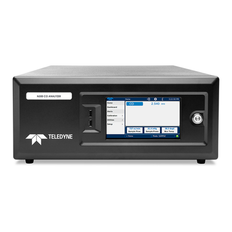
Teledyne API – Model T300/T300M CO Analyzer Table of Contents
xi
11.1.2. Fault Diagnosis with TEST Functions................................................................................................240
11.1.3. the Diagnostic Signal I/O Function ....................................................................................................243
11.1.4. Status LEDs.......................................................................................................................................245
11.1.4.1. Motherboard Status Indicator (Watchdog) .................................................................................245
11.1.4.2. Sync Demodulator Status LEDs.................................................................................................246
11.1.4.3. Relay Board Status LEDs...........................................................................................................247
11.2. Gas Flow Problems .................................................................................................................................249
11.2.1. T300/T300M Internal Gas Flow Diagrams.........................................................................................250
11.2.2. Typical Sample Gas Flow Problems..................................................................................................253
11.2.2.1. Flow is Zero................................................................................................................................253
11.2.2.2. Low Flow ....................................................................................................................................254
11.2.2.3. High Flow....................................................................................................................................254
11.2.2.4. Displayed Flow = “Warnings” .....................................................................................................255
11.2.2.5. Actual Flow Does Not Match Displayed Flow ............................................................................255
11.2.2.6. Sample Pump.............................................................................................................................255
11.3. Calibration Problems ...............................................................................................................................255
11.3.1. Miscalibrated......................................................................................................................................255
11.3.2. Non-Repeatable Zero and Span........................................................................................................256
11.3.3. Inability to Span – No SPAN Button (CALS)......................................................................................256
11.3.4. Inability to Zero – No ZERO Button (CALZ).......................................................................................256
11.4. Other Performance Problems..................................................................................................................257
11.4.1. Temperature Problems......................................................................................................................257
11.4.1.1. Box or Sample Temperature......................................................................................................257
11.4.1.2. Bench Temperature....................................................................................................................257
11.4.1.3. GFC Wheel Temperature...........................................................................................................258
11.4.1.4. IR Photo-Detector TEC Temperature.........................................................................................259
11.4.2. Excessive Noise.................................................................................................................................259
11.5. Subsystem Checkout...............................................................................................................................260
11.5.1. AC Mains Configuration.....................................................................................................................260
11.5.2. DC Power Supply...............................................................................................................................261
11.5.3. I2C Bus...............................................................................................................................................261
11.5.4. Touchscreen Interface.......................................................................................................................262
11.5.5. LCD Display Module ..........................................................................................................................262
11.5.6. Relay Board .......................................................................................................................................262
11.5.7. Sensor Assembly...............................................................................................................................263
11.5.7.1. Sync/Demodulator Assembly.....................................................................................................263
11.5.7.2. Electrical Test.............................................................................................................................263
11.5.7.3. Opto Pickup Assembly ...............................................................................................................264
11.5.7.4. GFC Wheel Drive .......................................................................................................................264
11.5.7.5. IR Source....................................................................................................................................264
11.5.7.6. Pressure/Flow Sensor Assembly ...............................................................................................265
11.5.8. Motherboard.......................................................................................................................................266
11.5.8.1. A/D Functions.............................................................................................................................266
11.5.8.2. Test Channel / Analog Outputs Voltage.....................................................................................266
11.5.8.3. Analog Outputs: Current Loop....................................................................................................267
11.5.8.4. Status Outputs............................................................................................................................268
11.5.8.5. Control Inputs – Remote Zero, Span..........................................................................................268
11.5.9. CPU....................................................................................................................................................269
11.5.10. RS-232 Communications.................................................................................................................269
11.5.10.1. General RS-232 Troubleshooting.............................................................................................269
11.5.10.2. Troubleshooting Analyzer/Modem or Terminal Operation .......................................................270
11.5.11. The Optional CO2Sensor ................................................................................................................270
11.6. Repair Procedures...................................................................................................................................271
11.6.1. Repairing Sample Flow Control Assembly ........................................................................................271
11.6.2. Removing/Replacing the GFC Wheel................................................................................................272
11.6.3. Checking and Adjusting the Sync/Demodulator, Circuit Gain (CO MEAS) ......................................274


