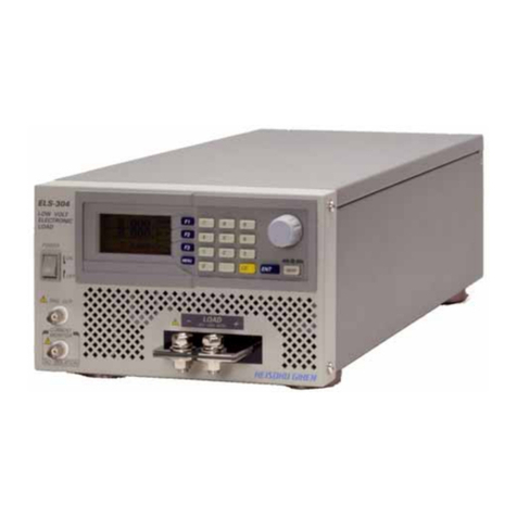
AE SW6 User manual


CONTENTS
1 OVERVIEW............................................................................................................. 1
1.1 SPECIFICATIONS ................................................................................................... 1
1.2 FEATURES ............................................................................................................2
1.3 INCLUDED COMPONENTS &PROBE SELECTION ..................................................2
2 INTRODUCTION OF THE GAUGE AND BASIC OPERATION ....................................... 3
2.1 THE MAIN UNIT .................................................................................................... 3
2.2 KEYPAD................................................................................................................. 3
2.3 BASIC OPERATION ................................................................................................ 4
2.3.1 INITIAL SETUP ............................................................................................... 5
2.3.2 MAKING MEASUREMENTS............................................................................ 6
3 CALIBRATIONS ....................................................................................................... 6
3.1 ZERO CALIBRATION............................................................................................... 7
3.2 MATERIAL VELOCITY CALIBRATION....................................................................... 7
3.2.1 ONE POINT CALIBRATION.............................................................................. 7
3.2.2 TWO POINT CALIBRATION............................................................................. 8
3.2.3 SET THE VELOCITY AS A KNOWN VELOCITY .................................................. 8
4 FUNCTION AND SETUP........................................................................................... 9
4.1 MAIN MENU......................................................................................................... 9
4.1.1 ECHO-ECHO (ECHO-ECHO MEASUREMENT MODE) ...................................... 9
4.1.2 SAVE (DATA PROCESSING) ............................................................................. 9
4.1.3 LIMIT (ALARM MEASUREMENT MODE)...................................................... 12
4.1.4 UNITS .......................................................................................................... 12
4.1.5 SCAN (SCAN MEASUREMENT MODE) ......................................................... 12
4.1.6 DIFF (DIFFERENTIAL MEASUREMENT MODE) ............................................. 13
4.1.7 HTEM (HIGH TEMPERATURE MEASUREMENT MODE)................................ 13
4.1.8 AVG (AVERAGE MEASUREMENT MODE) ..................................................... 14
4.1.9 STD (STANDARD MEASUREMENT MODE) ................................................... 15
4.1.10 RESL (DISPLAY RESOLUTION)..................................................................... 15

4.1.11 RATE (MEASUREMENT RATE).................................................................... 15
4.1.12 AUTO-OFF ................................................................................................. 16
4.1.13 RESET ........................................................................................................ 16
4.1.14 CONTR (DYNAMIC CONTRAST).................................................................. 16
4.1.15 LANGUAGE................................................................................................ 16
4.1.16 PROBE-ZERO-CAL ...................................................................................... 17
4.1.17 MANU-SELECT-PRB (MANUALLY SELECT PROBE) ...................................... 17
4.1.18 SOUND (SOUND SETUP)............................................................................ 17
4.1.19 ROTATE (SCREEN ROTATE) ......................................................................... 17
4.1.20 CAL-1 (ONE-POINT CALIBRATION)............................................................. 17
4.1.21 CAL-2 (TWO-POINT CALIBRATION)............................................................ 17
4.1.22 VELOCITY PRESET (VELOCITY TABLE)......................................................... 18
4.1.23 BACK-LIGHT............................................................................................... 18
4.1.24 DIM (PIPE-WALL MEASUREMENT MODE)................................................. 19
5 APPLICATION NOTES............................................................................................ 19
5.1 FACTORS AFFECTING PERFORMANCE AND ACCURACY ...................................... 19
5.1.1 SURFACE CONDITION .................................................................................. 19
5.1.2 PROBE POSITIONING/ALIGNMENT ............................................................. 19
5.1.3 CALIBRATION............................................................................................... 20
5.1.4 TAPERING& ECCENTRICITY.......................................................................... 20
5.1.5 ACOUSTIC PROPERTIES OF THE MATERIAL.................................................. 20
5.2 PROBE SELECTION .............................................................................................. 21
5.3 HIGH TEMPERATURE MEASUREMENTS.............................................................. 21
6 MAINTENANCE AND TROUBLE SHOOTING........................................................... 23
6.1 ROUTINE CARE AND MAINTENANCE..................................................................23
6.2 PROBES............................................................................................................... 23
6.3 OTHER ERROR OR PROBLEM INDICATIONS.........................................................23
6.3.1 TURN ON AND LOW BATTERY PROBLEMS................................................... 23
6.3.2 COUPLING PROBLEMS ................................................................................ 23
6.3.3 IDENTIFY PROBE PROBLEM......................................................................... 24
6.3.4 MEASUREMENT PROBLEMS........................................................................ 24

1
1 OVERVIEW
Thank you for using QingCheng’s Ultrasonic Thickness Gauge. Please read the operating manual in detail
before use as this will enable you to use the gauge in the shortest amount of time. The manual includes
information on the functions, specifications, settings, operation and calibration of the gauge.
1.1 SPECIFICATIONS
SW6/SW6U: large range, high resolution mode, measuring range of 0.65mm~500mm, display resolution
of 0.01mm, capacity for data storage.
SW7: large range, high resolution mode, through-coat mode, measuring range of 0.65mm~500mm
(standard), 3.0~50mm (through-coat mode), display resolution of 0.01mm.
Table 1-1: SPECIFICATIONS
SW6
SW7
M
ea
s
u
r
i
ng
R
ange
(
S
t
anda
r
d
)
0
.
65
~
500
mm
M
ea
s
u
r
i
ng
R
ange
(
E
c
ho
-
E
c
ho
)
-
3
.
0
~
50
.
0
mm
(
Steel
,
depend
on
probe)
Lo
w
L
i
m
i
t
o
f
P
i
pe
(
P
i
pe
W
a
ll
)
Φ
15
mm
×
1
.
0
mm
(
7
.
5
M
H
z
,
Φ
6
mm
)
Φ
10
mm
×
1
.
2
mm
(
7
.
5
M
H
z
,
Φ
6
mm
)
D
i
s
p
l
a
y
R
e
s
o
l
u
t
i
on
0
.
01
mm
/
0
.
001
i
n
c
h
M
a
t
e
r
i
a
l
V
e
l
o
c
i
t
y
509
~
18699
m
/
s
M
ea
s
u
r
e
m
en
t
R
e
s
o
l
u
t
i
on
±
(
0
.
5
%
H
+
0
.
05
)
mm
B
and
w
i
d
t
h
1
M
H
z~
10
M
H
z
(-
3d
B
)
M
ea
s
u
r
i
ng
R
a
t
e
2
~
20
t
i
m
e
s
/
s
e
c
(
op
t
i
ona
l
)
P
o
w
e
r
S
upp
l
y
3
V
DC
(
t
w
o
AA
ba
tt
e
r
i
e
s
)
W
o
r
k
T
i
m
e
280
H
(
au
t
o
)
100
H
(
ba
ck
li
gh
t
on
)
S
c
r
een
128×64 LCD
S
i
z
e
136
(
L
)
×
72
(
W
)
×
20
(
H
)
mm
W
e
i
gh
t
176g
(
i
n
c
l
ude
ba
tt
e
r
y
)
W
o
r
k
T
e
m
pe
r
a
t
u
r
e
-
10
~
﹢
50
℃
(
w
i
t
h
h
i
gh
t
e
m
pe
r
a
t
u
r
e
p
r
obe
,
up
t
o
300
℃
)

2
W
o
r
k
H
u
m
i
d
i
t
y
20%~90%RH
1.2 FEATURES
●Measuring ranges from 0.65mm to 500mm (dependent on the gauge, probe and material).
●Suitable for different types of probes.
●Material velocity can be chosen or inputted directly. An unknown velocity can be found automatically
by one-point or two-point velocity calibration.
●Numerous kinds of measurement modes: standard, scan, alarm, difference, high-temperature (match
high-temperature probe), average, pipe-wall, echo-echo.
●Special pipe wall measurement mode improves the measuring accuracy of curved surfaces.
●Auto-matching makes the gauge suitable for various materials including metal, glass, plastic, rubber
and gray cast.
●High-capacity data storage (the U model) for up to 2000 data sets.
●Normal measurement can be done using function keys without need to open menu.
1.3 INCLUDED COMPONENTS & PROBE SELECTION
Table 1-2: INCLUDED COMPONENTS
Product
Quantity
Note
Main Unit
1
Probe
1
Couplant
1
Battery
2
USB cable
1
Optional
PC software
1
Optional
Table 1-3: PROBE SELECTION
Probe Type
Measuring Range
Work Temperature
Description
5M,Ф10
0.7~400mm
3.0~50mm(through coat)
-10~+50℃
Basic
(Suitable for through coat)
5M,Ф6
0.70~60mm
-10~+50℃
Little Pipe Wall
2.5M,Ф12
3.0~500mm
-10~+50℃
Basic
7.5M,Ф6
0.65~25mm
-10~+50℃
Mini Pipe Wall
7.5M,Ф10
0.65~250mm
-10~+50℃
High Resolution
ZW5P
4.0~80mm
-10~-300℃
High Temperature
2M,Ф22
3~50mm
(Gray Cast)
-10~+50℃
Gray Cast
Note: Measurement range depends on the probe, material, structure, surface condition and so on. High
temperature tolerance depends on the probe property and couplant.

3
2 INTRODUCTION OF THE GAUGE AND BASIC OPERATION
2.1 THE MAIN UNIT
The main unit of the gauge is shown in Figure 2-1:
Fig. 2-1: The Main Unit
2.2 KEYPAD
The keypad is shown in Figure 2-2:
Fig. 2-2: The Keypad

4
The function of each key is explained below:
•This key is used to: power on the gauge and simultaneously carry out self-checking;
return directly to the measuring GUI when in the menu or sub-menu; power off in the
measuring GUI (long press).
•This key is used to: save or cancel data in the measuring GUI; turn to the next page in
the main menu.
•This key is used to: open the sound velocity table or enter velocity; shift the cursor left
when adjusting readings or when in the main menu.
•This key is used to: open the measurement mode menu; shift the cursor right when
adjusting readings or when in the main menu.
•This key is used to: carry out a one-point calibration for sound velocity in the measuring
GUI; increase the indicated value or shift the cursor up in the main menu.
•This key is used to: carry out a two-point calibration for sound velocity in the measuring
GUI; decrease the indicated value or shift the cursor down in the main menu.
•This key is used to: turn the backlight on or off in the measuring GUI; to confirm your
setup or menu selection.
•This key is used to open the main menu from the measuring GUI or return to the menu.
2.3 BASIC OPERATION
The purpose of this section is to demonstrate how basic measurements can be made with the gauge. The
unit has been shipped from the factory with the following default conditions:
•SOUND VELOCITY: 5900m/s (approximate sound velocity for the steel test bar provided with the
gauge) (see “Note” below)
•BACKLIGHT: ON
•UNITS: mm/inch
•LANGUAGE: ENGLISH

5
•MEASUREMENT RATE: 4 times/s
•DISPLAY RESOLUTION: 0.01mm/0.001inch
A further explanation of these default conditions can be found in later sections of this manual. It is
recommended that they only be changed by the operator after they have become familiar with the more
sophisticated features of the gauge.
Note: The default value for sound velocity is only an approximation of the sound velocity in the test block
material. The sound velocity of stainless steel is typically 5663m/s. Therefore, if you find the default value
gives inaccurate results on your material, please refer to Section 3 for calibration instructions.
2.3.1 INITIAL SETUP
In this section, general operation procedure when in the standard measurement mode will be introduced.
Please follow this procedure when operating the gauge for the first time.
•STEP 1: Plug the probe into the gauge at the top end of the gauge.
•STEP 2: Power on the gauge by pressing . The ON GUI and measuring GUI will appear in
turn (initial setup as shown in Figure 2-3). The gauge will auto-recover the setup from the
previous use.
5920m/s 5.0M STD
10.00mm
Velocity
Probe Frequency
Couple State
Unit
Measurement Mode
Fig. 2-3: Standard Measurement GUI
•STEP 3: Velocity Input or Zero Calibration.
Material velocity must be correct when doing measurements. If the velocity of the material to
be measured is known, please input it first (refer to Section 3.1), otherwise the velocity should
be calibrated. To calibrate the velocity, refer to Section 3.2. Following this, zero calibration
should be carried out (refer to Section 3.1).
•STEP 4: Measurement
Firmly couple the probe to the surface of the material to be measured. Ensure couplant is
applied at the point of contact (refer to Section 2.3.2 for more detail on measurement).

6
•STEP 5: Save
Refer to Section 4.1.2
•STEP 6: Upload data (suitable for USB gauge)
To upload the saved data to the computer for processing, complete the following:
1. Press to enter the main menu (as shown in Figure 4-1)
2. Select SAVE using , , or
3. Press to enter the SAVE GUI01.2.2.2.2.
4. Select UPLOAD using , , or
5. Press to start upload
6. Press to return to the measuring GUI
7. If you want to check the saved data, refer to Section 4.1.2.1
2.3.2 MAKING MEASUREMENTS
•STEP 1: Apply couplant to the test block or material at the spot to be measured. In general, the
smoother the material surface, the thinner the couplant may be. Rough surfaces require more
viscous couplant such as gel or grease. Special couplant may be required for high temperature
applications.
•STEP 2: Press the tip of the probe to the surface of the material to be measured. Use firm
pressure and keep the probe as flat as possible on the material surface.
•STEP 3: Read the material thickness on the gauge display.
Note: For highest accuracy, the velocity of the material must be correct. Refer to Section 3, VELOCITY
SETUP, for this procedure.
3 CALIBRATIONS
Calibration is the process of adjusting the gauge so that it measures accurately on a particular material
using a particular probe at a particular temperature. Calibration should be carried out when using the
gauge for the first time or when probes are changed. Below are the gauge’s various calibration procedures.

7
3.1 ZERO CALIBRATION
If the probe’s zero is not calibrated correctly, all measured values will have a fixed error. When the probe’s
zero is calibrated correctly, the unit can measure the fixed value and correct all subsequent measurements
accordingly. To zero calibrate, follow the below operation:
•STEP 1: Press
MENU
to enter the main menu, select ZERO CAL using ,
CAL-2
,
V-IN
or , and then press
ENTER
. The display will now show INPUT THICKNESS.
•STEP 2: Input material thickness using ,
CAL-2
,
V-IN
or , and press
ENTER
.
•STEP 3: Clean the probe surface and apply couplant to the test block that corresponds with the
inputted thickness.
•STEP 4: Couple the probe to the block and the gauge will automatically return to the measuring
GUI when calibration is completed after a few seconds.
The measured thickness value while coupled to the thin calibration block should be within ±0.20mm of the
correct thickness. If the indicated thickness is two or more times the actual thickness of the thin
calibration block with a good approximate sound velocity, the gauge is “doubling” (ie. measuring to the
2nd or 3rd multiple echo). Do not attempt to do a ‘Zero’ or a ‘Velocity and Zero’ calibration under this
condition. Instead, correct the cause of the doubling before calibrating again: either the calibration block is
thinner than the specified capability of the probe, the probe is malfunctioning, or the gauge is
malfunctioning.
3.2 MATERIAL VELOCITY CALIBRATION
In order for the gauge to make accurate measurements, it must be set to the correct sound-velocity
depending on the material being measured. Different types of materials have different inherent
sound-velocities: for example, the velocity of sound through steel #45 is approximately 5900m/sec,
whereas that of stainless steel is approximately 5663m/sec (a further list of ultrasonic velocities of
common materials can be found in the Appendix 1). If the gauge is not set to the correct sound-velocity, all
of the measurements made by the gauge will be erroneous by a fixed percentage.
3.2.1 ONE POINT CALIBRATION
Material velocity calibration of a material can be done by using a thick test block (with a known thickness)
of that exact material. Calibration must be performed for each new type of material where the sound
velocity is unknown. The procedure is outlined below:

8
•STEP 1: Press to enter the BLOCK THICKNESS GUI.
•STEP 2: Press , , or to input the known thickness of the test block.
•STEP 3: Press to proceed to the next step.
•STEP 4: Clean the probe surface and apply couplant to the test block.
•STEP 5: Couple the probe to the test block and the gauge will return to the measuring GUI
when calibration is completed after 4 seconds.
3.2.2 TWO POINT CALIBRATION
Material velocity calibration of a material can also be completed by using both a thin test block and a thick
test block (with known thicknesses) of that exact material. It requires that the thickness of the material to
be measured be within the range of the thicknesses of the two test blocks. This method can reduce
non-liner error and obtain a result of higher precision. The procedure is outlined below:
•STEP 1: Press to enter the THIN BLOCK GUI.
•STEP 2: Input the thin block’s thickness using , , and .
•STEP 3: Press to enter the THICK BLOCK GUI.
•STEP 4: Input the thick block’s thickness using , , and .
•STEP 5: Press to enter the CAL THIN BLK GUI.
•STEP 6: Clean the probe surface, apply couplant to the thin test block, couple the probe to the
thin test block and when the reading is stable for 4 seconds the gauge will automatically
proceed to the CAL THICK BLK GUI;
•STEP 7: Immediately couple the probe to the thick test block and when the reading is stable for
4 seconds the GUI will display CAL COMPLETE. Following this, the gauge will return back to the
main menu.
3.2.3 SET THE VELOCITY AS A KNOWN VELOCITY
Press to open the velocity table and set the velocity using , and . If the exact

9
velocity of a material is known, you can also press to open the INPUT VELOCITY GUI and directly
input the velocity using , , , and .
Note: Ensure the probe and block are coupled tightly.
4 FUNCTION AND SETUP
4.1 MAIN MENU
Press to open the main menu (shown in Fig. 4-1).
SAVE
LIMIT UNITS SCAN
DIFF HTEM AVG
[SHIFT] Next Page 1
MAIN MENU1
RESL RATE
AUTO-OFF RESET
CONTR LANGUAGE
[SHIFT] Next Page 2
MANU- SELECT-PRB
Sound ROTATE
[SHIFT] Next Page 3
MAIN MENU2
MAIN MENU3
PROBE-ZERO-CAL
ECHO-ECHO
BACK-LIGHT
CAL-2 DIAMETER
Velocity Preset
[SHIFT] Next Page 4
MAIN MENU4
CAL-1
STD
MEASURE MODE:
STD SCAN ALM
DIFF HTEM AVG
DIM ECHO-ECHO
MODE MENU:
Fig. 4-1: Main menus 1-4 and measurement mode menu of the SW7 models
4.1.1 ECHO-ECHO (ECHO-ECHO MEASUREMENT MODE)
If you want to measure a material covered with paint, please select this measurement mode.
4.1.2 SAVE (DATA PROCESSING)
SAVE has five options including CHECK, UPLOAD, DEL-ALL, DEL-GRP, SAVE-SET. Use , ,

10
and to navigate between the options.
4.1.2.1 CHECK
To view your completed measurements, select SAVE in the main menu and then select CHECK
using , , and . The group and serial number can be inputted
using , , and .
4.1.2.2 UPLOAD (suitable for USB gauge)
To transmit all measurement readings to a PC via USB, follow the procedure as below:
•STEP 1: Install the driver on the PC.
•STEP 2: Connect the gauge and the PC with the USB cable.
•STEP 3: Right-click on “My Computer”, select “Manage”, then select “Device Manager”. Find the
port of the connected gauge and remember its name.
•STEP 4: Start “SeriePort.exe” and select the port of the connected gauge.
•STEP 5: Select UPLOAD on the menu of the gauge and press . “CONNECTING” and
“UPLOADING” will be indicated on the display.
•STEP 6: Click “RECEIVE” in the window of SeriePort.exe to transmit all measurement readings to
the PC. When completed, the display of gauge will flash “DONE” and automatically return to
the menu, indicating completed data transmission.
•STEP 7: Click “SAVE” in SeriePort.exe to store the data in the PC (.txt format).
Note 1: If the gauge can’t be powered on normally when it is connected with PC, please disconnect the
gauge and power it on again.
Note 2: If “FAIL TO OPEN THE PORT” is displayed when “RECEIVE” is clicked (in STEP 6), STEP 5 has not
been carried out properly.
Note 3: To protect your computer, exit “SeriePort.exe” before disconnecting the gauge.
4.1.2.3 DEL-ALL
Delete all the data saved in the gauge’s memory using , , or and . Note that
deleted data can’t be recovered.

11
4.1.2.4 DEL-GRP
Delete selected data saved in the gauge’s memory using , , or and . Note
that deleted data can’t be recovered.
4.1.2.5 SAVE-SET
This option activates the manual save mode for a data set. First, set the size of each data set according to
your requirements (five measurement readings are saved under the default setup). The maximum data
storage capacity of a single set is 99. The procedure is outlined below:
•STEP 1: Select SAVE-SET in the main menu using , , or and
.
•STEP 2: Set the data size of your set using , , , and
•STEP 3: Press to return to the measuring GUI and press . [SV:05] will be displayed
on the right of the screen.
•STEP 4: Make your first measurement. [NO:01] will be displayed on the right of the screen
under [SV:05].
•STEP 5: Make the second measurement. [NO:02] will be displayed on the right of the screen
under [SV:05].
•STEP 6: Continue making measurements until the set is completed, after which the display on
the right of the screen will disappear.
•STEP 7: Press again to save the next set, and repeat steps 4 to 6.
Note 1: Before measuring the next data set, wait for the coupling flag to appear after the first data set is
completed.
Note 2: The reading will be stored repeatedly if is pressed repeatedly.

12
4.1.3 LIMIT (ALARM MEASUREMENT MODE)
In this mode, the user will be notified when the measurement either drops below a lower limit or exceeds
an upper limit. To set the lower and upper limits, select LIMIT in the main menu
using , , , and , set the upper limit using , , , ,
and press to complete. Now set the lower limit using , , , , and press
to complete. The measuring GUI is shown in Figure 4-2.
5920m/s 5.0M ALM
10.00mm
HIG:
LOW:
Fig.4-2: Alarm Measurement GUI
4.1.4 UNITS
The measured thickness can be displayed in either inches or millimeters. To change from one unit to the
other, press to enter the main menu, select UNITS using , , or , press ,
and select either ‘mm’ or ‘inch’ using or and . The current units in use are indicated on
the right of the standard measurement GUI (see Figure 2-3).
Note: If the gauge is turned off before the key is pressed, the units will not be changed.
4.1.5 SCAN (SCAN MEASUREMENT MODE)
Whilst the material is being measured by the probe, the gauge can record the smallest and largest values.
To activate this mode, select SCAN using , , or and and slowly drag the
probe along the surface of the material (ensuring good coupling) (the measurement GUI is shown in Figure
4-3).

13
5920m/s 5.0M SCA
10.00mm
MAX:
MIN:
Fig. 4-3: Scan Measurement GUI
4.1.6 DIFF (DIFFERENTIAL MEASUREMENT MODE)
Differential mode can be used to measure the difference between the tested object’s thickness and that of
the reference value. Follow the procedure below:
•STEP 1: Select DIFF using , , , and to change the reference value
using , , or (the default value is 10mm).
•STEP 2: Press to complete and return to the main menu.
•STEP 3: Press to return to the differential measuring GUI (as shown in Figure 4-4), and the
set reference value will be displayed at the top left of screen.
•STEP 4: Measure the object and the difference in thickness of the measured material compared
to the reference value will be displayed. The symbol “-” will be displayed at the top right when
the difference is negative.
5920m/s 5.0M DCS
10.00mm
REF:
(reducing rate)
Fig. 4-4: Differential Measurement GUI
4.1.7 HTEM (HIGH TEMPERATURE MEASUREMENT MODE)
To measure the thickness of a high temperature object, select an appropriate high temperature probe
where the temperature of the measured object is within the working temperature range of the probe.
Please refer to the following procedure: select HTMP using , , , , and press to

14
enter the setup GUI. Input the material’s temperature using , , , , and
press to complete and return to the main menu (the high temperature measuring GUI is shown in
Figure 4-5).
5920m/s 5.0M TEP
10.00mm
TEP:
Fig. 4-5: High Temperature Measurement GUI
4.1.8 AVG (AVERAGE MEASUREMENT MODE)
Average mode is used to measure the average of several completed measurements. The size of your data
set can range from 2 to 99. To operate this mode, follow the below procedure:
•STEP 1: Select AVG in the main menu using , , , , and press to
enter the setup GUI where the average group size can be changed using
, , and (the default value is 5).
•STEP 2: Press to complete setup and return to the main menu.
•STEP 3: Press to return to the average measuring GUI (As shown in Figure 4-6);
5920m/s 5.0M AVG
10.00mm
AVG: NO.
NOW: 00
Fig. 4-6: Average Measurement GUI
•STEP 4: Ensuring good coupling, measure the thickness of point N. Then lift the probe and
measure the thickness of the next point and repeat until all data points are measured. Each
measurement reading will be displayed in the center of the screen as they are made, and the
number of the current measurement being made is displayed after ‘NOW:’ in the bottom-left of

15
the screen. After completing all measurements, the average thickness will be displayed in the
center of the screen.
4.1.9 STD (STANDARD MEASUREMENT MODE)
Standard mode is a basic measurement mode that can be used to measure the thickness of a material.
Select STD using , , and press to complete setup. Press to return to the
measuring GUI (As shown in Figure 4-7);
5920m/s 5.0M STD
10.00mm
Fig. 4-7: Standard measurement GUI
4.1.10 RESL (DISPLAY RESOLUTION)
The display resolution (the number of digits shown to the right of the decimal point of a reading) can be
changed using this setting. This may be useful in some applications where the extra precision of the last
digit is not required or where extremely rough outside or inside surfaces make the last digit unreliable.
There are two resolutions to select from: 0.01mm and 0.1mm.
To change the display resolution, select RES in the main menu using , , and .
Then select 0.01 or 0.1 using and . Press to complete the display resolution setup and to
return to the main menu.
Note: If the gauge is turned off before the key is pressed, the display resolution will retain the
previous resolution.
4.1.11 RATE (MEASUREMENT RATE)
This option allows the measurement rate of the gauge to be changed (this affects the power of the gauge).
The measurement rate can be changed from 2 times per second to 20 times per second. Select RATE in the
main menu and press . The current frequency will be displayed, and this can be adjusted

16
using and . Press to complete the measuring frequency setup and return to the menu.
Note: If the gauge is turned off before the is pressed, the measurement rate will retain the previous
current value.
Note: The battery drain rate is increased when the measurement rate is increased.
4.1.12 AUTO-OFF
The gauge is programmed to automatically shut-down after 3 minutes without operation. For convenience,
this can be changed to suit the user’s needs. Select AUTO-OFF in the main menu and adjust the shut-down
time (in minutes) using or . The user can also press to select NOT AUTO SHUT (no
automatic shut-down).
4.1.13 RESET
To restore the gauge to its default setup, press and hold both , keys and then press to
power on the gauge. This may be useful for new operators whilst they become familiar with the setup of
individual features as described previously. This may also be useful for experienced operators as an
efficient short-cut to a known configuration. You can also restore the gauge to its default setup by selecting
RESET in the main menu using , , , and .
4.1.14 CONTR (DYNAMIC CONTRAST)
To adjust dynamic contrast, select CONTR in the main menu using and adjust the dynamic contrast to your
requirements using , , , and .
•Default: 4
•Range: 1–32
•Step size: 1
4.1.15 LANGUAGE
You can change the operating language of the gauge. Press to enter the main menu, select
LANGUAGE by , , , , press to proceed, and select either ENGLISH or CHINESE
This manual suits for next models
1
Table of contents

