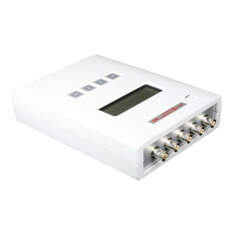
Audio Precision AUX-0025 User manual

Switching Amplifier Measurement Filter
AUX-0025
USER’S MANUAL


AUX-0025
User’s Manual
Installation and Operation of the
AUX-0025
Switching Amplifier Measurement Filter

No part of this manual may be reproduced or transmitted in any
form or by any means, electronic or mechanical, including
photocopying, recording, or by any information storage and
retrieval system, without permission in writing from the
publisher.
Audio Precision®, System One®, System Two™, System Two
Cascade™, System One + DSP™, System Two + DSP™, Dual
Domain®, FASTTEST®, APWIN™, ATS™ and ATS-2™ are
trademarks of Audio Precision, Inc. Windows is a trademark of
Microsoft Corporation.
Published by:
5750 SW Arctic Drive
Beaverton, Oregon 97005
Tel: 503-627-0832
Fax: 503-641-8906
US Toll Free: 1-800-231-7350
email: [email protected]
Web: audioprecision.com
Printed in the United States of America
Copyright Ó2003 Audio Precision, Inc.
All rights reserved.
Audio Precision part number 8211.0180 Rev 1
VI0424102522

Contents
Safety ..................................iii
Chapter 1
Introduction ..............................1
A Switching Amplifier by any name... ................2
Features of the AUX-0025 .......................3
Passive design ............................3
Inductors ...............................3
Connectors ..............................3
Cables .................................3
Mounting ...............................3
Chapter 2
Using Your AUX-0025 ........................5
Connections ..............................5
Connecting the DUT to the AUX-0025 ...............5
Connecting the DUT to a Load ...................6
Connecting the AUX-0025 to the Analyzer ............6
Typical waveforms ...........................6
Use of additional filters ........................7
Use with SWR-2122 switchers .....................8
Sample Tests ..............................8
Chapter 3
Specifications .............................9
AUX-0025 User’s Manual i

ii AUX-0025 User’s Manual

Safety
The two AUX-0025 front-panel terminals marked with this sign are a
chassis common connection. They are NOT a safety ground, and are not
intended for use as a safety ground connection.
AUX-0025 User’s Manual iii

iv AUX-0025 User’s Manual

Chapter 1
Introduction
Audio analyzers are generally designed to have broad measurement
bandwidths, broader than a typical audio circuit or system and much
wider than the audio passband. Such designs enable accurate analysis of
fast, high-performance audio circuits and also allow measurement of any
low-level high-frequency spurious signals that may accompany the audio
signal.
This design philosophy is based on the assumption that the audio signal
and its overtones are the dominant signal components applied to the ana-
lyzer; this is the case for the output of conventional audio power amplifiers
of Class A or Class AB design. In such a case the analyzer can range its cir-
cuits to the amplitude of the audio signal for optimum measurement
conditions.
Recent practice, however, has often turned to other amplifier designs for
improvements in efficiency and weight as compared to Class A and Class
AB amplifiers. Although these amplifier designs vary, as do the names ap-
plied to them, they have in common an output signal that is a high-fre-
quency switching carrier modulated by the audio signal. Many of these
“switching amplifiers” or “digital amplifiers” present a difficulty to conven-
tional measurement and analysis techniques due to the out-of-band switch-
ing carrier components that are in the output signal. When the amplitude
of the switching carrier components remains high in comparison to the
AUX-0025 User’s Manual 1
Figure 1. The Audio Precision AUX-0025 Switching Amplifier Measurement Filter.

audio signal, the ranging functions of an audio analyzer may respond to
the carrier rather than to the audio signal, reducing the accuracy of the
measurements.
The best solution in using a broad range, broad bandwidth analyzer to
accurately measure the output of such an amplifier is to insert a care-
fully-designed low-pass filter between the output of the device under test
(DUT) and the analyzer input to reduce amplitude of the switching carrier
before the signal is ranged. The Audio Precision AUX-0025 Switching Am-
plifier Measurement Filter fulfills this requirement.
A Switching Amplifier by any name...
In this document we will refer to audio amplifiers with modulated switch-
ing carrier outputs as switching amplifiers; in other literature the term
switchmode amplifier may be used. These devices include Class D, Class I
and Class S amplifiers and also Class T amplifiers and “digital amplifiers.”
Generally, switching amplifiers impose the audio signal on the carrier by
pulse width modulation (PWM). (Class T is a variation on this, adding a dy-
namic modulation of the carrier frequency and other signal processing).
Switching amplifiers designed for a limited bandwidth (such as
subwoofer amplifiers) may use a carrier frequency as low as 80 kHz.
Full-range amplifiers have higher carriers, up to 1.5 MHz or more.
Some switching amplifiers provide no filtering at their output and de-
pend upon the inductance and mass of the loudspeaker to integrate the sig-
nal, reproducing the audio but not the inaudible carrier. Other amplifiers
include an output low-pass filter, which reduces EMI and aids the loud-
speaker in integrating the signal, but which is generally not sufficient for ac-
curate measurement by an external analyzer.
Chapter 1: Introduction A Switching Amplifier by any name...
2AUX-0025 User’s Manual
Figure 2. A diagram of a sine wave and a pulse width modulated (PWM) switching carrier
modulated by the same wave.

Features of the AUX-0025
The AUX-0025 is a dual-channel passive low-pass filter specifically de-
signed to minimize switching amplifier carrier components while passing a
broad audio spectrum. This filter provides the signal preconditioning neces-
sary to accurately measure switching amplifier outputs using a wide-range
audio analyzer.
Passive design
For this application, a passive filter was determined to be the best ap-
proach. An active filter would require input attenuation and variable gain
to accommodate the wide range of signal amplitudes that might be ap-
plied, adding noise and distortion to the signal.
Inductors
Custom inductors were specified with an emphasis on power handling
and minimizing low-frequency distortion while satisfying the filter response
requirements.
Connectors
The AUX-0025 input connectors duplicate the balanced female
XLR-type and dual-banana jacks found on Audio Precision System 2000
Series instruments. A common connection is conveniently provided next to
each channel input. The common terminal will accept a banana plug or a
bare wire connection.
The filtered outputs of the AUX-0025 are provided on balanced male
XLR-type connectors.
Cables
For proper performance, the analyzer input impedance that the
AUX-0025 looks into must be high, with a maximum total capacitive load-
ing (including interconnecting cables) of 360 pF. Two short, low-capaci-
tance XLR-to-XLR cables are provided for the connection between the
AUX-0025 and the analyzing instrument to help ensure a proper loading.
Mounting
The AUX-0025 is fitted with resilient feet for tabletop use. It can also be
rack-mounted using the optional rack mount adapters available from Au-
dio Precision. Being a passive unit, the AUX-0025 does not dissipate ap-
preciable power and requires no extraordinary ventilation considerations.
Features of the AUX-0025 Chapter 1: Introduction
AUX-0025 User’s Manual 3

The AUX-0025 should not be mounted close to a source of strong mag-
netic fields such as a power transformer. Stray magnetic fields could cause
degradation in system residual hum and noise performance.
Audio Precision products such as the System 2000 Series
and ATS-2 instruments are designed to minimize and contain
stray magnetic and electrostatic fields that may be produced
within the instrument. The AUX-0025 may be placed directly
on top of Audio Precision instruments with no degradation in
system performance.
Chapter 1: Introduction Features of the AUX-0025
4AUX-0025 User’s Manual

Chapter 2
Using Your AUX-0025
Connections
Connecting the DUT to the AUX-0025
For a DUT with balanced outputs
§connect the high side of the amplifier output to the top banana
connector (marked +) or to pin 2 of the female XLR-type connector,
and
AUX-0025 User’s Manual 5
AUX-0025
Switching Amplifier
Measurement Filter
ANALOG INPUT
ANALOG INPUT
ANALOG OUTPUT ANALOG OUTPUT
CHANNEL B
CHANNEL A
Pin1: COMMON (SHIELD)
Pin2: BAL+ or UNBAL HI
Pin3: BAL- or UNBAL LO
Pin1: COMMON (SHIELD)
Pin2: BAL+ or UNBAL HI
Pin3: BAL- or UNBAL LO Loadnot to exceed 360 pF
Loadnot to exceed 360 pF
200VpkMAX
!
200VpkMAX
!
R
Audio Precision
S
y
stem 2000 Instrument Switching Amplifier
Under Test
Power
Load
Resistors
AUX-
002
5 Filter
Figure 3. Diagram of a switching amplifier output properly connected to the AUX-0025
(and analyzer) and to an amplifier load.

§connect the low side of the amplifier output to the bottom banana
connector (marked –) or to pin 3 of the female XLR-type connector.
For a DUT with unbalanced outputs
§connect the amplifier output to the top banana connector
(marked +) or to pin 2 of the female XLR-type connector, and
§connect the amplifier common or ground to the bottom banana
connector (marked –) or to pin 3 of the female XLR-type connector.
Common connections should be made to the common terminal for
each channel, marked with this symbol.
Connecting the DUT to a Load
Although useful measurements can be performed on switching amplifier
outputs when unloaded, it is usually desirable to measure the amplifier per-
formance while working into a load, whether a resistive “dummy load” or
an actual loudspeaker.
When using the AUX-0025 in a test with a load, be sure that the mea-
surement connections are made at the point physically and electrically clos-
est to the amplifier output circuitry, rather than at the load. The very slight
reduction in connection and wire impedance obtained using this practice
will provide more accurate and consistent amplifier output measurements.
Connecting the AUX-0025 to the Analyzer
For proper performance, the analyzer input impedance that the
AUX-0025 looks into must be high. (The DUT output impedance must be
low [<2 W] as well, but this is consistent with switching amplifier designs.)
For Audio Precision analyzer instruments, use the HiZ setting. Never ter-
minate the AUX-0025 outputs with an impedance less than 100 kWresis-
tive or greater than 360 pF capacitive.
The high side of the AUX-0025 output is on pin two of each of the
XLR-type output connectors. The low side is carried on pin three while pin
one is the shield termination, connected to the AUX-0025 chassis com-
mon. The AUX-0025 can be connected to either a balanced or unbal-
anced analyzer input, as long as the input, cables and adapters used do
not present a load impedance less than 100 kWresistive or greater than
360 pF capacitive.
Two short, low-capacitance XLR-to-XLR cables are provided for the in-
terconnection between the AUX-0025 and the analyzing instrument to
help maintain a high load impedance and recommended load
capacitance.
Chapter 2: Using Your AUX-0025 Connections
6AUX-0025 User’s Manual

Typical waveforms
The two oscilloscope traces shown in Figures 4 and 5 show time-do-
main views of the unfiltered and filtered output for a particular amplifier.
Different amplifiers and load configurations can produce oscilloscope wave-
forms that are quite different than these.
Figure 4. An oscilloscope capture of a switching amplifier output signal. The
high-frequency, high-level switching carrier is shown riding the lower-frequency audio
Figure 5. An second oscilloscope capture of the sane switching amplifier output as shown
in Figure 4, after the application the AUX-0025 filter. The switching carrier has been
greatly reduced.
Typical waveforms Chapter 2: Using Your AUX-0025
AUX-0025 User’s Manual 7

Use of additional filters
The AUX-0025 filter reduces the switching carrier and other out-of-band
components to a sufficient degree for accurate measurement, but it is not
designed to remove all out-of-band noise.
In many cases you may want to apply additional low-pass filtering
within the analyzer. Both the Audio Precision ATS-2 and the System 2000
instruments have additional filtering available.
A standardized and very effective technique to reduce out-of-band com-
ponents for measurement is the use of the Audio Precision S-AES17 filter
set, available for System 2000 Series instruments.
Use with SWR-2122 switchers
The characteristics of the Audio Precision SWR-2122 series switchers
are completely compatible with the AUX-0025. The appropriate balanced
or unbalanced switcher can be used to automatically switch the filter / in-
strument inputs among several DUTs.
Sample Tests
The CD-ROM provided with your AUX-0025 has a selection of sample
Audio Precision tests for use with switching amplifiers. Open the file
Readme.doc for a description of the sample test files.
For more information about your AUX-0025 Switching Amplifier Mea-
surement Filter and switching amplifiers in general, visit the Audio Preci-
sion Web site at audioprecision.com.
Chapter 2: Using Your AUX-0025 Use of additional filters
8AUX-0025 User’s Manual

Chapter 3
Specifications
Specifications
Frequency Response ±0.05 dB, 10 Hz to 20 kHz
Insertion Loss 0.05 dB, typically
High-frequency Rejection >50 dB, 250 kHz to 20 MHz, typically
Maximum Input ±200 V peak
Interchannel Crosstalk >90 dB at 20 kHz
Distortion < –110 dB harmonic (measured at 70 Vpp, 1 kHz)
< –100 dB IMD (measured at 70 Vpp with 18 kHz
and 20 kHz dual tone test signal. IMD
components are at 2 kHz, 16 kHz and 22 kHz.)
Dimensions
Temperature Range
Operating +5º C to +40º C
Storage –40º C to +75º C
Humidity 80% RH to at least +90º C
Dimensions 16.5 x 1.75 x 10.5 inches
(41.9 x 4.4 x 26.7 centimeters)
Weight 7.2 lb (3.3 kg) unpacked
AUX-0025 User’s Manual 9

Filter Response Graphs
Chapter 3: Specifications
10 AUX-0025 User’s Manual
20 500k50 100 200 500 1k 2k 5k 10k 20k 50k 100k 200k
Hz
-60
+5
-55
-50
-45
-40
-35
-30
-25
-20
-15
-10
-5
+0
d
B
r
A
Figure 6. AUX-0025 overall response showing attenuation beyond the audio band.
-0.1
+0.1
-0.075
-0.05
-0.025
-0
+0.025
+0.05
+0.075
d
B
r
A
10 50k20 50 100 200 500 1k 2k 5k 10k 20k
Hz
Figure 7. AUX-0025 passband response showing flatness out to 20 kHz.
Table of contents
Other Audio Precision Measuring Instrument manuals
Audio Precision
Audio Precision Lynx Aurora User manual
Audio Precision
Audio Precision B Series User manual

Audio Precision
Audio Precision B Series User manual
Audio Precision
Audio Precision AP 52 B Series User manual
Audio Precision
Audio Precision APx52 series User manual
Audio Precision
Audio Precision APx555 User manual

Audio Precision
Audio Precision B Series User manual
Audio Precision
Audio Precision APx500 Flex User manual
Audio Precision
Audio Precision ATS-1 User manual

Audio Precision
Audio Precision B Series User manual


