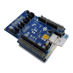
BEST Robotics IR Sensor System User manual

Test and Adjustment of IR Sensor System
Educational Revision BEST Robotics Inc © 2019 Page 1
Test & Adjustment of the IR Sensor System
Goal: To conduct simple tests for correct operation of the assembled BEST IR Sensor Kit
and to make adjustments for sensitivity.
Materials Needed
•BEST IR Sensor System (Assembled PCBs)
•5V Power Supply
•Mini test hook probes (recommended)
•3-wire cables (2)
•Solderless breadboard (optional)
•Oscilloscope or frequency counter (optional)
This document will walk you through testing the BEST IR Sensor System’s operation and adjusting its
sensitivity.
Step 1: Separate the PC Boards
In the kit the two PC boards are manufactured as a single board to make it a little larger for
easier assembly. After soldering on all the components, the two boards will be cut apart. If you have
not already done so, cut the board as described in the final step of the assembly instructions.
Receiver
Transmitter
Carefully Cut Boards Apart Here

Test and Adjustment of IR Sensor System
Educational Revision BEST Robotics Inc © 2019 Page 2
The board that emits the IR light is the transmitter and is the larger of the two boards. The IR
emitting diode is the clear one, located on one edge of the board. Note that as supplied it emits light in
a direction perpendicular to the plane of the board. If you want it to emit light in the plane of the board,
carefully bend the two leads 90 degrees, the IR diode will extend beyond the edge of the board.
The board that receives the IR light is the receiver and is the smaller of the two boards. The IR
detecting IC is the dark, 3-legged device with a bump on its side, located on one edge of the board. The
bump is a lens so the IR should shine on the bump. Note that as supplied it is “looking” in the plane of
the board. If you want it to “look” in a direction perpendicular to the plane of the board carefully bend
the IC back so the bump is away from the board. There is a clear area on the board that it should fit into
without hitting anything.
Note that the leads on the IR emitting diode and IR detecting IC can likely only be bent one time
without breaking the leads so you should think carefully before making your decisions on orientation.
The two large holes, one on each board, are for mounting and are sized for a #4 screw.
IR Emitting Diode
IR Detecting IC

Test and Adjustment of IR Sensor System
Educational Revision BEST Robotics Inc © 2019 Page 3
Step 2: Setup and Test Beam Breaking Operation
This is the simplest testing option, needing only a +5V power supply. The IR emitter runs
continuously. It is suitable for a “beam break” application.
Note: Be sure to get the polarity of the power supply correct.
Using a 3-wire cable, connect the power supply to the receiver board. The male end of the cable
connects to the power supply. Using a solderless breadboard makes this a lot easier than trying to clip
on to those tiny connector pins without shorting anything. The female end of this cable plugs onto 3 of
the 4 pins on the receiver board (J2) with the black wire connected to the pin closest to U2 (the dark 3-
pin IR detector IC). The 4th pin on the receiver board, the pin closest to the edge of the board, remains
unconnected.
Using another 3-wire cable, connect the receiver board to the transmitter board. The male end
of the cable plugs into the 3-pin socket on the receiver board (J3), with black wire connected to the
same end as that of the first cable on J2. Note that the cable’s connector will be offset 0.1” from the
first cable’s connector. The female end of this cable plugs onto the 3-pin connector on the XMT board
(J1), with the black wire connected to the pin closest to the bright yellow capacitor (C2), away from the
corner of the board.
When you apply power the red LED on the XMT board should turn on. You can monitor the
operation using the red LED on the RCV board. When the RCV board detects the signal from the XMT
board, the red LED on the RCV board will turn on. When you block the IR signal or turn the XMT board
in a different direction, the red LED on the RCV board will go out. Note that as drawn in figure 1 the
transmitter emits light up, out of the page, and the receiver is “looking” toward the bottom of the page.
Please see assembly instructions for more details.

Test and Adjustment of IR Sensor System
Educational Revision BEST Robotics Inc © 2019 Page 4
Step 3: Adjust the System’s Sensitivity
For help in debugging, the transmitter board has a red LED that will be on when the IR emitter is
on. The receiver board has a red LED that will be on when an IR signal is detected. Due to the limited
power available, the receiver LED is fairly dim.
The IR signal is modulated at 38KHz to reduce sensitivity to other light sources – the detector is
tuned to 38KHz and is less sensitive to constant light or other modulation frequencies. For maximum
sensitivity tune the transmitter board to 38KHz. You can adjust the modulation frequency to adjust the
system’s sensitivity by turning the white potentiometer on the transmitter board. There are a couple
ways to make this adjustment.
If you have an oscilloscope or frequency counter connect it to pin 7 of the 8-pin DIP to monitor
the frequency. If you lack that equipment, don’t panic. You can do a pretty good job without any
special test equipment. Separate the transmitter and receiver until the receiver just barely detects the
IR signal. Now when you adjust the potentiometer you should find that the receiver detects the IR
signal somewhere in the middle of its range of travel but does not detect the IR signal at either the
counter-clockwise extreme or the clockwise extreme. Find the two spots of the potentiometer’s travel
where it switches between detecting and not detecting and set the potentiometer halfway between
these two points.
You may not want maximum sensitivity. Perhaps your transmitter and receiver are very close
together, counting wheel spokes as they go past, for example. Frustratingly, it doesn’t work reliably
because the receiver is also picking up reflections from other parts of your robot. In this case you can
“detune” the transmitter so that your receiver can detect the strong signal from the transmitter but not
the weaker reflections. Flat black paint may also be your friend here.
Table of contents
