Heatrae Sadia HRU ECO 4 User manual
HRU ECO 4
User manual

Translation of the original document.

Introduction
This manual is intended for the user of the device and
contains important information about safe and correct
use, maintenance and troubleshooting of the appliance.
The installer is responsible for installing and
commissioning the unit.
The following definitions are used in this manual to draw
attention to hazards, instructions or indications related to
people, products, installations and/or the surroundings.
ä Warning!
Indicates a hazard that can cause injury and/or severe
damage to the product, system or surrounding area.
ä Caution!
Instructions important for the installation, functioning,
operation or maintenance of the product. Failure to
observe these instructions can result in minor injury
and/or severe damage to the product, system or
surrounding area.
Note
Instructions important for the installation, functioning,
operation or maintenance of the product. Failure to
observe these instructions can result in minor damage
to the product, system or surrounding area.
Tip
Instructions that may be important for the installation,
functioning, operation or maintenance of the
product, but are not related to injury or material
damage.
Tip
Do not forget to register the product via the Heatrae
Sadia website www.heatraesadia.com.
Although this manual has been drawn up with the utmost
care, no rights may be derived from this document.
Heatrae Sadia reserves the right to modify products and
manuals without prior notice.
Due to our continuous product improvement process,
this document may not match the appliance you
received. You can download the latest version of the
manual from www.heatraesadia.com.
Tip
Please keep the manual in its designated storage slot
on the ventilation unit.
3

Contents
1. Safety and other regulations 5
1.1. Safety 5
2. Product information 7
2.1. A comfortable living environment
and energy conservation
7
2.2. Heat recovery 8
2.3. Filters 8
2.4. Controls 8
2.5. Grilles 10
2.6. Applications with new housing
developments
10
2.7. Product fiche information 12
2.8. Accessories 13
2.9. Recycling 13
3. Operation 14
3.1. Ventilation speeds 14
3.2. Devices 15
3.3. Sensors 15
3.4. Pairing and unpairing wireless
devices and sensors
15
4. Inspection and maintenance 17
4.1. Inspection and maintenance
schedule
17
4.2. Inspecting, cleaning and replacing
filters
18
4.3. Cleaning the insect filter 19
4.4. Inspecting and cleaning air valves 20
4.5. Wireless device maintenance 20
5. Faults 21
6. Warranty 26
7. Declarations 27
4

1. Safety and other
regulations
1.1. Safety
●Work may only be performed
on the ventilation system by
qualified installers in
accordance with the
regulations mentioned in this
manual. Only original
accessories and parts as
specified by the manufacturer
may be used for this purpose.
●Do not use the product for
purposes other than those for
which it is intended, as
described in this manual.
●Be careful when using
electrical appliances:
-Never touch the appliance
with wet hands.
-Never touch the appliance
when barefoot.
●This product and/or system
may be operated safely by
children aged 8 years and
older and by people with
physical, sensory or mental
disabilities or a lack of
experience/knowledge if
under supervision or after
having received instructions
regarding safe use, and if they
are aware of the product
and/or system hazards.
●Cleaning and maintenance by
the user may not be done by
children or people with
physical, sensory or mental
disabilities or a lack of
experience/knowledge
without supervision.
●Do not allow children to play
with the product and/or
system.
●Do not use the product in the
vicinity of flammable or volatile
substances such as alcohol,
insecticides, petrol etc.
●The safety instructions must be
followed in order to prevent
physical injury and/or damage
to the product.
●The product includes moving
parts. Please therefore wait at
least 10 seconds after
disconnection prior to
opening or touching the
product as these parts will
continue to move for some
time.
●Secure the appliance against
being switched on
accidentally.
5

●Maintenance instructions must
be followed to prevent
damage and excessive wear
and tear.
●The product may not be
modified.
●The product is only suitable for
use with a 230 V, 50 Hz AC
power supply system.
●Ensure that the electrical
system to which the product is
connected meets the
necessary conditions.
●Do not expose the product to
the elements.
●Do not place any objects on
top of the device.
●Inspect the product regularly
for faults. In the event of faults,
switch the product off and
contact your installer or
Heatrae Sadia Customer
Service immediately.
●Switch the product off if:
-The product is not working
properly.
-You want to clean the
outside of the product.
●Ensure that the electrical
circuit does not become
damaged.
●Do not use the device to
extract air from boilers,
heating systems etc.
●Ensure that the device drains
into a sewer system which
leads outside, and is suitable
and installed for this purpose.
●Ensure that air valves and
grilles are not obstructed, and
that they are clean.
6
2. Product information
2.1. A comfortable living environment
and energy conservation
A comfortable living environment and energy
conservation are becoming increasingly important in
housing construction. The insulation of modern dwellings
is getting better all the time, but unfortunately good
insulation often comes at the expense of the indoor
climate. Without good ventilation, there is nothing to
stop damp, mould and dust mites, and the air in the
dwelling can quickly start to feel stale due to the
increasing CO2 concentration (carbon dioxide). Heatrae
Sadia installs appliances which manage the indoor
climate and take account of requirements for comfort and
energy consumption in dwellings.
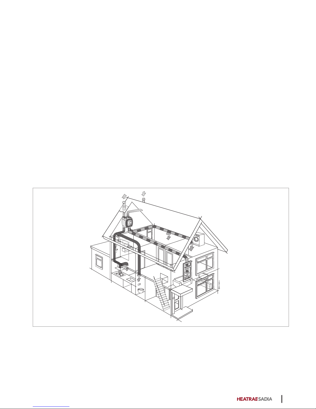
The HRU ECO 4 ventilation system from Heatrae Sadia is
an example of these advanced appliances.
The HRU ECO 4 is a balanced ventilation system with
heat recovery. The ventilation unit is equipped with two
fans: one for air exhaust and one for air supply.
The unit ventilates several rooms in the dwelling. Stale or
humid air is extracted from the kitchen, bathroom, toilet,
and any indoor storage spaces or washrooms ("wet
rooms") through ducts connected to the ventilation unit.
The living room, bedrooms and hallway are also
connected to the ventilation unit by ductwork, but in
these rooms there is no air extraction, just fresh air
supply.
To ensure good air distribution, the extraction and supply
points in the ventilated rooms are fitted with extractor
valves and supply grilles.
The HRU ECO 4 helps to reduce humidity in your
bathroom, keep the toilet smelling fresh and remove
cooking odours from the kitchen.
2
7

2.2. Heat recovery
Before the stale air is discharged outside, it is filtered and
passes through the heat exchanger. The fresh outside air
is also filtered and passes through the heat exchanger
before entering the dwelling. In the heat exchanger, the
two air streams pass alongside each other but are not
mixed together. This allows heat from the exhaust air to
be transferred to the fresh supply air, so this energy is not
lost.
This heat recovery process is very efficient. On average,
around 90% of the extracted heat is returned to the
dwelling. This means that only around 10% of the heat is
lost.
Note
Despite the heat exchange process whereby Supply
air from outside is pre-heated, the balanced
ventilation system may not be regarded as a heating
system. It is a ventilation system that contributes to a
comfortable and healthy living environment in a
dwelling.
2.3. Filters
The HRU ECO 4 has two filters, one for each air stream.
Both filters are positioned in the ventilation unit so that
they protect the exchanger against soiling. In addition,
the filter in the air supply channel protects the user
against dust and other impurities found in the air drawn
in from outside.
There are various types of filters:
●G3 filter.
This filter is supplied with the appliance as standard
and it is very suitable as a 'construction dust filter' in
the initial period following completion of the new
housing. After around three months, the filter should
be replaced with a G4 or F7 filter.
●G4 filter.
This coarse filter is mainly used to filter relatively
large dust particles from the air. This protects the
heat exchanger in particular against incoming dirt.
●F7 filter.
This fine filter stops fine dust particles as well as
coarser dust particles (fine dust, pollen). This is
particularly beneficial for people with allergies who
are sensitive to this.
During the product's lifetime the filters will become dirty,
which reduces the capacity of the ventilation unit. It is
therefore essential that the filters are cleaned as
indicated and ultimately replaced.
ä Warning!
HRU ECO 4 should always be fitted with the
appropriate filters. Without filters, the appliance can
be irreparably damaged.
2.4. Controls
The HRU ECO 4 is normally equipped with a three-level
control which allows the flow rates at low speed and high
speed to be adjusted as desired with potentiometers on
the unit. In addition, the ventilation unit has some
automatic controls that operate continuously in the
background.
2.4.1. Summer bypass control
The aim of the summer bypass control is the ventilation
of the dwelling with less heat transfer or none
whatsoever.
The Heatrae Sadia HRU ECO 4 heat recovery unit is
supplied as standard with a bypass valve which is fully
integrated into the unit. This valve operates fully
automatically. The bypass allows the outdoor air intake to
go around the heat exchanger. The exhaust air always
passes through the heat exchanger.
This automatic control will primarily be activated at night
in the summer. The outside air is usually cooler than the
warm inside air at this time.
Note
The summer bypass control is not a cooling device,
but it does ensure that the dwelling remains cool for
longer on summer nights.
2.4.2. Frost protection
The HRU ECO 4 is equipped with frost protection as
standard. The frost protection consists of a unique frost
valve integrated into the top of the unit, as well as other
components. This valve operates fully automatically and
prevents freezing inside the ventilation unit during winter
weather.
The air extracted from the dwelling (exhaust air) transfers
heat to the outside air sucked in by the unit. This cools
the exhaust air in the heat exchanger. If the temperature
of the exhaust air in the heat exchanger comes too close
to the freezing point, the appliance will open the frost
8

valve at the top of the unit and suck in warm room air.
This warm room air is mixed with the sucked-in cold
outside air.
At the same time, the supply fan starts running faster so
that the amount of fresh outside air remains the same.
Thanks to this preheating of the cold outside air, the
warm air extracted from the dwelling does not have to
warm up the cold fresh air as much. As a result, the
temperature of the exhaust air in the heat exchanger
remains safely above the freezing point.
If the outside temperature drops even further, the supply
fan will slow down until it ultimately reaches a minimum
speed.
If the temperature drops even further, the exhaust fan
speed will be increased and the supply fan will continue
to run at minimum speed. If the outside temperature
becomes extremely low, the supply fan will be switched
off but the exhaust fan will continue running. The frost
valve is also closed in this case.
After a defined time, the supply fan will start running
again at minimum speed and the frost valve will be
opened again to check whether the frost risk has gone
away. If the outside temperature rises, the above actions
occur in the reverse order until the frost risk is gone. The
resident always determines the exhaust air volume.
2.4.3. Automatic ventilation based on
CO2 measurement
A wireless CO2 sensor can be connected to the
ventilation unit.
To ensure a healthy indoor climate and to prevent the air
in the dwelling from becoming stale, it is important that
the the CO2-level is not too high.
The sensor can be placed in any room (except the
bathroom), but should preferably be placed in the living
room or bedroom.
The CO2-sensor measures the CO2-level in the room. It
translates the measured value into a ventilation demand
and communicates this via wireless to the ventilation unit
with which it is paired. This allows ventilation to be
continuously and automatically adjusted, and it ensures
that a good indoor climate is achieved in the most
effective and energy efficient manner.
When the the CO2-level has fallen sufficiently, the
capacity of the ventilation unit is automatically decreased.
Tip
It is possible to place several wireless sensors and
controls in the dwelling, up to a maximum of 20.
2.4.4. Automatic ventilation based on
RH measurement
A wireless RH sensor can be connected to the ventilation
unit.
To ensure a healthy indoor climate and to prevent
patches of damp and mould in the dwelling, it is
important that the relative humidity does not stay high for
too long.
The sensor can be placed in any room as desired, but
preferably in a room where a lot of moisture is produced,
such as a bathroom.
The RV-sensor measures the relative humidity in the
room. The sensor translates the measured value into a
ventilation demand and communicates this via wireless to
the ventilation unit paired with the sensor. This allows
ventilation to be continuously and automatically adjusted,
and ensures that a good indoor climate is achieved in the
most effective, energy-efficient manner.
When the relative humidity has fallen sufficiently, the
capacity is automatically decreased.
2.4.5. Automatic ventilation based on
occupancy
A wireless PIR sensor can be connected to the ventilation
unit.
To ensure a healthy indoor climate and to prevent
unpleasant odours in the dwelling, it is important that
there is enough ventilation when people are present.
The sensor can be placed in any room, for example in the
toilet or in a bathroom with a toilet.
The sensor detects the presence (or absence) of people
in the room and communicates this wirelessly to the
ventilation unit with which it is paired.
If the ventilation unit is in Auto mode, the capacity is
continuously and automatically adjusted.
If the sensor detects movement, the ventilation system
runs at increased capacity for a defined period. If the
sensor detects continuous occupancy of the room, the
capacity will be increased even more. If the motion
sensor does not detect any movement within a set
period, the capacity will automatically be decreased
again.
ä Caution!
Control based on wireless sensors (CO2, RV and/or
PIR) only works when the ventilation unit is in Auto or
Auto-Night mode.
9
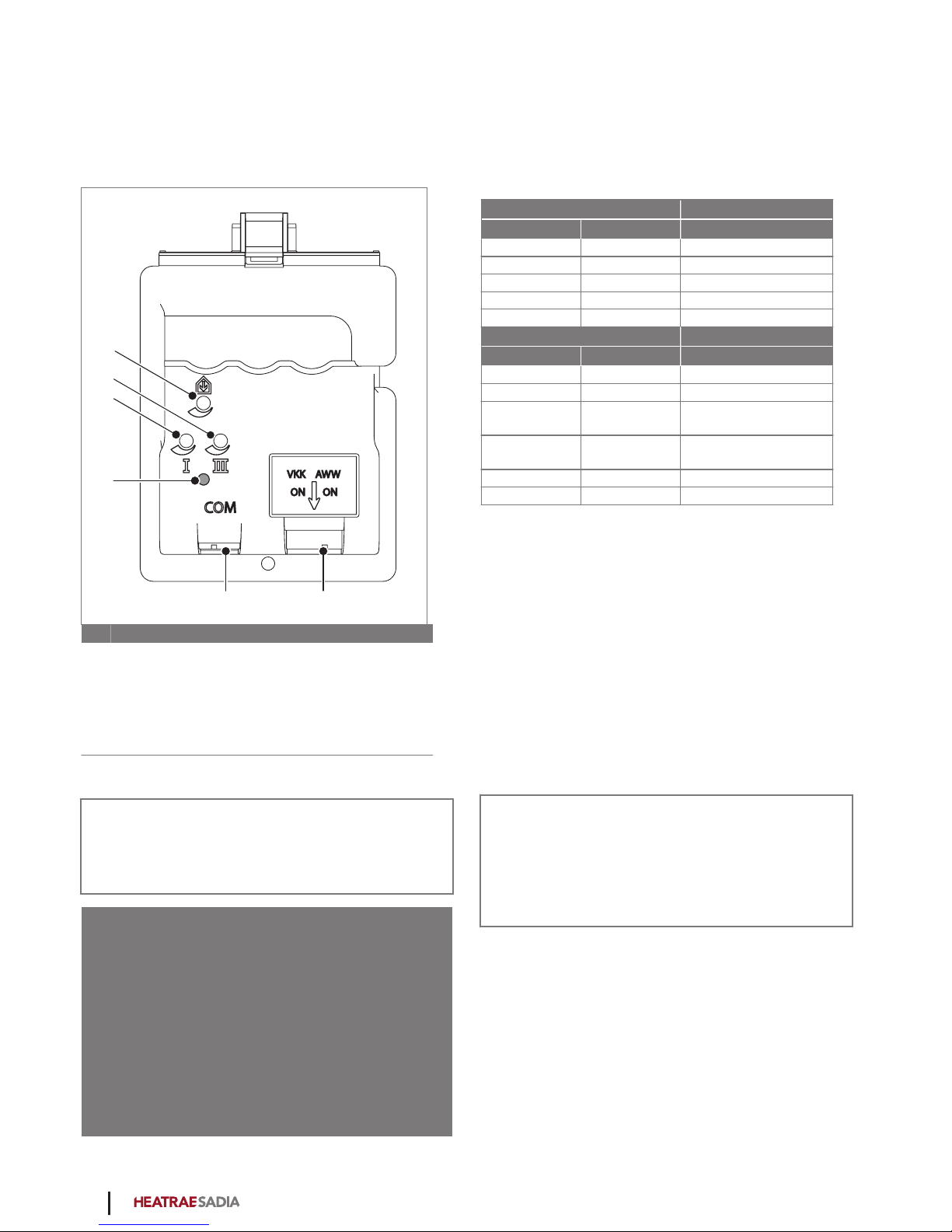
2.4.6. Filter warning
The controller of the ventilation unit uses a counter to
keep track of when the filters need to be cleaned or
replaced. If it detects that a filter is dirty, an LED (4) on
the ventilation unit starts blinking orange.
1
2
3
4
5 6
AWW
ON ON
VKK
COM
Key
1Balance supply setting
2Potentiometer for high speed setting
3Potentiometer for low speed setting
4Status LED / Dirty filter indication
5Communication port
6DIP switch settings (VKK & AWW)
Note
It is advisable to check the LED on the ventilation unit
on a regular basis.
ä Caution!
If a dirty filter is detected, a signal is also sent to the
resident by suddenly reversing the operation of the
control: when the Low Speed button on the remote
device is pressed, the ventilation unit starts running at
high speed, and when the High Speed button is
pressed the ventilation unit starts running at low
speed. When this happens, check the LED on the
ventilation unit. If it is blinking orange, the filter needs
to be cleaned or replaced.
2.4.7. Status LED
The appliance is equipped with a status LED on the
control panel. The status LED can display the following
messages:
Pattern Function
Green Orange
Blinks 1x/s Blinks 1x/s Identification
Blinks 1x/s Pairing mode
Lit 6 s Blinks 1x/s Frost mode
Lit 5 s Blinks 2x/s Bypass mode
Lit Normal operation
Pattern Function
Red Orange
Blinks 1x/s Blinks 1x/s Exhaust fan fault
Blinks 1x/s Blinks 2x/s Supply fan fault
Blinks 2x/s Blinks 2x/s Exhaust temperature
sensor fault
Blinks 2x/s Blinks 3x/s Supply temperature
sensor fault
Blinks 3x/s Blinks 1x/s Sensor fault
Blinks 1x/s Filter dirty
2.5. Grilles
The quantity of air that must be extracted is legally
regulated, and the quantity of air supplied must stand in
proportion to this. This means that the same amount of
air must be supplied as is extracted. The minimum air
quantity per room is also legally regulated. The quantities
have been selected to ensure that no unnecessary energy
is wasted whilst still achieving an optimal indoor climate.
This is why the air extraction and supply valves differ in
size between rooms. Each of the extraction and supply
grilles therefore has a specific fixed position and setting.
Note
It is very important that you do not adjust the grilles
in any way, to ensure proper operation of the entire
ventilation system. Grilles and air valves should not
be swapped around.
2.6. Applications with new housing
developments
High levels of moisture is found in building materials for
new housing – about 4,000 litres per house on average.
This moisture originates from wet building materials such
as concrete, cement, plaster and adhesives. Materials can
also become wet from rain during the construction
period. The best way to eliminate this moisture is to
10

ventilate the house properly and keep the temperature as
constant as possible.
Forced drying: not too fast
Heating the house to promote the drying process is
sometimes called forced drying. Forced drying should
not be done too quickly, otherwise significant damage
(such as contraction cracks) can occur. It is therefore
recommended to give careful attention to forced drying.
Bear in mind that the forced drying process may take as
long as six months. Set the heating to 15 to 18°C, and
raise it to 20°C after moving in. Do not set the heating
any higher, as the materials will start drying too quickly
and damage to the building structure may occur.
Ventilation during forced drying
Good ventilation and air circulation are essential during
the drying process. During the first year, keep furniture
approximately 5 cm away from the walls to allow the
moisture to escape. Open the windows each day for
sustained periods. The ventilation grilles must remain
open all the times and the forced air ventilation system
should be left to run constantly (don't unplug it), Run the
forced air ventilation system at high speed as often as
possible during the first few months.
This will create the most favourable air circulation in the
house.
Energy costs
Good, continuous ventilation is not only important for
good health; it is also important to avoid moisture
problems in the house. However, ventilation takes heat
out of the house. Forced drying new houses also results
in higher energy consumption, resulting in a higher
energy costs.
11
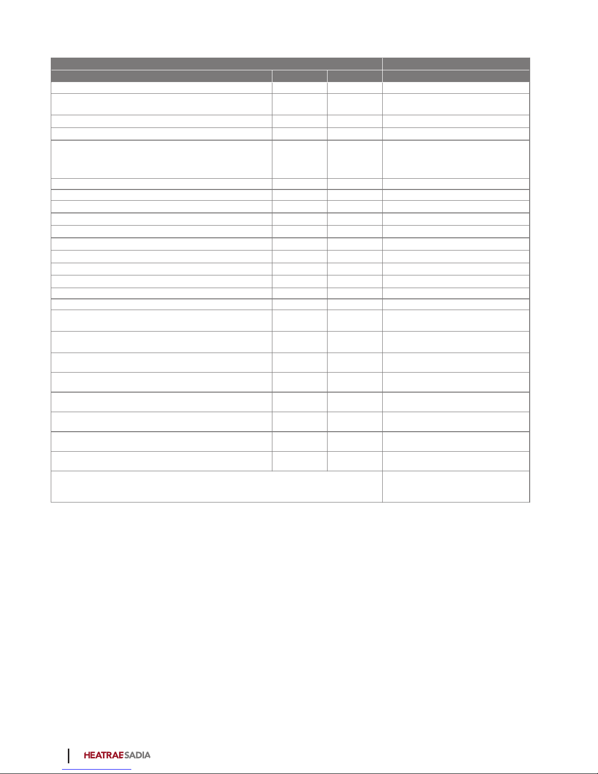
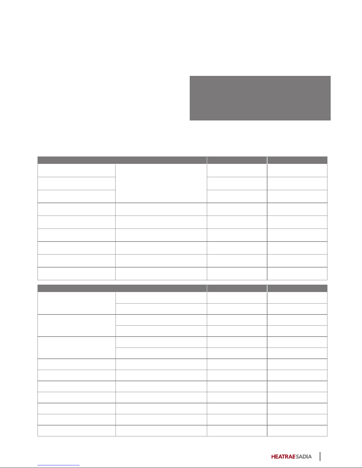
2.7. Product fiche information
Heatrae Sadia HRU ECO 4
Description Symbol Unit
Specific energy consumption class — — A
Specific energy consumption under average climate
conditions SEC kWh/(m2.a) -37
Specific energy consumption under warm climate conditions SEC kWh/(m2.a) -12
Specific energy consumption under cold climate conditions SEC kWh/(m2.a) -78
Type of ventilation unit VU —
- Residential ventilation unit (RVU)
- Bidirectional ventilation unit
(BVU)
Type of drive — — Variable speed
Type of heat recovery system HRS — Recuperative
Thermal efficiency of heat recovery ƞt% 88
Maximum flow rate qmax m3/h 350
Electric power input of fan drive at maximum flow rate Pmax W 154
Sound power level LWA dB 52
Reference flow rate qref m3/s 0.069
Reference pressure difference ΔPref Pa 50
Specific power input SPI W/(m3/h) 0.255
Ventilation control — — Manual control (no DCV)
Control factor CTRL - 1
Specified maximum internal leakage rates for bidirectional
ventilation units — % 2.0
Specified maximum external leakage rates for bidirectional
ventilation units — % 3.0
Position of visual filter change warning — — On the unit
Pre-/dis-assembly instructions — — www.heatraesadia.com
Annual electricity consumption AEC kWh 3.4
Annual heating saved under average climate conditions AHS kWh 45
Annual heating saved under warm climate conditions AHS kWh 20
Annual heating saved under cold climate conditions AHS kWh 88
Specific precautions to be taken for assembly, installation or maintenance Read the manual before installation
and use
12
2.8. Accessories
Item no. Type Description
95980003 RFT W Wireless control switch with
three settings and timer
function. (White)
95970204 RFT AUTO Wireless RF control switch
with 2 settings, an automatic
mode and a timer function.
95970002 Wired
Controller
Wired three-position switch
for installation
95970201 RFT-CO2 230V RFT CO2 sensor 230 V
95970203 RFT-RV BAT RFT-RV battery-powered
sensor
95970202 RF-PIR BAT RF-PIR battery-powered
presence sensor
2.9. Recycling
This product was manufactured using sustainable
materials. It should be disposed of in a responsible
manner at the end of its life cycle. Your local authorities
can provide you with information on how to do so.
The product's packaging can be recycled. These
materials should be disposed of in a responsible manner
in accordance with government regulations.
As a reminder of the need to dispose of batteries and
electrical household appliances separately, the product
features a symbol consisting of a crossed-out wheeled
bin. This means that the product should not be disposed
of with the rest of your domestic waste at the end of its
life cycle. It must be taken either to a special separate
waste collection centre operated by the local council or
to an outlet specified by this service.
Any adverse effects on the environment and human
health are minimised by handling batteries and
household appliances separately. This ensures that the
materials comprising the appliance can be recycled,
thereby saving a significant amount of energy and raw
materials.
13

3. Operation
3.1. Ventilation speeds
The ventilation unit can be set to any of the following
speeds:
●Level 1, low speed: when just one person is present
during the day or night, or nobody is present.
●Level 2, medium speed: when more than one person
is present during the day or night.
or
Auto mode automatic mode; control based on
connected sensors (CO2, RH and/or PIR). The
capacity is automatically regulated between low and
high.
●Level 3, high speed: during cooking, showering or
bathing, or when many people are present.
●Timer
The duration of the timer can be set as follows.
- Press the timer button once: 10 minutes at high
speed.
- Press the timer button twice: 20 minutes at high
speed.
- Press the timer button three times: 30 minutes at
high speed.
When the timer expires, the unit switches back to the last
selected speed before the timer was started unless that
was high speed. In that case, the unit switches back to
low speed or automatic mode, depending on which of
these was most recently selected.
Note
The timer can be stopped at any time by pressing the
button for low speed, high speed or automatic mode.
●Auto-Night. Auto-Night raises the minimum
ventilation speed to ensure sufficient ventilation
during the night. You can set the unit to Auto-Night
when you go to bed in the evening. Always ensure
that the room grilles are open when using this
setting.
To select Auto-Night, press the Auto button on the
wireless control switch or sensor/control device twice.
Auto-Night cannot be set with the wired three-position
switch.
ä Caution!
Auto-Night does not switch off automatically after a
defined time. You should manually switch to Auto (or
another level) in the morning.
ä Caution!
Auto-Night is only available in combination with a
single CO2 sensor. With multiple CO2 sensors, the
ventilation is automatically adjusted in the bedrooms
and Auto-Night is not necessary.
Note
When several devices are used, the ventilation speed
on the wired control switch may not match the actual
ventilation speed because the ventilation unit has
been set to a different speed by another control or
sensor.
Note
The actual ventilation speed can always be seen on
the (optional) external CO2 sensor or RH sensor.
14
3.2. Devices
1 2
5
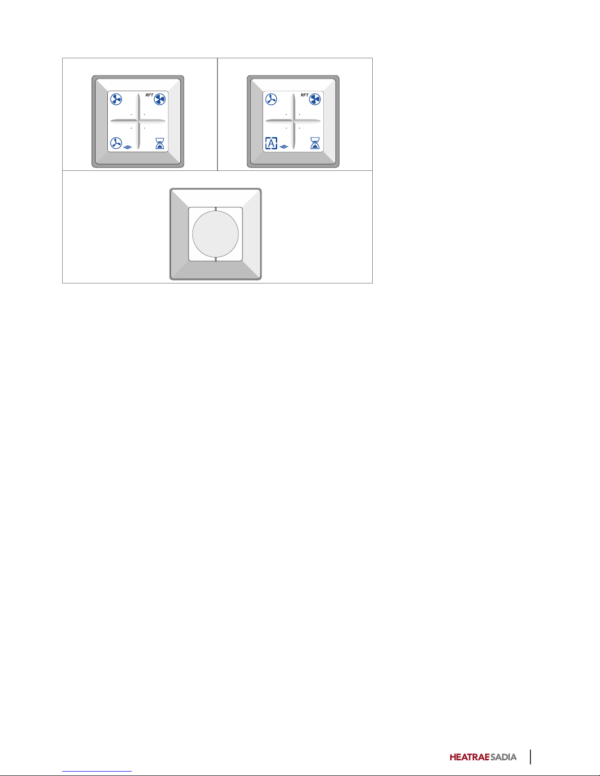
The ventilation unit has several pre-programmed modes.
A number of control switches are available for active
adjustment to the right mode/ventilation capacity:
1. Wireless control switch with three settings and timer
function.
2. Wireless control switch with two settings, automatic
mode and timer function.
3. Wired three-position switch for installation.
A combination of the above options.
You can pair a maximum of 20 wireless control switches
and/or sensors with a Heatrae Sadia ventilation unit or
system.
3.3. Sensors
The ventilation unit can be controlled by the following
available sensors:
●RFT CO2 sensor; 230 V
●RFT RV sensor; battery-powered
●RF-PIR BAT battery-powered.
For pairing or unpairing a wireless sensor with the unit,
see Pairing and unpairing wireless devices and sensors on
page 15.
3.4. Pairing and unpairing wireless
devices and sensors
3.4.1. Pairing wireless devices
Pairing a wireless control switch should be done in the
vicinity of the ventilation unit.
a) Switch off power to the ventilation unit, wait
15 seconds, and then switch on power again.
b) Within two minutes, press two diagonally opposite
buttons at the same time on the control switch.
The control switch is now paired with the ventilation unit.
For information about pairing and unpairing optional
controls, see the documentation included with the
controls.
3.4.2. Unpairing RF devices
Unpairing a wireless control switch should be done in the
vicinity of the ventilation unit.
a) Switch off power to the ventilation unit, wait
15 seconds, and then switch on power again.
b) Within two minutes, press the four buttons of the
control switch at the same time.
Now the ventilation unit will no longer respond to the
control switch(es). Unpairing one control switch
automatically unpairs all switches, controls and sensors.
15

3.4.3. Pairing wireless sensors
Pair wireless sensors with the ventilation unit as follows:
a) Disconnect power to the ventilation unit by pulling
out the plug from the power socket.
b) Wait for at least 15 seconds.
c) Restore power to the ventilation unit by reinserting
the plug in the power socket.
d) Ensure that a pairing message is sent from the
sensor within two minutes after power to the
ventilation unit is switched on. For more information,
consult the documentation provided with the
relevant sensor.
The sensor is paired and the ventilation unit briefly
changes speed to confirm the pairing. The ventilation
unit is now ready to respond to the signals of the wireless
sensor.
3.4.4. Unpairing wireless sensors
The wireless sensors can only be unpaired at the same
time as a wireless control. For more information, see the
procedure Unpairing wireless devices.
Note
After unpairing, all wireless devices (switches and/or
sensors) must be paired with the ventilation unit
again.
16
4. Inspection and
maintenance
Proper functioning of the ventilation system, its capacity
and its service life can only be assured if the system is
inspected and maintained in accordance with the
following instructions. These instructions are based on
normal operating conditions.
ä Caution!
If the ventilation system is being used under harsh
operating conditions or in a very dirty environment,
extra maintenance may be required.
4.1. Inspection and maintenance
schedule
Inspection schedule User Installer
G3 filter
Check for soiling
1 week —
G4 filter 9 months 1 year
F7 filter 6 months 1 year
Ventilation unit Check for soiling and leakage 6 months 1 year
Motor module Check for soiling/imbalance — 1 year
Bypass valve/Frost valve Check functioning and for soiling — 1 year
Heat exchanger Check for soiling — 1 year
Air valves Check for soiling 3 months 1 year
Ducts Check for soiling — 4 years
Maintenance schedule User Installer
G3 filter Clean (first 3 months) 1 week Where necessary
Replace (with G4 or F7) 3 months Where necessary
G4 filter Clean 9 months Where necessary
Replace 18 months Where necessary
F7 filter Clean 6 months Where necessary
Replace 12 months Where necessary
Insect filter Clean 12 months Where necessary
Ventilation unit Clean condensate hose — 1 year
Fan module Clean — 4 years
Heat exchanger Clean — 1 year
Bypass valve/Frost valve Clean — 1 year
Air valves Clean 3 months 1 year
Ducts Clean — 8 years
17
4.2. Inspecting, cleaning and replacing
filters
Note
The HRU ECO 4 comes with G3 filters as standard.
These filters are very suitable for use as "construction
dust filters" after initial completion of the dwelling.
After around three months, these filters should be
replaced with G4 or F7 filters.
ä Caution!
G4 and F7 filters can be cleaned once, after which
they must be replaced at the next maintenance
interval.
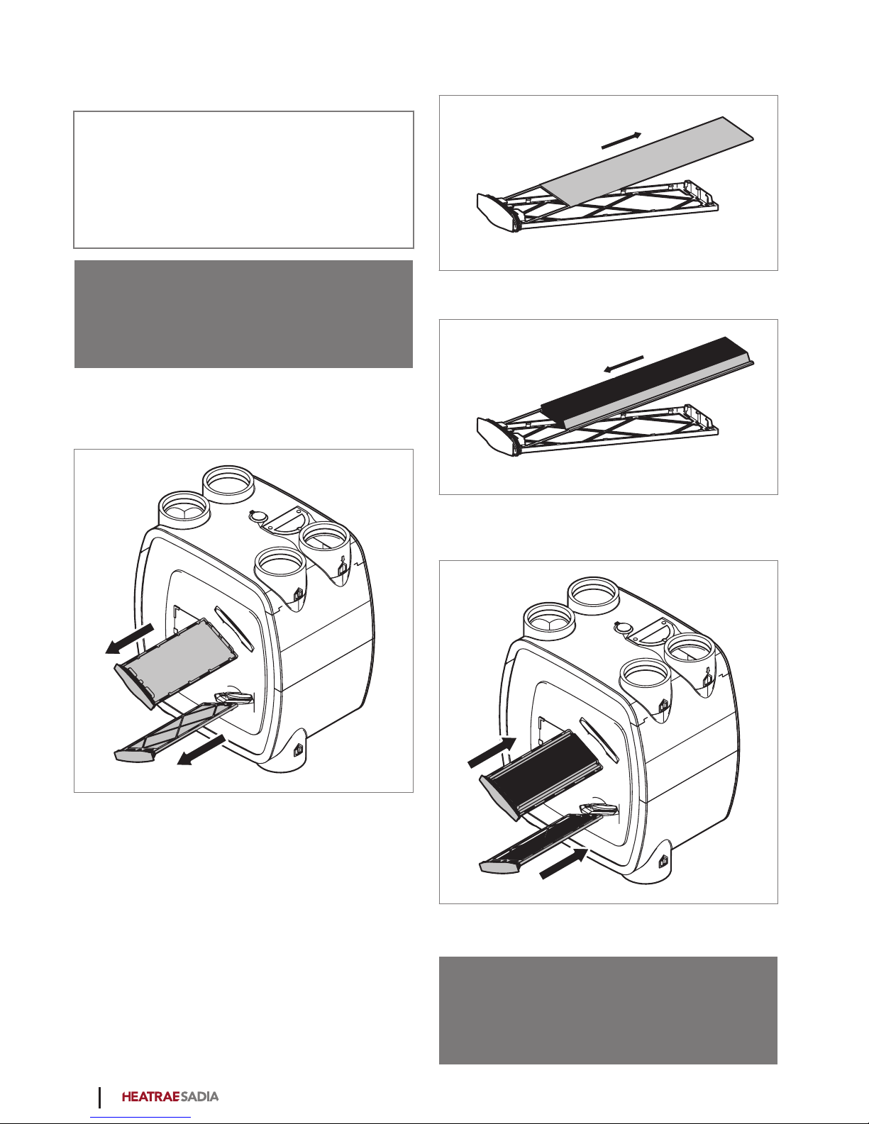
Inspect and clean or replace the filters as follows:
a) Disconnect power to the ventilation unit.
b) Remove both filter holders.
c) Visually inspect the filters for soiling. If the filters are
dirty, they must be cleaned or replaced.
d) Clean or replace the filters. It is possible to clean the
filters by using a vacuum cleaner gently.
e) If the filter is to be replaced, remove it from the filter
holder.
f) Fit the new filter in the filter holder.
g) Place both filter holders back into the ventilation
unit.
h) Restore power to the ventilation unit.
ä Warning!
HRU ECO 4 should always be fitted with the
appropriate filters. Without filters, the appliance can
be irreparably damaged.
18
4.2.1. Resetting the filter indication
After cleaning or replacing the filter, you can reset the
dirty filter indication:
●To perform the reset, you must first switch off power
to the ventilation unit, wait 15 seconds, and then
restore power to the unit.
You then have 10 minutes to reset the filter indication as
described below:
●Wired switch: Turn the wired control switch to a
different setting four times, with a pause of at least 6
seconds each time.
●Wireless control switch: Press two adjacent buttons
on the control switch at the same time.
ä Warning!
HRU ECO 4 should always be fitted with the
appropriate filters. Without filters, the appliance can
be irreparably damaged.
Note
The dirty filter indication cannot be reset via the
control panel.
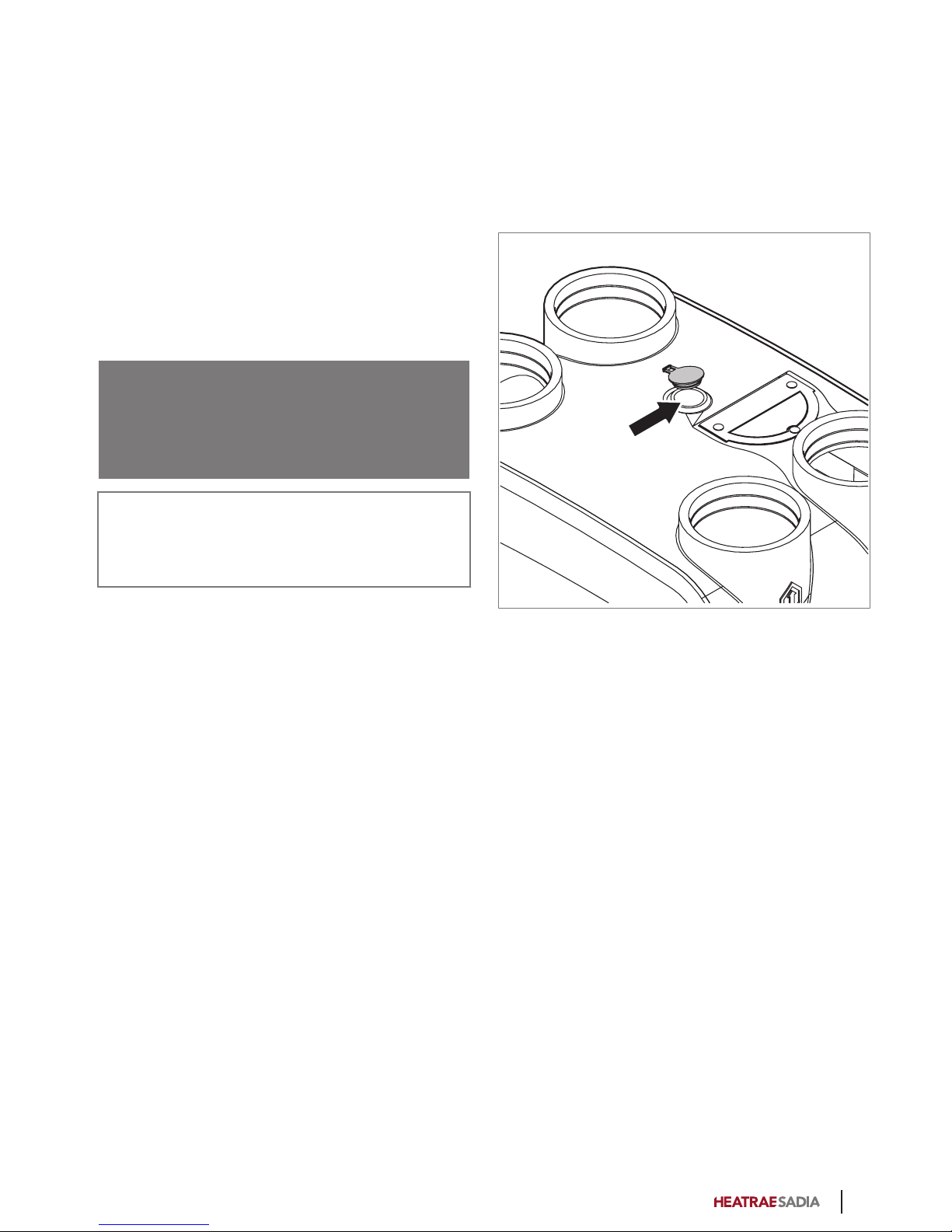
4.3. Cleaning the insect filter
The insect filter must be cleaned once per year. This can
be done by the user.
a) Remove the plug from the power socket or switch off
the ventilation unit.
b) Remove the yellow cap on the top of the ventilation
unit.
c) Then insert the hose of a vacuum cleaner in the hole
and switch on the vacuum cleaner. Any insects and
other soiling in the filter will be removed by the
vacuum cleaner.
d) Replace the yellow cap.
e) Put the HRU ECO 4 back into use by reinserting the
plug into the power socket.
19

4.4. Inspecting and cleaning air valves
Check the air valves regularly (around once every three
months) for soiling. If the air valves are dirty, they must be
cleaned.
ä Caution!
When removing or replacing air valves and grilles,
watch out for protruding duct sections. These can be
very sharp.
ä Caution!
When cleaning, do not adjust the air valve settings,
and replace the valves in their original ducts.
Proceed as follows to clean the air valves.
In case of light soiling, wipe the valves clean with a
slightly damp cloth. If necessary, use a solution of a mild
cleaning agent, such as washing-up liquid or all-purpose
cleaner.
If the valves are soiled with stubborn deposits, remove
them entirely from the duct.
a) Remove the foam rubber gaskets.
b) Fully immerse the valves in a solution of a mild
cleaning agent, such as washing-up liquid or all-
purpose cleaner. If necessary the valves can be
cleaned in a dishwasher.
c) Wipe off the valves with a cloth or a soft brush.
d) Dry the valves. Fit the foam rubber gaskets back on
the valves.
e) Place each valve back in the duct where it came
from.
4.5. Wireless device maintenance
The wireless control switch is battery powered. Under
normal usage conditions, the battery has an estimated
service life of around 7 years. When the battery is empty,
the control switch will stop working and the ventilation
unit will no longer respond to manual operation. The
battery (type CR2032 3V) must then be replaced. Inserting
the battery incorrectly may damage the product. The
batteries should not be exposed to excessive heat in the
form of direct sunlight, fire, etc.
It is not necessary to pair the control switch again.
20
Other manuals for HRU ECO 4
3
Table of contents
Other Heatrae Sadia Fan manuals


Popular Fan manuals by other brands

Teesa
Teesa TSA8022 owner's manual

Sabiana
Sabiana Carisma Fly CVP-ECM Installation, use and maintenance manual

Fanimation
Fanimation Belleria FP4320 Series Specification sheet

Carrier
Carrier Idrofan 42GR ATM installation instructions

Vents
Vents TT PRO user manual

Craftmade
Craftmade Cecilia CC52 installation guide


