BESTEK DNP-851 User manual

1
Network Security System
DNP-851
Always at the forefront of innovation
User Manual
2
This publication contains information that is protected by copyright. No part of it may be reproduced in any
form or by any means or used to make any transformation adaptation without the prior written permission
from the copyright holders.
This publication is provided for informational purposes only. The manufacturer makes no representations or
warranties with respect to the contents or use of this manual and specifically disclaims any express or implied
warranties of merchantability or fitness for any particular purpose. The user will assume the entire risk of the
use or the results of the use of this document. Further, the manufacturer reserves the right to revise this
publication and make changes to its contents at any time, without obligation to notify any person or entity of
such revisions or changes.
© 2011. All Rights Reserved.
All trademarks and registered trademarks of products appearing in this manual are the properties of their
respective holders.
This equipment has been tested and found to comply with the limits for a Class A digital device, pursuant to
Part 15 of the FCC rules. These limits are designed to provide reasonable protection against harmful interference
when the equipment is operated in a residential installation. This equipment generates, uses, and can radiate
radio frequency energy and, if not installed and used in accordance with the instruction manual, may cause
harmful interference to radio communications. However, there is no guarantee that interference will not occur
in a particular installation. If this equipment does cause harmful interference to radio or television reception,
which can be determined by turning the equipment off and on, the user is encouraged to try to correct the
interference by one or more of the following measures:
Reorient or relocate the receiving antenna.
Increase the separation between the equipment and the receiver.
Connect the equipment into an outlet on a circuit different from that to which the receiver is connected.
Consult the dealer or an experienced radio TV technician for help.
Notice:
1. The changes or modifications not expressly approved by the party responsible for compliance could void
the user’s authority to operate the equipment.
2. Shielded interface cables must be used in order to comply with the emission limits.
Copyright
Trademarks
FCC and DOC Statement on Class A
3
1. Warranty does not cover damages or failures that are raised from misuse of the product, inability to use the
product, unauthorized replacement or alteration of components and product specifications.
2. The warranty is void if the product has been subject to physical abuse, improper installation, modification,
accidents or unauthorized repair of the product.
3. Unless otherwise instructed in this user’s manual, the user may not, under any circumstances, attempt to
perform service, adjustments or repairs on the product, whether in or out of warranty. It must be returned
to the purchase point, factory or authorized service agency for all such work.
4. We will not be liable for any indirect, special, incidental or consequential damages to the product that has
been modified or altered.
It is quite easy to inadvertently damage your PC, system board, components or devices even before installing
them in your system unit. Static electrical discharge can damage computer components without causing any
signs of physical damage. You must take extra care in handling them to ensure against electrostatic build-up.
1. To prevent electrostatic build-up, leave the system board in its anti-static bag until you are ready to install
it.
2. Wear an antistatic wrist strap.
3. Do all preparation work on a static-free surface.
4. Hold the device only by its edges. Be careful not to touch any of the components, contacts or connections.
5. Avoid touching the pins or contacts on all modules and connectors. Hold modules or connectors by their
ends.
Important:
Electrostatic discharge (ESD) can damage your processor, disk drive and other
components. Perform the upgrade instruction procedures described at an ESD
workstation only. If such a station is not available, you can provide some ESD protection
by wearing an antistatic wrist strap and attaching it to a metal part of the system chassis.
If a wrist strap is unavailable, establish and maintain contact with the system chassis
throughout any procedures requiring ESD protection.
Warranty
Static Electricity Precautions

4
To avoid damage to the system:
• Use the correct AC input voltage range.
To reduce the risk of electric shock:
• Unplug the power cord before removing the system chassis cover for installation or servicing. After installation
or servicing, cover the system chassis before plugging the power cord.
Battery:
• Danger of explosion if battery incorrectly replaced.
• Replace only with the same or equivalent type recommend by the manufacturer.
• Dispose of used batteries according to local ordinance.
Before using the system, prepare basic system components.
If the system comes as a barebone; that is, none of the key components, including processor, memory, and hard
drive has been pre-installed as part of your purchase, you will need to at least ensure a compatible counterpart
is located and installed.
You will also need a few external system peripherals intended for the use of the system, a common pool with
at least a keyboard, a mouse, and a monitor is thus suggested.
Safety Measures
Before Using the
System
5
Table of Content
Copyright ....................................................................................................................................................................
2
Trademarks ....................................................................................................................................................................
2
FCC and DOC Statement On Class A.............................................................................................................................. 2
Warranty ........................................................................................................................................................................ 3
Static Electricity Precautions......................................................................................................................................... 3
Safety Measures ............................................................................................................................................................ 4
Before Using the System Board..................................................................................................................................... 4
Table of Content ............................................................................................................................................................ 5
Chapter 1 General Information
1.1 Main
Feature ........................................................................................................................................................... 7
1.2
Specifications .......................................................................................................................................................
8
1.3 Indicators and Features .................................................................................................................................... 9
Chapter 2 Preparation
2.1 Before You Begin .....................................................................................................................................11
2.2
Precautions.........................................................................................................................................................
11
2.3 Open The Top Cover
...........................................................................................................................................
12
2.4 Adding 2.5” HDD/SSD ........................................................................................................................................ 13
2.5 Adding Memory............................................................................................................................................... 14
2.6 Adding SATADOM ........................................................................................................................................... 15
2.7 Adding miniPCIe ............................................................................................................................................. 16
Chapter 3 Operation
3.1 Turning On/Off The System.............................................................................................................................. 18
3.2 Installing
Operating System & Drivers...........................................................................................................19
3.3 Understanding LED Indicators ........................................................................................................................ 20
Chapter 4 BIOS Setup
4.1 Entering Setup ................................................................................................................................................ 23
4.2 Getting Help.................................................................................................................................................... 23
4.3 Control Keys.................................................................................................................................................... 23
4.4 The Main Menu............................................................................................................................................... 24
4.5 The Advanced Menu........................................................................................................................................ 25
4.6 The Chipset Menu..................................................................................................................................................... 30
4.7 The Security Menu .......................................................................................................................................... 32
4.8 The Boot Menu................................................................................................................................................ 32
4.9 The Save and Exit Menu .................................................................................................................................. 33
6
Chapter 1
General Information
7
Processor Performance
DNP-850 is an entry level Desktop Network Security Platform with onboard Intel®Celeron® Braswell Quad-
Core N3160 Processor, 1.60GHz base frequency as it is, boasting the fan-less feature with only 6W TDP.
8GB Memory for 64bit OS
The DDR3 SO-DIMM slot is designed to carry up to 8GB DDR3L 1066/1333/1600MHz SDRAM with Non-ECC
support, ideally facilitating applications that demand total memory capacity for the use in 64bit OS, beyond
the 4GB barrier inherent in the 32bit OS.
Four Gigabit LAN Ports
The four onboard Intel® Gigabit LAN Controllers (i210-AT & i211-AT) are the cores of the platform to deliver
outstanding network performance with optional one-pair ByPass ready on request.
True Fan-less Design
The platform carries one fan-less heat-dissipater over processor, adjusting the thermal chamber through
the use of one thermal pad against chassis that offers also space for one internal 2.5” SATA drive, suggesting
a wide variety of software development and deployment.
List of Key Features
Onboard Intel® Celeron® Braswell Quad-Core N3160 1.60GHz Processor
One DDR3L SO-DIMM Slot up to 8GB
Two Intel® i211-AT GbE LAN Ports
Two Intel® i210-AT GbE LAN Ports with Optional 1-Pair ByPass
One Internal 2.5” SATA Drive Bay
Onboard eMMC
Two Front USB 3.0 Ports
One Front Console Port
One Half-Sized miniPCIe Slot with USB signal
+12Vdc Power Input via external adapter
1* Optional HDMI Port
1.1 Main Feature
8
Core Engine
Processor
Onboard Intel® Braswell Celeron N3160 (6W) Quad Core Processor
Memory
1x DDR3L 1333 Non-ECC Unbuffered Memory up to 8GB
Ethernet
Controller
2x Intel® i211-AT GbE Ports + 2x Intel® i210-AT GbE Ports with Bypass
Storage
SATA
1x Internal 2.5” SATA3 Drive Bay + 1x SATADOM
eMMC
1x Onboard eMMC
Front I/O
Indication
1x Power LED, 1x HDD LED, 1x Bypass LED, 4x LAN Activity LEDs, 4x LAN Speed LEDs
Rear I/O
Power Inlet
1x 12V DC Jack
LAN
4x RJ45 1G LAN Ports
Console
1x RJ45 Type Console Port
USB
2x USB 3.0 Ports
Display
1x HDMI
Switch
1x Push Button Power Switch
Expansion
miniPCIe
1x Slot with (USB 2.0)
Power
Type
External 12V@40W Power Adaptor, 100-240Vac, 50-60Hz
Cooling
CPU Cooling
Passive CPU Heatsink (with optional cooling fan)
Other
H/W Monitoring
Monitor temperature, voltage, and fan speed, auto-throttling control at CPU overheat
Environment
Operating Temp.
0oC ~ 40oC
Storage Temp.
-20oC ~ 70oC
Humidity
10% ~ 90% (Non-Condensing)
Mechanical
Dimension
300mm (W) x 145mm (D) x 44mm (H)
1.2 Specifications

9
►Front View
►Rear View
1.3 Indicators & Features

10
Chapter 2
Preparation
11
A stable and clean working environment are essential. Dust and dirt can get into components and cause a
malfunction. Use containers to keep small components separated.
Adequate lighting and proper tools can prevent you from accidentally damaging the internal components. Most
of the procedures that follow require only a few simple tools, including the following:
A Philips screwdriver
A flat-tipped screwdriver
A set of jewelers Screwdrivers
A grounding strap
An anti-static pad
Using your fingers can disconnect most of the connections. It is recommended that you do not use needle-nosed
pliers to disconnect connections as these can damage the soft metal or plastic parts of the connectors.
Before working on internal components, make sure that the power is off. Ground yourself before touching any
internal components, by touching a metal object. Static electricity can damage many of the electronic
components. Humid environment tend to have less static electricity than dry
environments.
A grounding strap is
warranted whenever danger of static electricity exists.
Computer components and electronic circuit boards can be damaged by discharges of static electricity. Working
on the computers that are still connected to a power supply can be extremely dangerous. Follow the guidelines
below to avoid damage to your computer or yourself:
Always disconnect the unit from the power outlet whenever you are working inside the case.
If possible, wear a grounded wrist strap when you are working inside the computer case. Alternatively,
discharge any static electricity by touching the bare metal chassis of the unit case, or the bare
metal body
of any other grounded appliance.
Hold electronic circuit boards by the edges only. Never touch the components on the board unless it is
necessary to do so. Do not flex or stress the circuit board.
Leave all components inside the static-proof packaging that they shipped with until they are ready for
installation.
Use correct screws and do not over tighten screws.
2.1 Before You Begin
12
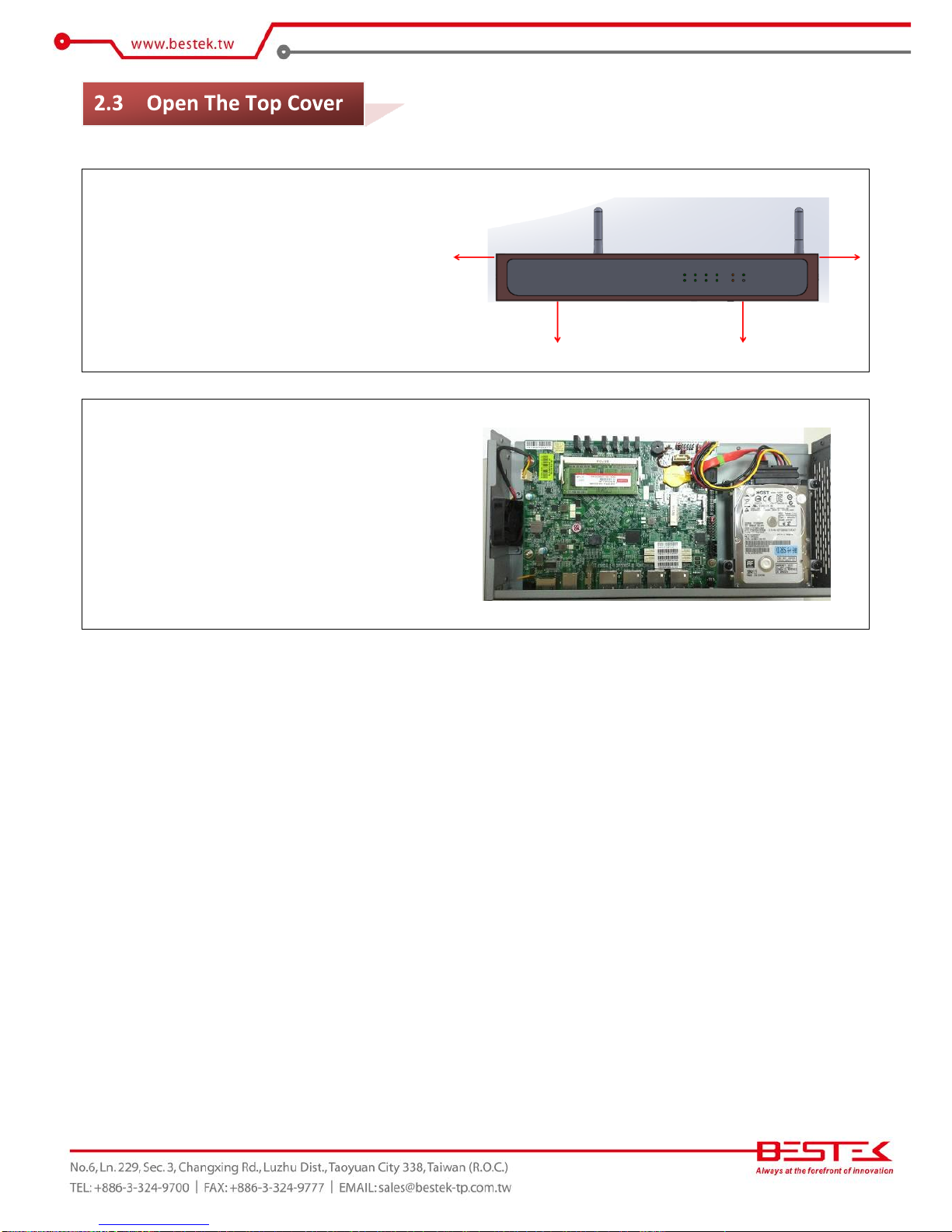
Please remove four screws as indicated in
the right figure, and slide out the top cover
(towards the front direction).
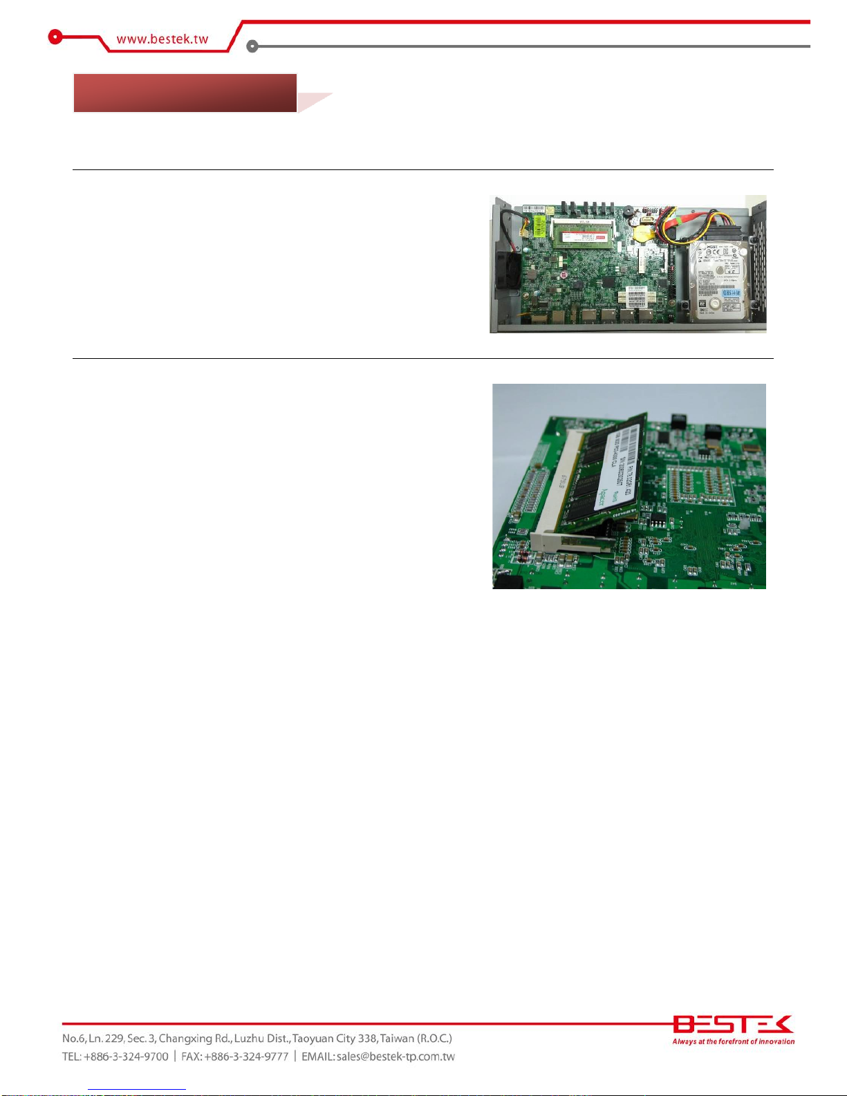
This is the inside view of DNP-851, where
SO-SIMM RAM and 2.5” HDD have been
added. In case your DNP-851 does not
come with RAM and HDD, please refer to
the following sections for details.

13
(1) Acquire the 2.5” HDD/SSD bracket from the build by removing
the screws fastening on this bracket. Complete the assembly of
this bracket and your 2.5” HDD/SSD as the figure on the right.
Remember to conjoin the green cable for grounding procedure
at step (2).
(2) Move the HDD/SSD subset to the chassis, on the four standoffs,
making sure the HDD/SSD I/O is along motherboard LED side.
Add four screws to secure this subset in the place. Also adhere
the green cable to one of the motherboard screw and have it
tied at that place.
(3) Find the SATA cable and SATA power cable and deploy the cable
set as in the figure on the right.
14
This is the step to go through if it is only the PCI cards to be accessed.
(1) The figure on the right shows the place where a DDR3L SO-DIMM
has been added.
(2) To add one memory in case nothing is present, please add your
memory module as indicated in the figure on the right; that is,
insert the golden finger into the socket, also making sure
memory key is latched, press the other side down until the
module is firmly snapped.
2.5 Adding Memory

15
DNP-851 supports only right-angled SATADOM. Please consult your dealer for details of availability.
(1) Find the SATADOM and power cable on the right.
(2) Add this power cable on the corresponding connector on
SATADOM module.
(3) Add SATADOM on the other SATA connector (next to LED), and
have the power cable on the HDD power connector.
2.6 Adding SATADOM

16
DNP-851 supports only half-sized miniPCIe (USB signal only). Please consult your dealer for details of
availability.
(1) Find the miniPCIe socket (next to SATA connector). Insert
miniPCIe golden finger into the socket, press the other side
down, and add one or two screws to finish the installation.
2.7 Adding miniPCIe
17
Chapter 3
Operation

18
As in the figure below (the rear side of the DNP-851), add your cables such as USB keyboard and USB mouse
on the USB ports (Green circles). Manage to connect a monitor on the HDMI port. Leave the 12Vdc power as
the last cable to be added, right on the DC-in as indicated below (Blue circle).
Turn On the Power
In some cases, depending on whether a BIOS setting has been configured to allow immediate power-on upon
the delivery of power, system might come right up. Please refer to BIOS section for details as to “PWRON After
PWR-Fail”. Have you intended to bring it down, simply press once the power switch (the round push button
with yellow circle), or press and hold for 4 seconds, to reach that goal.
However, in most occasions, without such abrupt event as stated above, simply press once on the Power
Switch to turn on the system.
Turn Off the Power
There are a few scenarios where different approaches to turn off the system are recommended as below:
(1) Operating System: Regardless of the type of operating system in the hard drive, users should find no difficulty to
follow the standard power off procedure as is available within the said operating system. Modern operating systems
such as Microsoft® Windows® or Linux are usually designed with similar power scheme, where once initiated,
should bring the power down after a not so long and complicated shutdown process.
(2) BIOS: In case users intend to directly shutdown the system after a brief check within BIOS setup menu, simply press
once the power switch, or press and hold for 4 seconds, to achieve that goal.
(3) Software catastrophe: In the event that a software testing reaches a point of malfunction or endless loop, where no
restart or even user control is possible in software manner, it is suggested to simply press and hold the power
switch for 4 seconds to disengage the power.
Please never try to unplug the adapter cable without trying the above approaches, as abruptly detaching the
adapter cable while system power is still on might introduce unexpected power spikes or system inconsistency
due to data corruption and hence is the least suggested way to deploy.
Power LED
The power LED is integrated within the power switch, and shall come lit constant ON at system start.
HDD LED
The red LED is HDD LED which shall blink in the wake of hard drive.
3.1 Turning On/Off The System

19
Bypass LED
This LED should go green when Bypass function is disabled, and red when enabled.
First screen & Optimal BIOS Setting
Once the system successfully boots up, it shall activate display signal on monitor, disclosing some system
information as checkpoints for debugging, thereafter users, has this been the first time to boot the unit, are
encouraged to bring up BIOS setup menu to at least load the optimal BIOS setting, as the first thing to do at
power on. Please refer to the BIOS section for substantial details.
Confirm the Hard Drive List
The system is designed to allow booting from a variety of internal devices, including USB pen drive and SATA
drive (such as SATA HDD/SSD or SATADOM). Given the tiny footprint and slow performance of USB pen drive,
SATA drive is a better choice to carry operating system and can be found in the detected drive list, in the
section of IDE Configuration.
In the event that a particular SATA device is not detected and prompted in the device list, hardly would the
system boot from it. Please turn off the system, check or re-apply the SATA cable and SATA power cable to
ensure an appropriate connection.
3.2 Installing Operating System & Drivers
20
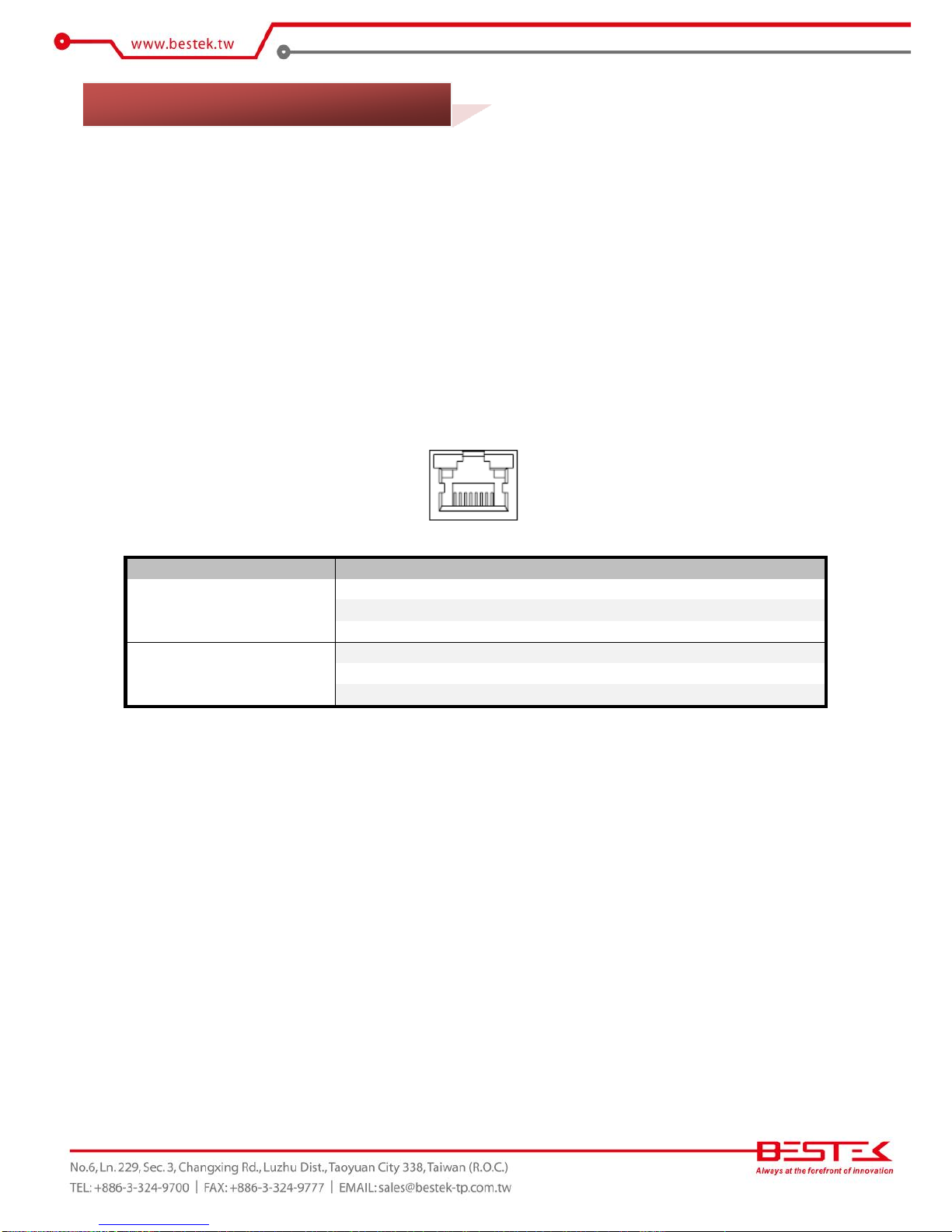
Activity LED
The left LED is LAN Port Activity LED, with three different indication status:
(1) Constant Yellow: Network is connected.
(2) Blinking Yellow: Network activity is on-going.
(3) Off: Network is not connected.
LAN Speed LED
The right LED is LAN Port Speed LED, with three different speeds:
(1) Amber: 1000 Speed
(2) Green: 100 Speed
(3) Off: 10 Speed.
Summary Table
LED
Color
State
Description
RJ45 NIC Linkage
(Left Side)
Yellow
On
LAN linked
Yellow
Blinking
LAN accessing
Off
Off
No LAN linked
RJ45 NIC Mode
(Right Side)
Amber
On
Gigabit mode
Green
On
100M mode
Off
Off
10M mode
3.3 Understanding LAN Indicators
This manual suits for next models
1
Table of contents
Popular Network Hardware manuals by other brands


NetComm
NetComm Freshtel NB9W Upgrade instructions

EasyIO
EasyIO Sedona quick start

Fujitsu
Fujitsu MB15F74UL datasheet

D-Link
D-Link DNS-313 Quick installation guide

Ubiquiti
Ubiquiti UniFi Dream Machine Pro quick start guide

Extron electronics
Extron electronics MAAP Active Modules VCM 100 MAAP Specification sheet


