BESTEK BES-2202 User manual

1
Rack Mount System
BES-2202
Always at the forefront of innovation
User Manual

2
This publication contains information that is protected by copyright. No part of it may be reproduced in any
form or by any means or used to make any transformation adaptation without the prior written permission
from the copyright holders.
This publication is provided for informational purposes only. The manufacturer makes no representations or
warranties with respect to the contents or use of this manual and specifically disclaims any express or implied
warranties of merchantability or fitness for any particular purpose. The user will assume the entire risk of the
use or the results of the use of this document. Further, the manufacturer reserves the right to revise this
publication and make changes to its contents at any time, without obligation to notify any person or entity of
such revisions or changes.
© 2011. All Rights Reserved.
All trademarks and registered trademarks of products appearing in this manual are the properties of their
respective holders.
This equipment has been tested and found to comply with the limits for a Class A digital device, pursuant to
Part 15 of the FCC rules. These limits are designed to provide reasonable protection against harmful
interference when the equipment is operated in a residential installation. This equipment generates, uses,
and can radiate radio frequency energy and, if not installed and used in accordance with the instruction
manual, may cause harmful interference to radio communications. However, there is no guarantee that
interference will not occur in a particular installation. If this equipment does cause harmful interference to
radio or television reception, which can be determined by turning the equipment off and on, the user is
encouraged to try to correct the interference by one or more of the following measures:
Reorient or relocate the receiving antenna.
Increase the separation between the equipment and the receiver.
Connect the equipment into an outlet on a circuit different from that to which the receiver is connected.
Consult the dealer or an experienced radio TV technician for help.
Notice:
1. The changes or modifications not expressly approved by the party responsible for compliance could void
the user’s authority to operate the equipment.
2. Shielded interface cables must be used in order to comply with the emission limits.
Copyright
Trademarks
FCC and DOC Statement on Class A

3
1. Warranty does not cover damages or failures that are raised from misuse of the product, inability to use
the product, unauthorized replacement or alteration of components and product specifications.
2. The warranty is void if the product has been subject to physical abuse, improper installation, modification,
accidents or unauthorized repair of the product.
3. Unless otherwise instructed in this user’s manual, the user may not, under any circumstances, attempt to
perform service, adjustments or repairs on the product, whether in or out of warranty. It must be
returned to the purchase point, factory or authorized service agency for all such work.
4. We will not be liable for any indirect, special, incidental or consequential damages to the product that has
been modified or altered.
It is quite easy to inadvertently damage your PC, system board, components or devices even before installing
them in your system unit. Static electrical discharge can damage computer components without causing any
signs of physical damage. You must take extra care in handling them to ensure against electrostatic build-up.
1. To prevent electrostatic build-up, leave the system board in its anti-static bag until you are ready to install
it.
2. Wear an antistatic wrist strap.
3. Do all preparation work on a static-free surface.
4. Hold the device only by its edges. Be careful not to touch any of the components, contacts or connections.
5. Avoid touching the pins or contacts on all modules and connectors. Hold modules or connectors by their
ends.
Important:
Electrostatic discharge (ESD) can damage your processor, disk drive and other
components. Perform the upgrade instruction procedures described at an ESD
workstation only. If such a station is not available, you can provide some ESD
protection by wearing an antistatic wrist strap and attaching it to a metal part of the
system chassis. If a wrist strap is unavailable, establish and maintain contact with the
system chassis throughout any procedures requiring ESD protection.
Warranty
Static Electricity Precautions
4
To avoid damage to the system:
• Use the correct AC input voltage range.
To reduce the risk of electric shock:
• Unplug the power cord before removing the system chassis cover for installation or servicing. After
installation or servicing, cover the system chassis before plugging the power cord.
Battery:
• Danger of explosion if battery incorrectly replaced.
• Replace only with the same or equivalent type recommend by the manufacturer.
• Dispose of used batteries according to local ordinance.
Before using the system, prepare basic system components.
If the system comes as a barebone; that is, none of the key components, including processor, memory, and
hard drive has been pre-installed as part of your purchase, you will need to at least ensure a compatible
counterpart is located and installed.
You will also need a few external system peripherals intended for the use of the system, a common pool with
at least a keyboard, a mouse, and a monitor is thus suggested.
Safety Measures
Before Using the System
5
Table of Content
Copyright ....................................................................................................................................................................
2
Trademarks ....................................................................................................................................................................
2
FCC and DOC Statement On Class A.............................................................................................................................. 2
Warranty ........................................................................................................................................................................ 3
Static Electricity Precautions......................................................................................................................................... 3
Safety Measures ............................................................................................................................................................ 4
Before Using the System Board..................................................................................................................................... 4
Table of Content ............................................................................................................................................................ 5
Chapter 1 General Information
1.1 Main Feature
........................................................................................................................................................... 7
1.2
Specifications .......................................................................................................................................................
8
1.3 System Layout ................................................................................................................................................... 9
1.4 Indicators and Features .................................................................................................................................. 10
Chapter 2 Preparation
2.1 Before You Begin...................................................................................................................................... 12
2.2 Precautions
.........................................................................................................................................................
12
2.3 Open Up Top Cover
.............................................................................................................................................
13
2.4 Accessing Processor & Memory........................................................................................................................ 14
2.5 Accessing PCIe Card........................................................................................................................................ 14
2.6 Accessing miniPCIe Card................................................................................................................................. 15
2.7 Adding 3.5” SATA Hard Drive .......................................................................................................................... 16
Chapter 3 Operation
3.1 Turning On The System.................................................................................................................................... 18
3.2 RAID Configuration ............................................................................................................................................ 19
3.3 Installing Operating System & Drivers
........................................................................................................
22
3.4 RAID Interruption ........................................................................................................................................... 23
3.5 Understanding LED Indicators ........................................................................................................................ 24
Chapter 4 BIOS Setup
4.1 Entering Setup ................................................................................................................................................ 27
4.2 Getting Help.................................................................................................................................................... 27
4.3 Control Keys .................................................................................................................................................... 27
4.4 The Main Menu............................................................................................................................................... 28
4.5 The Advanced Menu........................................................................................................................................ 29
4.6 The Chipset Menu..................................................................................................................................................... 31
4.7 The Boot Menu................................................................................................................................................ 32
4.8 The Security Menu .......................................................................................................................................... 33
4.9 The Save & Exit Menu..................................................................................................................................... 34
Chapter 5 Q&A ...................................................................................................................36
6
Chapter 1
General Information

7
Processor Performance
BES-2202 is a rack mount system that is pre-installed with BNX-M67 motherboard, featuring Intel® Q67
chipset, supporting Intel® LGA1155 Celeron®, Pentium®, Core® 2 Duo, and Core® 2 Quad processor, with
Intel® integrated graphic controller. Below is a brief list of available processors as a quick reference:
Celeron® Processor: G540
Pentium® Processor: G850
Core®-i3 Processor: i3-2120
Core®-i5 Processor: i5-2400
Core®-i7 Processor: i7-2600
8GB Memory for 64bit OS
The four Dual Channel DDR3 DIMM slots are designed to carry up to 16GB DDR3 1066/1333MHz SDRAM
with Non-ECC support, ideally facilitating applications that demand total memory capacity for the use in
64bit OS, beyond the 4GB barrier inherent in the 32bit OS.
Expansion Options
Two PCIe 2.0 X8 slots are available for expansion, particularly for applications using PCIe X8 adaptors with
high bandwidth requirements, such as RAID card, eSATA card, USB 3.0 card, or communication card. No
surprise at all would this interface be compatible with other adaptors of smaller build. The onboard
miniPCIe slot is also present as an alternative for slow speed or general function devices, such as
communication, LAN or SATA.
List of Key Features
Intel® Q67 Chipset
Intel® LGA1155 Celeron®, Pentium®, Core®-i3/i5/i7
Four DDR3 RAM Slots up to 16GB
Two Internal 2.5” Drive Bays
DB15 VGA + HDMI + DVI-D
Four USB 2.0 Ports
Two Intel® GbE LAN Ports
Two PCIe 2.0 X8 Slots
One miniPCIe Slot
Compact Dimension of 427x350x87.3mm
1.1 Main Feature

8
Construction
Form Factor
2U Rack Mount Chassis for Micro-ATX Motherboard
Material
Heavy duty cold rolled electroplated steel
Dimension (W x D x H)
Chassis (427 x 350 x 88mm)
Weight
10.0 Kg
Color
Black
Certification
CE/FCC
System
Chipset
Intel® Q67
Processor
Intel® 2nd Generation Core™ i7/i5/i3/ Pentium® / Celeron® Processor
Memory
4x DDR3 1333 DIMM up to 16GB, Non-ECC, Un-buffered Memory
Power
Single 300W Flex-ATX, 100-240Vac, 50-60Hz
Storage
2.5”
2x Internal
Cooling
Air Filtering
Front Side
Fan
1x CPU Fan, 2x 80mm Front Fans
Connectivity
Communication
Onboard 1x Intel® 82579LM + 1x Intel® 82583V PCIe GbE Controllers
Front I/O
1x Power Switch with LED, 2x HDD LEDs
Rear I/O
1x DB15 VGA, 1x DVI-D, 1x HDMI, 2x RJ45, 4x USB 2.0
3x Audio Jacks, 1xAC-in
Expansion Slots
PCIe X8
2x
Environment
Operating Temperature
0 ~ 50oC
Storage Temperature
-20 ~ 70oC
Operating Humidity
0% ~ 90%
Storage Humidity
0% ~ 90%
1.2 Specifications

9
Figure 1.1: System Layout of BES-2202
1.3 System Layout

10
►Front View
►Rear View
1.4 Indicators & Features
11
Chapter 2
Preparation

12
A stable and clean working environment are essential. Dust and dirt can get into components and cause a
malfunction. Use containers to keep small components separated.
Adequate lighting and proper tools can prevent you from accidentally damaging the internal components. Most
of the procedures that follow require only a few simple tools, including the following:
A Philips screwdriver
A flat-tipped screwdriver
A set of jewelers Screwdrivers
A grounding strap
An anti-static pad
Using your fingers can disconnect most of the connections. It is recommended that you do not use
needle-nosed pliers to disconnect connections as these can damage the soft metal or plastic parts of the
connectors.
Before working on internal components, make sure that the power is off. Ground yourself before touching any
internal components, by touching a metal object. Static electricity can damage many of the electronic
components. Humid environment tend to have less static electricity than dry
environments.
A grounding strap is
warranted whenever danger of static electricity exists.
Computer components and electronic circuit boards can be damaged by discharges of static electricity. Working
on the computers that are still connected to a power supply can be extremely dangerous. Follow the guidelines
below to avoid damage to your computer or yourself:
Always disconnect the unit from the power outlet whenever you are working inside the case.
If possible, wear a grounded wrist strap when you are working inside the computer case. Alternatively,
discharge any static electricity by touching the bare metal chassis of the unit case, or the bare
metal body
of any other grounded appliance.
Hold electronic circuit boards by the edges only. Never touch the components on the board unless it is
necessary to do so. Do not flex or stress the circuit board.
Leave all components inside the static-proof packaging that they shipped with until they are ready for
installation.
Use correct screws and do not over tighten screws.
2.1 Before You Begin
2.2
Precautions

13
If you are to install (or change) a processor (or memory module), you need to know how to open up the top
cover. It is not necessary to open up the top cover if it is to add/remove/swap Hard Drive, as both 3.5” Hard
Drive are accessed through the front trays. Please refer to the Hard Drive Tray section for details.
Please remove 3 screws on each side and one screw on the back, as indicated in the places below, prior to any
moving of the top cover. It is recommended to push the top cover backwards so as to detach the cover tongue
out of the snatch-up at front side, before the lift-up or removal of the top cover.
Securing the screws is essential for they would be re-used for the restoration of the top cover, after all
preparation procedures are completed.
2.3
Open Up Top Cover

14
Please refer to the Manual of BNX-M67 motherboard for substantial details as to adding processor, cooler, and
memory.
In case the BES-2202 does not come with any pre-installed PCIe card on the two PCIe X8 slots, these slots
would be your options in case you are bound to add extra features onto the unit.
Always invariably mind the size of the PCIe card to be added against the undoubtedly compact size of the unit.
A perfect fit would be any short card of the speed of PCIe X1/4/8. A PCIe card of length running out of the
preferred range (say 240mm) is not to be considered as a perfect device for the installation. A full-height PCIe
card is in the range of deployment, provided the dimension does not run into any conflict with other parts.
Procedures:
(1) It is assumed that the system is turned off and the top cover is detached before accessing PCIe slot is proceeded.
There are three slot brackets with two holding screws, and they would be removed before any card can be
added.
(2) Detach the two screws holding these two brackets, and gently disengage them off the place.
(3) Add the 2-slot PCIe card onto the slot (horizontally), and the bracket of the card will be sitting on the same place
where the slot brakcet was held.
(4) Put the same two screws right back and the job is completed.
2.4 Accessing Processor & Memory
2.5 Accessing PCIe Card

15
In case the BES-2202 does not come with any pre-installed card on the miniPCIe slot, this slot would be one of
the options in case you are bound to add extra features onto the unit.
The miniPCIe slot is right next to the PCIe X16 slot, as in the yellow box below, and only a full-sized miniPCIe
module is to be added.
Procedures:
(1) It is assumed that the system is turned off and the top cover is detached before accessing PCIe slot is
proceeded.
(2) If a screw is found in the stand-off, please remove the screw.
(3) Align the notch in the card with the socket key and insert the card at a slightly upward angle as shown.
(4) Push down on the card and secure with one screw.
(5) In case the add-on card comes with extra cables to be attached onto devices or chassis, for instance SATA cables
to be attached to Hard Drive or COM cables to be attached to rear I/O, please manage the cables as intructed in
the card manual.
2.6 Accessing miniPCIe Card
16
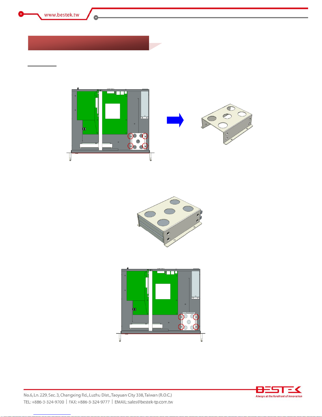
Procedures:
(1) Find the Hard Drive bracket from within the chassis.
(2) Disengage the four screws that secure this bracket right on the chassis.
(3) Add one or two 2.5”drives onto the bracket. If only one drive is to be added, pick a bay as wished.
(4) Add four screws for each drive to complete the subset.
(5) Restore the bracket back to chassis and add four screws to firmly lock this bracket in place.
(6) Apply SATA cable (onto motherboard SATA port) and SATA power cable (from power supply) for each drive.
2.7 Adding 2.5”SATA Hard Drive
17
Chapter 3
Operation
18
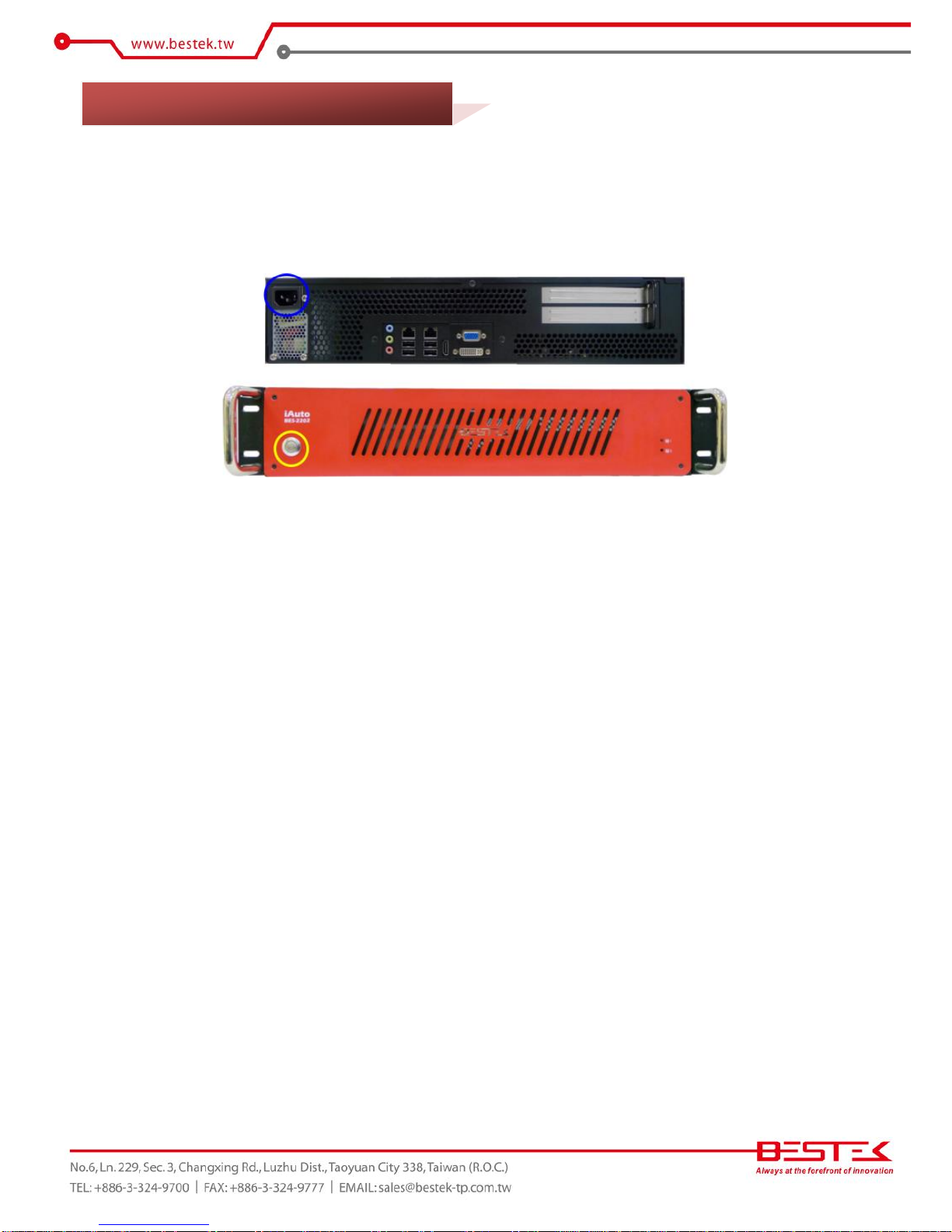
Add your cables, such as USB keyboard, USB mouse, and display cable (VGA, HDMI, or DVI) to control the
system. Leave the AC power cord as the last cable to be added, right on the AC Inlet as indicated below with
blue circle. The AC input range of the built-in Power Supply is 100-240Vac. If your AC input is not within this
range, though rarely possible in fact, it is not compliant with the system and you should not plug in the AC
power cord.
Turn On the Power
In some cases, depending on whether a BIOS setting has been configured to allow immediate power-on upon
the delivery of AC power, system might come right up unexpectedly for no particular reason. Please refer to
BIOS section for details as to “PWRON After PWR-Fail”. Have you intended to bring it down, simply press once
the power switch (located at the right lower corner with yellow circle), or press and hold for 4 seconds, to
reach that goal.
However, in most occasions, without such abrupt event as stated above, simply press once on the Power
Switch to turn on the system.
Power LED
The power switch comes with a built-in LED (to be used as power LED) which shall come lit constant ON at
system start.
HDD LED
Two HDD LEDs can be found on the front red bezel, right next to the Hard Drive trays, and shall blink in the
wake of storage activity of each corresponding HDD. In case one trays is not installed with Hard Drive, the HDD
LED of that trays will not be lit at all.
3.1 Turning On The System

19
First screen & Optimal BIOS Setting
Once the system successfully boots up, it shall activate display signal on monitor, disclosing some system
information as checkpoints for debugging, also known as POST (Power-On-Self-Test) message, thereafter users
are encouraged to bring up BIOS setup menu to at least load the optimal BIOS setting, as the first thing to do
at power on.
Please be reminded that, as one PCIe RAID card has been added on its arrival to user, the RAID Configuration
prompt will show up after system POST message, prior to the BIOS setup menu. Please patiently wait for this
message to walk through before BIOS setup menu comes up thereafter.
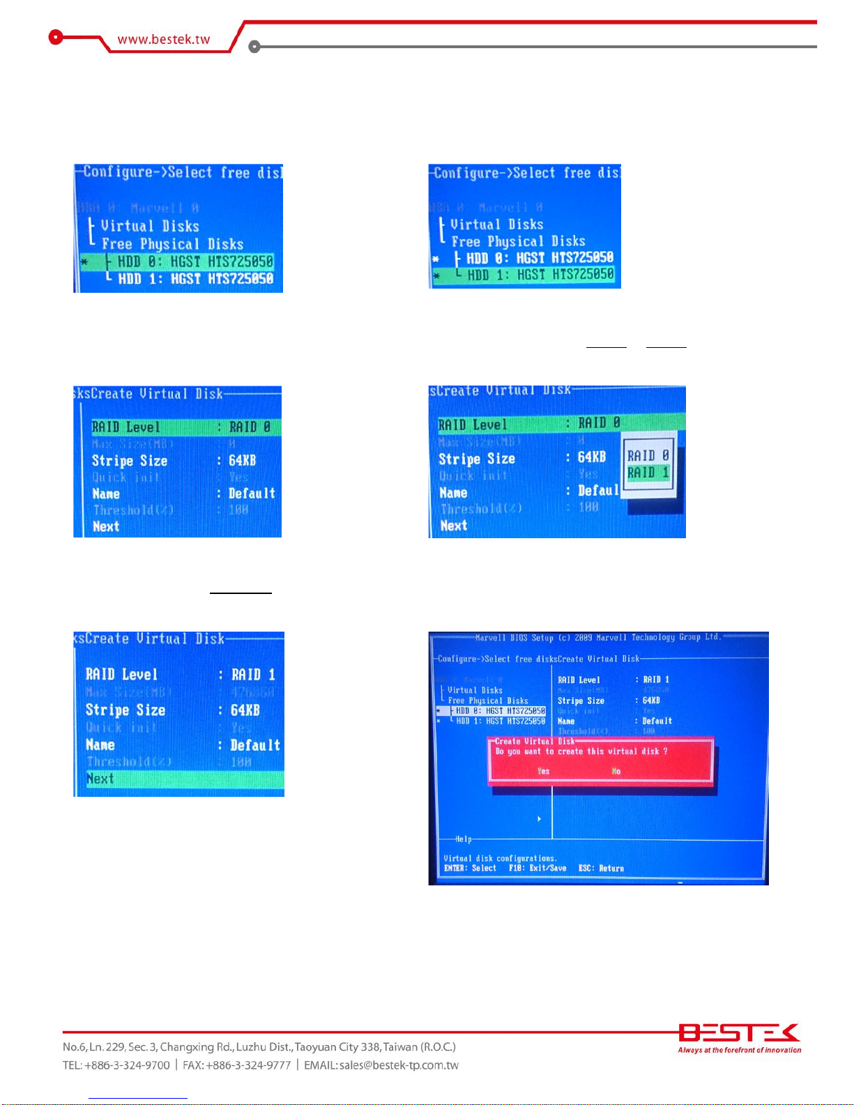
As stated in the previous section that RAID Configuration prompt will show up after system POST message,
this is actually the right moment when user can press on the “Ctrl-M” key combination to bring up the RAID
Configuration Menu (called Marvell BIOS Setup Utility), as given below, where the two 3.5” hard drive in the
trays have been identified by RAID Controller automatically. In the event that one or both hard drives are
missing in the list, please turn off the system and check the HDD trays and SATA cables.
Procedures to configure RAID-1:
(1) Move to HBA 0: Marvell 0 and press “Enter”. Press
“Enter” again to select Configuration Wizard.
(2) Move to the first hard drive.
3.2 RAID Configuration
20
(3) Press “Space” key to select this hard drive. Once
selected, a star sign will be added at the head of the
Hard Drive.
(4) Repeat the same procedure until both hard drives are
selected.
(5) Press “Enter” to start creating RAID volume, where
operation would move to the right pane.
(6) Press “Enter” to select RAID 0 or RAID 1.
(7) Move to select the Stripe Size, and define a RAID
name.
(8) Press “F10” and “Yes” to create the configuration into
RAID controller.
Table of contents
Popular Server manuals by other brands


Home Automation
Home Automation CAMERA SERVER 87A00-1 Installation and user guide

Sun Oracle
Sun Oracle T4BLD Safety and compliance guide

Nortel
Nortel 1000E maintenance

HP
HP ProLiant DL380 G3 with MSA1000 Setup and installation guide

Dell EMC
Dell EMC DP4400 Service Procedures

Dell EMC
Dell EMC PowerEdge R740 Installation and service manual


