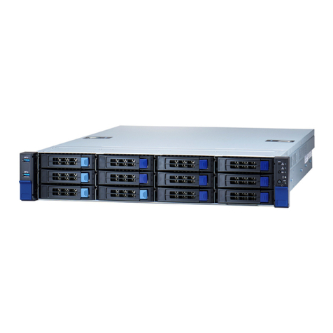
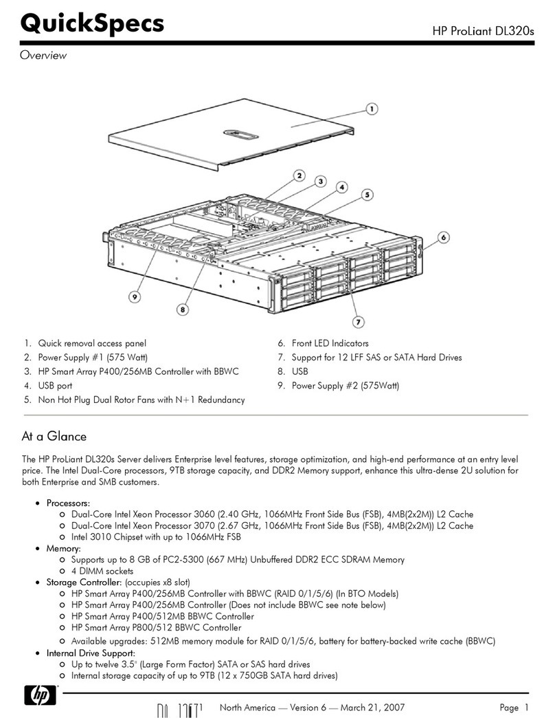
PRIMERGY TX200 S3 User manual

PRIMERGYTX200S3ConfigurationSheets
EDesignSheetoftheRAIDconfiguration
Usethisformtorecordthedefinitionsofthediskgroups(orthephysicalpacks)andthelogical
drivesintheRAIDconfiguration(arrayconfiguration).
FDesignSheet
Usethisformtorecordthesoftwaresettings.
GAccidentSheet
Usethisformtorecordanyfailuresthatoccurinyourserver.
A ConfigurationSheetsofHardware
Usethisformtorecordthehardwareconfigurationandvarioussettingsofyourserver.
BConfigurationSheetsofBIOSSetupUtilityParameters
UsethisformtorecordthesettingsoftheBIOSSetupUtility.
CConfigurationSheetsofRemotemanagementcontroller'sWebinterface
UsethisformtorecordthesettingsoftheRemoteManagementControllerWebinterface.
DTableofSystemresourcemanagement
TheI/Oportaddressthatcanbeselectedwithvariousexpansioncardsisthefollowingtables.
Aboutthismanual
1

Thefollowingexpressionsandabbreviationsareusedtodescribetheproductnamesusedinthismanual.
Productnames
PRIMERGYTX200S3 Thisserver,orserver
Microsoft®WindowsServer®2003R2,StandardEdition WindowsServer2003R2,
StandardEdition Windows
2003
Microsoft®WindowsServer®2003R2,EnterpriseEdition WindowsServer2003R2,
EnterpriseEdition
Microsoft®WindowsServer®2003,EnterpriseEdition WindowsServer2003,
EnterpriseEdition
Microsoft®WindowsServer®2003,StandardEdition WindowsServer2003,Standard
Edition
Microsoft®WindowsServer®2003R2,Standardx64Edition WindowsServer2003R2,
Standardx64Edition
Microsoft®WindowsServer®2003R2,Enterprisex64Edition WindowsServer2003R2,
Enterprisex64Edition
Microsoft®WindowsServer®2003,Standardx64Edition WindowsServer2003,Standard
x64Edition
Microsoft®WindowsServer®2003,Enterprisex64Edition WindowsServer2003,
Enterprisex64Edition
Microsoft®Windows®2000Server Windows2000Server
Microsoft®Windows®2000AdvancedServer Windows2000AdvancedServer
Microsoft®WindowsServer®2003ServicePack SP
Microsoft®Windows®2000ServicePack
■Trademarks
Microsoft,Windows,MS,WindowsServerareregisteredtrademarksoftheMicrosoftCorporationintheUSAandother
countries.
Intel,XeonareregisteredtrademarksortrademarksofIntelCorporationoritssubsidiariesintheUSAandother
countries.
Allotherhardwareandsoftwarenamesusedaretrademarksorregisteredtrademarksoftheirrespectivemanufacturers.
Otherproductnamesarecopyrightsoftheirrespectivemanufacturers.
AllRightsReserved,Copyright©FUJITSULIMITED2007
Expressionsandabbreviations
Windows
2000
ProductNames
2

PRIMERGYTX200S3ConfigurationSheets
AConfigurationSheetsofHardware............................. 4
BConfigurationSheetsofBIOSSetupUtilityParameters........... 6
B.1ParametersintheMainmenu.................................. 6
B.2ParametersintheAdvancedmenu.............................. 7
B.3ParametersintheSecuritymenu............................... 12
B.4ParametersintheServermenu................................. 13
Webinterface............................................. 15
C.1ParametersintheiRMCInformation............................. 15
C.2ParametersinthePowerOn/Off............................... 15
C.3ParametersintheFans....................................... 16
C.4ParametersintheTemperature................................
.
16
C.5ParametersintheServerManagementInformation................. 17
C.6ParametersintheNetworkSettings............................. 18
C.7ParametersintheSNMPTrapAlerting........................... 19
C.8ParametersintheEmailAlerting................................ 19
C.9ParametersintheUserManagement............................ 20
C.10ParametersintheBIOSTextConsole.......................... 23
DTableofSystemresourcemanagement........................
.
24
EDesignSheetoftheRAIDconfiguration........................ 25
E.1ForPG-140F/140G(MegaRAIDSAS8300XLP).................... 25
E.2ForPG-142E3(MegaRAIDSCSI320-2).......................... 27
E.3ForIntegratedMirroringSAS................................... 29
FDesignSheet............................................. 30
F.1RAID/DiskWizard............................................ 30
F.2OSWizard(Windows2003InstallWizard)......................... 31
F.3OSWizard(Windows2000InstallWizard)......................... 38
F.4ApplicationWizard...........................................
.
42
F.5ServerApplicationWizard.....................................
.
42
GAccidentSheet............................................ 43
CConfigurationSheetsofRemotemanagementcontroller's
Contents
3

A Configuration Sheets of Hardware
Use this form to record the hardware configuration and various settings of your server.
Check the ( ) of your server settings.
■3.5-inch Internal Options
Installed position
Bay 1
Bay 2
Bay 3
Bay 4
Bay 5
Bay 6
■5-inch Internal Options
*) Bay 1 is equipped with a CD-ROM drive and a floppy disk drive as standard.
■RAM modules
( ) 1 GB [( )PG-RM1CD ( )PG-RM1CE]
Slot 1A/1B ( ) 2 GB [( )PG-RM2CD ( )PG-RM2CE]
( ) 4 GB [( )PG-RM4CD ( )PG-RM4CE]
( ) 1 GB [( )PG-RM1CD ( )PG-RM1CE]
Slot 2A/2B ( ) 2 GB [( )PG-RM2CD ( )PG-RM2CE]
( ) 4 GB [( )PG-RM4CD ( )PG-RM4CE]
( ) 1 GB [( )PG-RM1CD ( )PG-RM1CE]
Slot 3A/3B ( ) 2 GB [( )PG-RM2CD ( )PG-RM2CE]
( ) 4 GB [( )PG-RM4CD ( )PG-RM4CE]
SCSI ID
−
−
5 or 6
5 or 6
5
−
Memory Bank 1
( ) Internal LTO2 unit
(PG-LT201)
( ) Internal LTO3 unit
(PG-LT301)
( ) Internal hard disk unit bay conversion kit
(PG-BC103)
Memory Bank 2
Memory Bank 3
( ) 73.4 GB ( ) 146.8 GB ( ) 300 GB
( ) 73.4 GB ( ) 146.8 GB ( ) 300 GB
( ) 73.4 GB ( ) 146.8 GB ( ) 300 GB
( ) 73.4 GB ( ) 146.8 GB ( ) 300 GB
Bay 2 or Bay 3
Bay 2 and Bay 3
( ) Internal DAT72 unit
(PG-DT504)
Installation RAM module
Installation 3.5 inch internal option
( ) 73.4 GB ( ) 146.8 GB ( ) 300 GB
( ) 73.4 GB ( ) 146.8 GB ( ) 300 GB
Installation slot
( ) Internal VXA2 unit
(PG-VX201)
Installed position
Bay 1*
Installation 5 inch internal option (Product ID)
( ) Internal DVD-RAM unit
(PG-DVA102D)
A Configuration Sheets of Hardware
4

■
CPU
Same CPU must be installed in Slot 1 and Slot 2.
■
PCI
car
d
12345
( ) −−−−
( ) −−−−
−−
( ) ( ) −
−−
( ) ( ) −
−−
( ) ( ) −
( ) ( ) −−
( )
( ) ( ) −−
( )
( ) ( ) −−
( )
( ) ( ) −−
( )
( ) ( ) −−
( )
−−−−
( )
( ) ( ) −−
( )
( ) ( ) −−
( )
( ) ( ) −−
( )
LAN card (PG-289)
RS-232C card (GP5-162)
SCSI card (PG-1281)
FAX modem card (FMV-FX533)
Communication card V/X(PG-1631)
ISDN card (PG-1651)
SAS array controller card (PG-140F)
SAS array controller card (PG-140G)
Fiber Channel card (PG-FC202)
LAN card (PG-2861)
Installed position
( ) Xeon Processor E5310/2x4MB (FSB1066MHz)
( ) Xeon Processor X5355/2x4MB (FSB1333MHz)
( ) Slot 1 ( ) Slot 2
( ) Slot 1 ( ) Slot 2
( ) Slot 2
( ) Xeon Processor 5160/4MB (FSB1333MHz) ( ) Slot 1
( ) Slot 1
( ) Xeon Processor 5130/4MB (FSB1333MHz) ( ) Slot 1
( ) Slot 2
( ) Xeon Processor 5110/4MB (FSB1066MHz) ( ) Slot 1 ( ) Slot 2
−:Indicates that this item cannot be installed.
Installation CPU
LAN card (PG-1892)
SCSI array controller card (PG-142E3)
PCI slot location
Expansion card (Product ID)
LAN card (PG-1882)
LAN card (PG-1862)
( ) Slot 2( ) Xeon Processor 5050/2x2MB (FSB667MHz)
5

BConfigurationSheetsofBIOSSetupUtilityParameters
UsethisformtorecordthesettingsoftheBIOSSetupUtility.Ifyouhavenotchanged
theinitialvalue,checktheboxof"Theinitialvalueshavebeenunchanged".
Theinitialvaluesinthedottedframecanbechanged.Ifyouchangeanysetting,pu
t
acheckmarkinthebracketofthe”Setting”column.
Keepthevaluesonthegrayzonesunchanged.
FollowtheprocedurebelowtostarttheBIOSSetupUtility.
WhenthefollowingmessageappearsonthescreenduringPOST,pressthe[F2]keywhilethe
messageisdisplayed.WhenPOSTiscompleted,theMainmenuscreenappears.
<F2>BIOSSetup/<F12>BootMenu
IfthesystemstartsbeforestartingtheBIOSSetupUtility,pressthe[Ctrl]+[Alt]+[Delete]keys
simultaneouslyandrestartthesystem.
()The initial values have been unchanged.
Setting
System Time: HH:MM:SS Displays/Sets present time.
System Date: MM/DD/YYYY Displays/Sets present date.
Diskette A: 1.4M ( )None ( )360K ( )1.2M ( )720K
>
Standard IDE CD-ROM ■Links to the Standard IDE submenu
>
Boot Option ■Links to the Boot Option submenu
Base Memory: 640KB Displays the available base memory
size below 1MB.
Extended Memory: xxxM Displays the memory size.
■Standard IDE Submenu
()The initial values have been unchan
g
ed.
Setting
Standard IDE: [CD-ROM]
PIO Mode: PIO 4 Displays the PIO mode supported by
devices.
DMA Mode: UDMA 2 Displays the DMA mode supported by
devices.
Firmware: x.xx Displays the firmware version.
Item Initialvalue
Item Initialvalue
B ConfigurationSheetsofBIOS
SetupUtilityParameters
B.1Parameters in the Main menu
6

B.1ParametersintheMainmenu
■Boot Option Submenu
()The initial values have been unchan
g
ed.
Setting
Boot Options
POST Errors Halt On All Errors ( )No Halt On Any Errors
Keyboard Check Enabled ( )Disabled
SM Error Halt Disabled ( )Enabled
Fast Boot: Disabled ( )Enabled
Quiet Boot: Disabled ( )Enabled
Num Lock: Auto ( )On ( )Off
Boot Menu: Enabled ( )Disabled
MultiBoot for HDs: Enabled ( )Disabled
>
Boot Sequence Links to the Boot Sequence submenu.
■Boot Sequence Submenu
()The initial values have been unchan
g
ed.
Setting
Boot Options
>
Boot Sequence
CD-ROM Drive (Write down the boot sequence)
-
Diskette ( )CD-ROM Drive
Standard ( )Diskette
-
Hard Drive ( )Hard Drive
Bus 02 Dev 0E)PCI RAID Adapter ( )Legacy LAN Card
Alternate Device
Legacy LAN Card
()The initial values have been unchan
g
ed.
Setting
Setup Warning
Setting items on this menu to incorrect values
may cause your system to malfunction
>
Peripheral Configuration Links to Peripheral Configuration submenu
>
PCI Configuration Links to PCI Configuration submenu
>
Advanced System Configuration Links to Advanced System Configuration
submenu
>
Power On/Off Links to Power On/Off submenu
>
IPMI Links to IPMI submenu
Reset configuration Data: No ( )Yes
Multiprocessor Specification: 1.4 ( )1.1
Item Initialvalue
Item Initialvalue
Item Initialvalue
B.2Parameters in the Advanced menu
7

BConfigurationSheetsofBIOSSetupUtilityParameters
■Peripheral Configuration Submenu
()The initial values have been unchan
g
ed.
Setting
Peripheral Configuration
Serial 1: Auto ( )Disabled ( )Enabled ( )OS Controlled
Serial Port1 Address: *1 3F8h,IRQ 4 ( )2F8h,IRQ 3 ( )3E8h,IRQ 4
(
)
2E8h,IR
Q
3
Serial Multiplexer: System ( )iRMC
Serial 2: Auto ( )Disabled ( )Enabled ( )OS Controlled
Serial 2 Address: *2 2F8h,IRQ 3 ( )3F8h,IRQ 4 ( )3E8h,IRQ 4
(
)
2E8h,IR
Q
3
Parallel: Auto ( )Disabled ( )Enabled
Parallel Mode: Bidirection ( )Printer ( )EPP ( )ECP
Parallel Address: *3 378h,IRQ 7 ( )278h,IRQ 5 ( )3BCh,IRQ 7
USB Host Controller: Enabled ( )Disabled
USB 2.0 Host Controller: Enabled ( )Disabled
USB BIOS Supported Devices: Auto ( )None ( )Keyboard/Mouse ( )All
USB Boot Delay: 0s ( )3s ( )6s ( )9s
USB BIOS Hot-Plug: Enabled ( )Disabled
>
ATA Controller Config Links to ATA Controller Config submenu
Diskette Controller: Enabled ( )Disabled
Mouse Controller: Auto Detect ( )Disabled ( )Enabled
Onboard Video: Enabled ( )Disabled
LAN Controller: Enabled ( )Disabled
LAN Remote Boot Disabled ( )PXE
Management LAN: Enabled ( )Disabled
*1:Appears when "Enabled" is selected for [Serial 1].
*2:Appears when "Enabled" is selected for [Serial 2].
*3:Appears when "Enabled" is selected for [Parallel].
■ATA Controller Config Submenu
()The initial values have been unchan
g
ed.
Setting
ATA Controller Config
S-ATA Mode: Native ( )Compatible ( )AHCI
P-ATA Map to: *1 Secondary ( )Disabled ( )Primary
Primary IDE Channel: Enabled ( )Disabled
Secondary IDE Channel: *1 Enabled ( )Disabled
Tertiary IDE Channel: *2Enabled ( )Disabled
Quaternary IDE Channel: *2Enabled ( )Disabled
*1:Appears when "Compatible" is selected for [S-ATA Mode].
*2:Appears when "Native","AHCI" is selected for [S-ATA Mode].
Item Initialvalue
Item Initialvalue
8

B.2ParametersintheAdvancedmenu
■PCI Configuration Submenu
()The initial values have been unchan
g
ed.
Setting
PCI Configuration
>
PCI SLOTS Configuration Links to PCI SLOTS Configuration
submenu
>
PCI IRQ Configuration Links to PCI IRQ Configuration submenu
■PCI SLOTS Configuration Submenu
()The initial values have been unchan
g
ed.
Setting
PCI SLOTS Configuration
PCI Slot 1 Configuration
Option ROM SCAN: Enabled ( )Disabled
PCI Slot 2 Configuration
Option ROM SCAN: Enabled ( )Disabled
PCI Slot 3 Configuration
Option ROM SCAN: Disabled ( )Enabled
PCI Slot 4 Configuration
Option ROM SCAN: Disabled ( )Enabled
PCI Slot 5 Configuration
Option ROM SCAN: Disabled ( )Enabled
PCI Slot 10 Configuration
Option ROM SCAN: Enabled ( )Disabled
Item Initialvalue
Item Initialvalue
9

BConfigurationSheetsofBIOSSetupUtilityParameters
■PCI IRQ Configuration Submenu
()The initial values have been unchan
g
ed.
Setting
PCI IRQ Configuration
PCI IRQ Line 1 : Auto ( )Disabled ( )IRQ3 ( )IRQ4 ( )IRQ5
( )IRQ6 ( )IRQ7 ( )IRQ9 ( )IRQ10
(
)
IR
Q
11
(
)
IR
Q
12
(
)
IR
Q
14
(
)
IR
Q
1
5
PCI IRQ Line 2 : Auto ( )Disabled ( )IRQ3 ( )IRQ4 ( )IRQ5
( )IRQ6 ( )IRQ7 ( )IRQ9 ( )IRQ10
(
)
IR
Q
11
(
)
IR
Q
12
(
)
IR
Q
14
(
)
IR
Q
1
5
PCI IRQ Line 3 : Auto ( )Disabled ( )IRQ3 ( )IRQ4 ( )IRQ5
( )IRQ6 ( )IRQ7 ( )IRQ9 ( )IRQ10
(
)
IR
Q
11
(
)
IR
Q
12
(
)
IR
Q
14
(
)
IR
Q
1
5
PCI IRQ Line 4 : Auto ( )Disabled ( )IRQ3 ( )IRQ4 ( )IRQ5
( )IRQ6 ( )IRQ7 ( )IRQ9 ( )IRQ10
(
)
IR
Q
11
(
)
IR
Q
12
(
)
IR
Q
14
(
)
IR
Q
1
5
PCI IRQ Line 5 : Auto ( )Disabled ( )IRQ3 ( )IRQ4 ( )IRQ5
( )IRQ6 ( )IRQ7 ( )IRQ9 ( )IRQ10
(
)
IR
Q
11
(
)
IR
Q
12
(
)
IR
Q
14
(
)
IR
Q
1
5
PCI IRQ Line 6 : Auto ( )Disabled ( )IRQ3 ( )IRQ4 ( )IRQ5
( )IRQ6 ( )IRQ7 ( )IRQ9 ( )IRQ10
(
)
IR
Q
11
(
)
IR
Q
12
(
)
IR
Q
14
(
)
IR
Q
1
5
PCI IRQ Line 7 : Auto ( )Disabled ( )IRQ3 ( )IRQ4 ( )IRQ5
( )IRQ6 ( )IRQ7 ( )IRQ9 ( )IRQ10
(
)
IR
Q
11
(
)
IR
Q
12
(
)
IR
Q
14
(
)
IR
Q
1
5
PCI IRQ Line 8 : Auto ( )Disabled ( )IRQ3 ( )IRQ4 ( )IRQ5
( )IRQ6 ( )IRQ7 ( )IRQ9 ( )IRQ10
(
)
IR
Q
11
(
)
IR
Q
12
(
)
IR
Q
14
(
)
IR
Q
1
5
Item Initialvalue
10

B.2ParametersintheAdvancedmenu
■Advanced System Configuration Submenu
()The initial values have been unchan
g
ed.
Setting
Advanced System Configuration
BIOS Work Space Location: Expansion ROM Area ( )Top of Base Memory
Memory Redundancy: Disabled ( )Sparing
CPU Mismatch Detection: Enabled ( )Disabled
CPU Timeout Counter: Disabled ( )Enabled
CPU Frequency (GHz): Automatic ・For Xeon® Processor 5110/5130/
E5310 unavailable
・For Xeon® Processor 5050
( )1.99 ( )2.16 ( )2.32 ( )2.49
( )2.66 ( )2.82 ( )2.99
・For Xeon® Processor 5160
( )2.00 ( )2.33 ( )2.66 ( )3.00
・For Xeon® Processor X5355
( )1.60 ( )1.87 ( )2.14 ( )2.40
( )2.67
Hyper-Threading: *1 Disabled ( )Enabled
Limit CPUID functions: Disabled ( )Enabled
CPU Thermal Management *2 Enhanced ( )Standard
CPU Halt Mode: Enhanced ( )Standard
NX Memory Protection: Disabled ( )Enabled
CPU MC Status Clear: Next Boot ( )Enabled ( )Disabled
Enhanced SpeedStep: *3 Disabled ( )Enabled
Virtualization Technology: Disabled ( )Enabled
Hardware Prefetch: Enabled ( )Disabled
Adjacent Sector Prefetch: Enabled ( )Disabled
High Precision Event Timer: Disabled ( )Enabled
I/OAT: Disabled ( )Enabled
*1:Appears when Xeon® Processor 5050 is installed.
*2:Not appears when Xeon® Processor 5050 is installed.
*3:Not appears when Xeon® Processor 5110/5130/E5310 is installed.
■Power On
/
Off Submenu
()The initial values have been unchan
g
ed.
Setting
Power On/Off
Power Off Source
Software: Enabled ( )Disabled
Power Button: Enabled ( )Disabled
Power On Source: BIOS Controlled ( )ACPI Controlled
Remote: Enabled ( )Disabled
LAN: Enabled ( )Disabled
Wake Up Timer: Disabled ( )Enabled
Wake Up Time: *1 [00:00:00]
Wake Up Mode: *1 Daily ( )Monthly
Wake Up Day: *2 1 ( )[1〜31]
Power Failure Recovery: Previous State ( )Always Off ( )Always On
*1 Appears when "Enabled" is selected for [Wake Up Timer].
*2 Appears when "Monthly" is selected for [Wake Up Mode].
Item Initialvalue
Item Initialvalue
11

BConfigurationSheetsofBIOSSetupUtilityParameters
■IPMI Submenu
()The initial values have been unchan
g
ed.
Setting
IPMI
SEL Load xx% Displays percentage of stored SEL
Clear System Event Log: Disabled ( )Enabled
Event Log Full Mode: Overwrite ( )Maintain
iRMC Time Sync: Enabled ( )Disabled
>
System Event Log Displays System Event Log
>
SDRR Browser Displays information of sensors
>
LAN Settings Links to LAN Settings submenu
■LAN Settings Submenu
()The initial values have been unchan
g
ed.
Setting
LAN Settings
DHCP: Disabled ( )Enabled
Local IP address [000.000.000.001] IP address of iRMC
[ . . . ]
Subnet mask [000.000.000.000] Subnet mask
[ . . . ]
Gateway address [000.000.000.000] Gateway address
[ . . . ]
()The initial values have been unchan
g
ed.
Setting
Setup Password Not installed Displays whether or not the setup
password is set.
System Password Not installed Displays whether or not the system
password is set.
Set Setup Password: Press Enter Enter the setup password.
Setup Password Lock: Standard ( )Extended
Set System Password: Press Enter Enter the system password *1
System Password Mode: System ( )Keyboard *2
System Load: Standard ( )Diskette/CDROM Lock
Setup Prompt: Enabled ( )Disabled
Virus Warning: Disabled ( )Enabled ( )Confirm
Diskette Write: Enabled ( )Disabled
Flash Write: Enabled ( )Disabled
Item Initialvalue
Item Initialvalue
*1:Can be set when [Setup Password] is set.
*2:Can be set when [System Password] is set.
Item Initialvalue
B.3Parameters in the Security menu
12

B.4ParametersintheServermenu
()The initial values have been unchan
g
ed.
Setting
O/S Boot Timeout: Disabled ( )Enabled
Action: Reset ( )Continue ( )Power Cycle
Timeout Value: 0 ( )[0〜100]
ASR&R Boot Delay: 2 ( )[1〜30]
Power Cycle Delay: 7 ( )[0〜15]
Boot Retry Counter: 3 ( )[0〜7]
Hide Diagnostic IDE: Disabled ( )Enabled
Diagnostic System: Disabled ( )IDE Drive ( )Disk Not Installed
( )Remote Image Disk ( )LAN
(
)
RSB USB
(
)
iRM
C
Next Boot: *1 Boot Option ( )Diagnostics System
Device Instance: *2 0 ( )[0〜15]
Temperature Monitoring: Disabled ( )Enabled
Memory Scrubbing: Disabled ( )Enabled
>
CPU Status Links to CPU Status submenu
>
Memory Status Links to Memory Status submenu
>
Console Redirection Links to Console Redirection submenu
*1: Appears when "IDE Drive", "Remote Image Disk", "LAN", "RSB USB" or "iRMC" is selected for
[Diagnostics System].
*2: Appears when "LAN" is selected for [Diagnostics System].
■CPU Status Submenu
()The initial values have been unchan
g
ed.
Setting
CPU Status
CPU 1 Status Enabled ( )Failed*1 ( )Disabled *2
CPU 2 Status Enabled ( )Failed*1 ( )Disabled *2
*1: Appears when CPU IERR occurs. This can be changed to "Enabled" only.
*2: A ppears when CPU is removed.
InitialvalueItem
Item Initialvalue
B.4Parameters in the Server menu
13

BConfigurationSheetsofBIOSSetupUtilityParameters
■Memory Status Submenu
()The initial values have been unchan
g
ed.
Setting
Memory Status
Memory Module 1A Enabled ( )Failed*1 ( )Disabled *2
Memory Module 2A Enabled ( )Failed*1 ( )Disabled *2
Memory Module 3A Enabled ( )Failed*1 ( )Disabled *2
Memory Module 1B Enabled ( )Failed*1 ( )Disabled *2
Memory Module 2B Enabled ( )Failed*1 ( )Disabled *2
Memory Module 3B Enabled ( )Failed*1 ( )Disabled *2
*1:Appears when memory error occurs . This can be changed to "Enabled" only.
*2:Appears when memory module is removed.
■Console Redirection Submenu
()The initial values have been unchan
g
ed.
Setting
Console Redirection
Console Redirection Disabled ( )Enabled
Port *1 Serial1 ( )Serial2
Baud Rate *1 9600 ( )1200 ( )2400 ( )4800 ( )19.2K
(
)
38.4K
(
)
57.6K
(
)
115.2
K
Protocol *1 VT100+ ( )VT100 ( )VT100,8bit
(
)
PC-ANSI,7bit
(
)
PC-ANS
I
Flow Control *1 CTS/RTS ( )None ( )XON/XOFF
Mode *1 Enhanced ( )Standard
*1:Appears when "Enabled" is selected for [Console Redirection].
Item Initialvalue
Item Initialvalue
14

C.1ParametersintheiRMCInformation
UsethisformtorecordthesettingsoftheRemoteManagementControllerWeb
interface.Ifyouhavenotchangetheinitialvalue,checktheboxof"Theinitialvalues
havebeenunchanged".
Theinitialvaluesinthedottedframecanbechanged.
()The initial values have been unchan
g
ed.
Setting
iRMC Information Displays iRMC information.
SSL and SSH Certificate Certification for SSL&SSH
Certificate Upload Not Upload ( )Not Upload ( )Upload
License Key License Key (Not displayed input data.)
Upload Not Upload ( )Not Upload ( )Upload
()The initial values have been unchan
g
ed.
Setting
Restart Gives a direct instruction on power control
of the server.
Power Restore Pollicy BIOS setting is ( )Always Power off
reflected ( )Always Power on
( )Restore to powered state prior to power
loss
Power On/Off Time Sets schedule On/Off time.
None On Time[ ] Off Time[ ] Sunday
None On Time[ ] Off Time[ ] Monday
None On Time[ ] Off Time[ ] Tuesday
None On Time[ ] Off Time[ ] Wednesday
None On Time[ ] Off Time[ ] Thursday
None On Time[ ] Off Time[ ] Friday
None On Time[ ] Off Time[ ] Saturday
None On Time[ ] Off Time[ ] Everyday
Item Initialvalue
Item Initialvalue
CConfigurationSheetsofRemote
managementcontroller'sWebinterface
C.1Parameters in the iRMC Information
C.2Parameters in the Power On/Off
15

CConfigurationSheetsofRemotemanagementcontroller'sWebinterface
()The initial values have been unchan
g
ed.
Setting
Fan Test Sets Fan Test time.
Fan Check Time 23:00 [ ] HH:MM
Analog Fans Sets the operation at the Fan malfunction.
0 FAN1 CPU1 continue ( )shutdown-and-power-off Deley[ ]sec
1 FAN2 CPU2 continue ( )shutdown-and-power-off Deley[ ]sec
2 FAN3 SYS continue ( )shutdown-and-power-off Deley[ ]sec
3 FAN4 SYS continue ( )shutdown-and-power-off Deley[ ]sec
4 FAN5 SYS continue ( )shutdown-and-power-off Deley[ ]sec
5 FAN6 SYS continue ( )shutdown-and-power-off Deley[ ]sec
6 FAN1 SYS continue ( )shutdown-and-power-off Deley[ ]sec
7 FAN2 SYS continue ( )shutdown-and-power-off Deley[ ]sec
8 FAN PSU1 continue ( )shutdown-and-power-off Deley[ ]sec
9 FAN PSU2 continue ( )shutdown-and-power-off Deley[ ]sec
10 FAN PSU2 continue ( )shutdown-and-power-off Deley[ ]sec
()The initial values have been unchan
g
ed.
Setting
Temperature Sensor Information Sets the operation at the temperature
malfunction.
0 Systemboard continue ( )shutdown-and-power-off
1 CPU 1 continue ( )shutdown-and-power-off
2 CPU 2 continue ( )shutdown-and-power-off
3 FBD-1A continue ( )shutdown-and-power-off
4 FBD-2A continue ( )shutdown-and-power-off
5 FBD-3A continue ( )shutdown-and-power-off
6 FBD-1B continue ( )shutdown-and-power-off
7 FBD-2B continue ( )shutdown-and-power-off
8 FBD-3B continue ( )shutdown-and-power-off
9 Ambient continue ( )shutdown-and-power-off
Item Initialvalue
Item Initialvalue
*1:Fan settings #6 to #8 are enabled in standard configuration, while fan settings #2 to #5 and
fan settings #9 and #10 are enabled in redundant configuration.
C.4 Parameters in the Temperature
C.3Parameters in the Fans
16

C.5ParametersintheServerManagementInformation
()The initial values have been unchan
g
ed.
Setting
Boot Options Sets the boot options .
Error Halt Settings BIOS setting is ( )Continue ( )Halt on errors
reflected
Last Power On Reason: Displays trigger for power-on.
Last Power Off Reason: Displays trigger for power-off.
Power Restore Policy Sets the operation at restoring power failure.
BIOS setting is ( )Always Power off
reflected ( )Always Power on
( )Restore to powered state prior to power loss
ASR&R Options
ASR & R Boot Delay BIOS setting is [ ]minutes
reflected
Action with retry counter zero BIOS setting is ( )Power Off
reflected ( )Boot Diagnostic IDE Disk
( )Boot PXE
( )Boot iRMC Remote Image
Retry counter BIOS setting is [ ]
reflected
BIOS boot source for next boot BIOS setting is ( )Boot Option
reflected ( )Diagnostic System
BIOS recovery flash bit Disabled ( )Disabled ( )Enabled
Power Cycle Delay BIOS setting is [ ]seconds
reflected
Watchdog Settings BIOS setting is
reflected for Boot Sets Watchdog
Software Watchdog: Disabled ( )Enabled
Continue ( )Continue ( )Reset ( )Power Cycle
timeout delay: [ ]minutes
Boot Watchdog: Disabled ( )Enabled
Continue ( )Continue ( )Reset ( )Power Cycle
timeout delay: [ ]minutes
Item Initialvalue
C.5Parameters in the Server Management Information
17

CConfigurationSheetsofRemotemanagementcontroller'sWebinterface
()The initial values have been unchan
g
ed.
Setting
Ethernet
MAC Address Displays MAC address of iRMC.
IP Address BIOS setting is [ . . . ]
reflected
Subnet Mask BIOS setting is [ . . . ]
reflected
Gateway BIOS setting is [ . . . ]
reflected
DHCP BIOS setting is ( )Enabled ( )Disabled
reflected
Ports and Network Services
Session timeout 300 [ ]
HTTP Port 80 [ ]
HTTPS Port 443 [ ]
Force HTTPS Disabled ( )Enabled ( )Disabled
Enable Auto Refresh Enabled ( )Enabled ( )Disabled
Refresh every xxx seconds 120 [ ]
Disabled ( )Enabled ( )Disabled
Telnet Port 3172 [ ]
Telnet Drop Time 600 [ ]
SSH Port 22 [ ]
Telnet enabled Disabled ( )Enabled ( )Disabled
For other ports , the settings are only
displayed (Unchangeable).
DHCP Configuration
Register DHCP Address in DNS Enabled ( )Enabled ( )Disabled
Enabled ( )Enabled ( )Disabled
Add Serial Number Enabled ( )Enabled ( )Disabled
Add Extension Disabled ( )Enabled ( )Disabled
iRMC Name IRMC [ ]
Extension -iRMC [ ]
DNS Settings
DNS enabled Enabled ( )Enabled ( )Disabled
Enabled ( )Enabled ( )Disabled
DNS Domain domain.com [ ]
DNS Server1 0.0.0.0 [ . . . ]
DNS Server2 0.0.0.0 [ . . . ]
DNS Server3 0.0.0.0 [ . . . ]
DNS Server4 0.0.0.0 [ . . . ]
DNS Server5 0.0.0.0 [ . . . ]
Use iRMC Name instead of
Hostname
Obtain DNS configuration from
DHCP
Item Initialvalue
Web based access
Text based accsess
VNC Port〜Video Secure Port
C.6Parameters in the Network Settings
18

C.7ParametersintheSNMPTrapAlerting
()The initial values have been unchan
g
ed.
Setting
SNMP Trap Destination
SNMP Community public [ ]
SNMP Server1 0.0.0.0 [ ]
SNMP Server2 0.0.0.0 [ ]
SNMP Server3 0.0.0.0 [ ]
SNMP Server4 0.0.0.0 [ ]
SNMP Server5 0.0.0.0 [ ]
SNMP Server6 0.0.0.0 [ ]
SNMP Server7 0.0.0.0 [ ]
()The initial values have been unchan
g
ed.
Setting
Global Email Paging Configuration
Email Alerting Enable Disabled ( )Enabled
SMTP Retries 3 [ ]
SMTP Retry Delay 240 [ ]
SMTP Response Timeout 45 [ ]
Primary SMTP Server Configuration
SMTP Server 0.0.0.0 [ ]
SMTP Port 25 [ ]
Auth Type None ( )None ( )SMTP AUSH(RFC2554)
Auth UserName*1 [ ]
Auth Password*1 *Displays
Confirm Password*1 *Displays
Secondary SMTP Server Configuration
SMTP Server 0.0.0.0 [ ]
SMTP Port 25 [ ]
Auth Type None ( )None ( )SMTP AUSH(RFC2554)
Auth UserName*1 [ ]
Auth Password*1 *Displays
Confirm Password*1 *Displays
Mail Format dependend Configuration
Subject Fixed Mail Subject [ ]
Message Fixed Mail Message [ ]
Admin. Name ITS_UserInfo0 [ ]
Admin. Phone ITS_UserInfo1 [ ]
REMCS Id Unchangeable
Server URL http://www.server.com [ ]
*1:Appears when "SMTP AUTH(RFC 2554)" is selected for [Auth Type].
Item Initialvalue
Item Initialvalue
C.7Parameters in the SNMP Trap Alerting
C.8Parameters in the Email Alerting
19

CConfigurationSheetsofRemotemanagementcontroller'sWebinterface
()The initial values have been unchan
g
ed.
Setting
iRMC User Information
ID/Name 2 admin 2 [ ]
TheUserNameisdisplayedthatiscreatedby[NewUser].Clicking"UserName"displaysasetting
windowforeachUserName.
Thedefaultsettingsorthesettingsthatareconfiguredwhencreatinganewuseraredisplayedonthe
settingwindow.
Item Initialvalue
C.9Parameters in the User Management
20
Other manuals for TX200 S3
2
Table of contents
Other PRIMERGY Server manuals
PRIMERGY
PRIMERGY TX150 S4 User manual

PRIMERGY
PRIMERGY RX100 S4 User manual

PRIMERGY
PRIMERGY TX300 S3 User manual

PRIMERGY
PRIMERGY TX200 S3 Owner's manual

PRIMERGY
PRIMERGY TX150 S5 User manual

PRIMERGY
PRIMERGY TX200 S3 User manual

PRIMERGY
PRIMERGY BX620 S3 User manual
PRIMERGY
PRIMERGY RX200 User manual

PRIMERGY
PRIMERGY BX620 S2 User manual
PRIMERGY
PRIMERGY BX600 S2 Installation instructions
