Beta Marine BetaSet 7 User manual

Installation Guide &
Operators Manual
Installation Guide &
Operators Manual
CALIFORNIA - Proposition 65 Warning: Diesel engine exhaust and some of its constituents are known to the state of California to
cause cancer, birth defects and other reproductive harm.
Heat Exchanger,
Keel & Radiator Cooled:
BetaSet-BetaGen Generating Sets
Heat Exchanger,
Keel & Radiator Cooled:
BetaSet-BetaGen Generating Sets

Typical Heat Exchanger Cooling System
Typical Keel Cooling System
Images Are For Illustration Purposes
& Not Necessarily Representative

1
Generating Set Identification
IMPORTANT! To ensure you receive the correct advice or parts we ask you to always provide the WOC
(Works Order Card) number and/or the engine serial number. Please refer to page 4.
Generating Set Type:
Power: kVA Power: kW Hz Frequency:
BETA WOC NO: K
Engine Type:
Alternator Type:
Purchased From:
Invoice Number:
Date Commissioned:
Specification/Special Details:

2
Contents
INTRODUCTION 3
Generating Set Identification 4
Initial Receipt of the Generating Set 5
Generating Set Storage 5
Safety Precautions 5
Specification Parameters 8
Technical Specifications 12
SECTION 1: INSTALLATION GUIDELINES 30
Ventilation 30
Mounting 32
Heat Exchanger Cooling - Wet Exhaust 33
Heat Exchanger Cooling - Seawater Inlet System 36
Keel Cooling - Skin Tanks 38
Keel Cooling - Dry Exhaust 40
Fuel System - Fuel/Water Separator, Fuel Lift Pump, Fuel Filter 42
Fuel System - Fuel Supply & Leak Off 43
Cooling - Calorifier Connections 44
Cooling - Engine Coolant 45
Batteries and Cables 50
Lubrication - Engine Lubrication 51
Bleeding the Fuel System 52
Control Modules Overview 54
Control Modules Installation 57
SECTION 2: INITIAL GENERATING SET ENGINE START UP 59
Initial Start-Up 59
Normal Starting and Stopping 60
SECTION 3: MAINTENANCE AND SERVICE GUIDELINES 64
Maintenance Schedule 65
Checking and Changing Engine Oil 67
Checking Crank Case Breather 68
Fuel Filter Replacement 69
Seawater Pump and Cooling System 70
Tube Stack and ‘Wasting Zinc Anode’ 71
Belt Tensioning Adjustment 72
Air Filter Inspection/Replacement 72
Electrical Maintenance 74
Laying Up and Winterising 74
SECTION 4: TROUBLE SHOOTING 75
SECTION 5: DIAGRAM INDEX 87
SECTION 6: EMISSIONS 102
Exhaust Emission - Declaration of Conformity 102
Hazardous Materials Statement 103
SECTION 7: CONSUMABLE SERVICE PARTS 106
SECTION 8: SERVICE RECORD 110

3
Heat Exchanger, Keel & Radiator Cooled
BetaSet-BetaGen Generating Sets
WELCOME TO BETA MARINE
Thank you for purchasing a Beta Marine Generating Set. We have produced this manual to
provide you with important information and recommendations to ensure the most trouble
free and economical operation of the generating set possible.
As manufacturers, we have written this “Operators Maintenance Manual” from a technical
viewpoint assuming a certain amount of understanding of marine engineering. We wish
to help you, so if you do not fully understand any phrase or terminology or require any
explanations please contact Beta Marine Limited or its distributors and we will be pleased
to provide further advice or technical assistance.
All information and recommendations given in this publication are based on the latest
information available at the time of publication, and are subject to alteration at any time.
The information given is subject to the company’s current conditions of Tender and Sale,
is for the assistance of users, and is based upon results obtained from tests carried out
at the place of manufacture and in vessels used for development purposes. We do not
guarantee the same results will be obtained elsewhere under different conditions.
Sockets and/or spanners in sizes:
10, 12, 13, 14,
17, 19, 22 & 24mm
Allen key in sizes:
5, 6, 8 & 10mm
When working on jubilee clips on
hoses in restricted or awkward
positions a 7mm flex-drive socket
is highly recommended.
Useful tools when working on BetaSet-BetaGen Generating Sets are:
FREQUENTLY USED TOOLS
{
OPERATION AND MAINTENANCE MANUAL FOR THE FOLLOWING BETA MARINE
GENERATING SETS BASED ON KUBOTA DIESEL ENGINES AND MECC ALTE
ALTERNATORS
4
GENERATING SET IDENTIFICATION
{
IMPORTANT! - To ensure you receive the correct advice or parts we ask you to
always provide the WOC (Works Order Card) number and/or the engine serial number
1
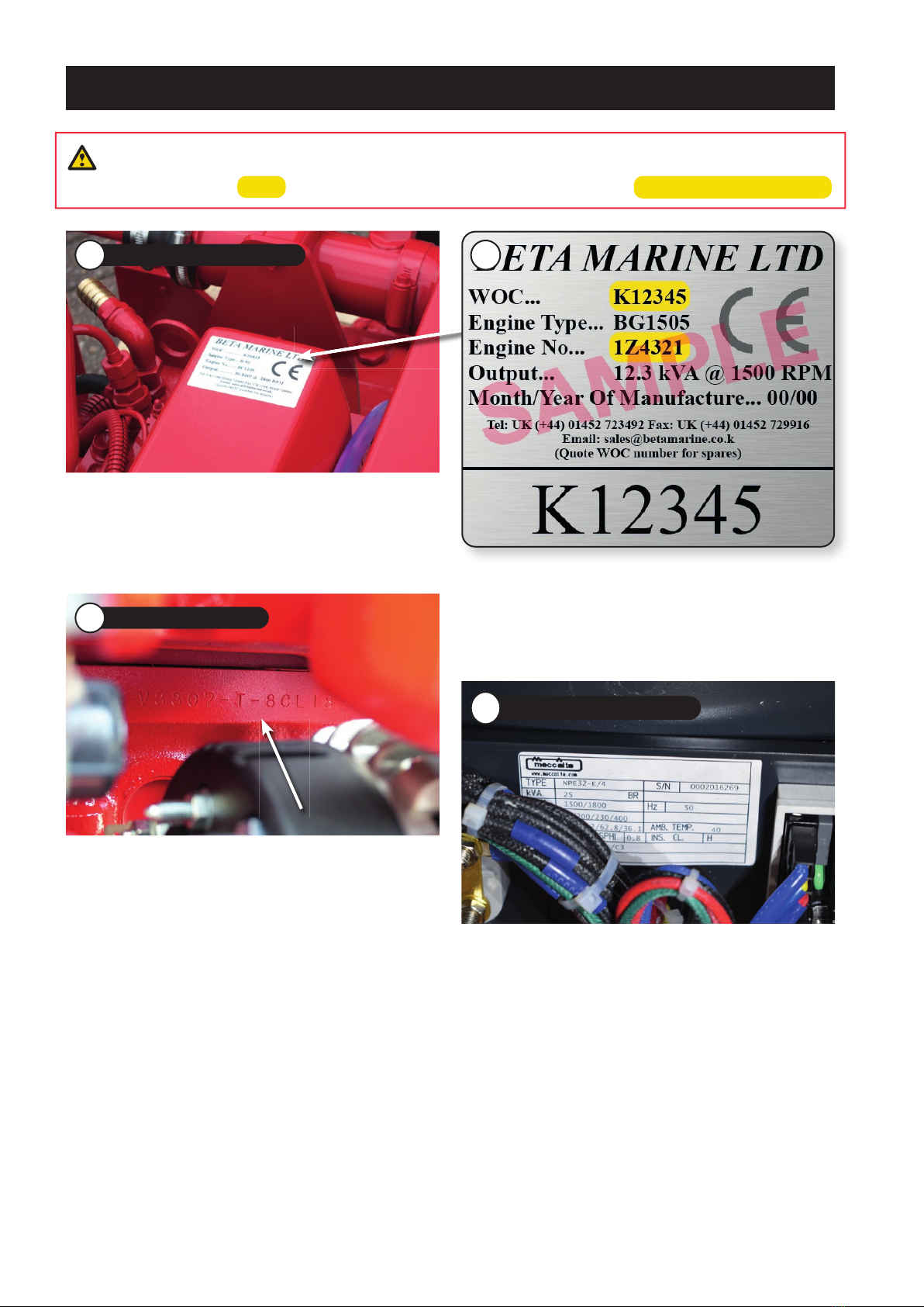
Beta Marine WOC Number
The generating set specification label is located on the
engine rocker cover, it details the WOC number, engine
type, engine serial number and output in kVA.
The engine serial number is additionally stamped on the
engine casing in the locations listed below.
BetaSet-BetaGen 7, 10 & 12
On the crank case above the starter motor on the port
side of the engine when viewed from the AC end.
BetaSet-BetaGen 14 & 21
On the crank case below the fuel injection pump on the
starboard side of the engine when viewed from the AC
end.
BetaSet-BetaGen 26, 33, 40, 49, 40T IIIA & 49T IIIA
On the crankcase behind the fuel filter on the starboard
side of the engine when viewed from the AC end.
BetaSet-BetaGen 4/2, 6/2 & 11/2
On the crank case below the fuel injection pump on the
starboard side of the engine.
4
AC Alternator Serial Number
Additional alternator labels can be found within the
alternator terminal box and on the casing detailing the
alternator type, serial number, kVA, RPM, Frequency in Hz,
Voltage & Phase.
The details on the AC alternator nameplate cover the
range of outputs available for that particular frame size
and may not be specific to the rating of your generating
set.
Please note that the alternator which produces the main
AC output of the generating set is sometimes referred to
as the generator and should not to be confused with the
engine mounted DC starter battery charging alternator.
3
Engine Serial Number
BetaSet-BetaGen 22/2 & 25/2
On the crank case above the starter motor on the port
side of the engine.
2

5
A full inspection of the generating set must be made immediately on delivery to confirm that there is no damage.
If there is any damage then write this clearly on the delivery note and inform your dealer or Beta Marine by the next
working day. It would be appreciated for any claims to be supported by relevant photographs.
INITIAL RECEIPT OF THE GENERATING SET
{
The generating set must be stored in a dry, frost free area and this is best done in its packing case. If storage is to
be more than six months then the engine must be inhibited (contact your dealer or Beta Marine). Failure to inhibit
the engine may result in the formation of rust in the injection system and the engine bores, this could invalidate the
warranty.
GENERATING SET STORAGE
{
Safety Precautions!
WARNING! - ELECTRICITY IS DANGEROUS AND CAN CAUSE DEATH IF THE
GENERATING SET IS NOT CORRECTLY INSTALLED, MAINTAINED AND USED
IMPORTANT!
The decision to connect to the AC electrical output terminals of the generating set is the
responsibility of a qualified/certified electrician who is also responsible for ensuring the safety,
integrity & quality of the electrical circuit being connecting to.
The installation and earthing must be carried out in accordance with the latest edition of the IEE wiring
regulations and we recommend that a ‘Completion Certificate’ is issued by the electrician upon completion.
Standard single phase generating sets leave Beta Marine with one pole earthed (grounded) at the terminal
box (neutral bonding).
The generating set should not be used without the Control Module supplied by Beta Marine Ltd.
Beta Marine recommends the installation of an ELCB (Earth Leakage Circuit Breaker) or an RCD (Residual
Current Device) and a consumer unit with suitably rated MCB’s.
For deck mounted equipment proper waterproof plugs/sockets should be used.
6
C Neutral Bonding
On Single Phase BetaSet and BetaGen the neutral
terminal is bonded to the earth (ground) bolt in
the terminal box. Please refer to image 8. It is the
responsibility of the electrician to determine the
suitability of this arrangement for the installation.
Having the neutral earthed makes the output similar
to domestic UK single phase mains supply. On three
phase generators the generating set leaves our factory
without neutral grounding.
D Drives - Power Take Off Areas
i) Forward End Drive
Generating sets can be supplied with unguarded belt
drives to power the fresh water pump and battery
charging alternator. The installer must ensure that it is
not possible for injury to occur by allowing access to
this area of the engine. The three pulleys run at high
speed and can cause injury if personnel or clothing
come in contact with the belts or pulleys, when the
engine is running. If not originally purchased with
the generating set, forward end alternator guards
are available as an optional extra should they be
additionally required.
8
Neutral Bonding Terminal
A Keep the generating set, and surrounding area
clean, including the area immediately below the
engine.
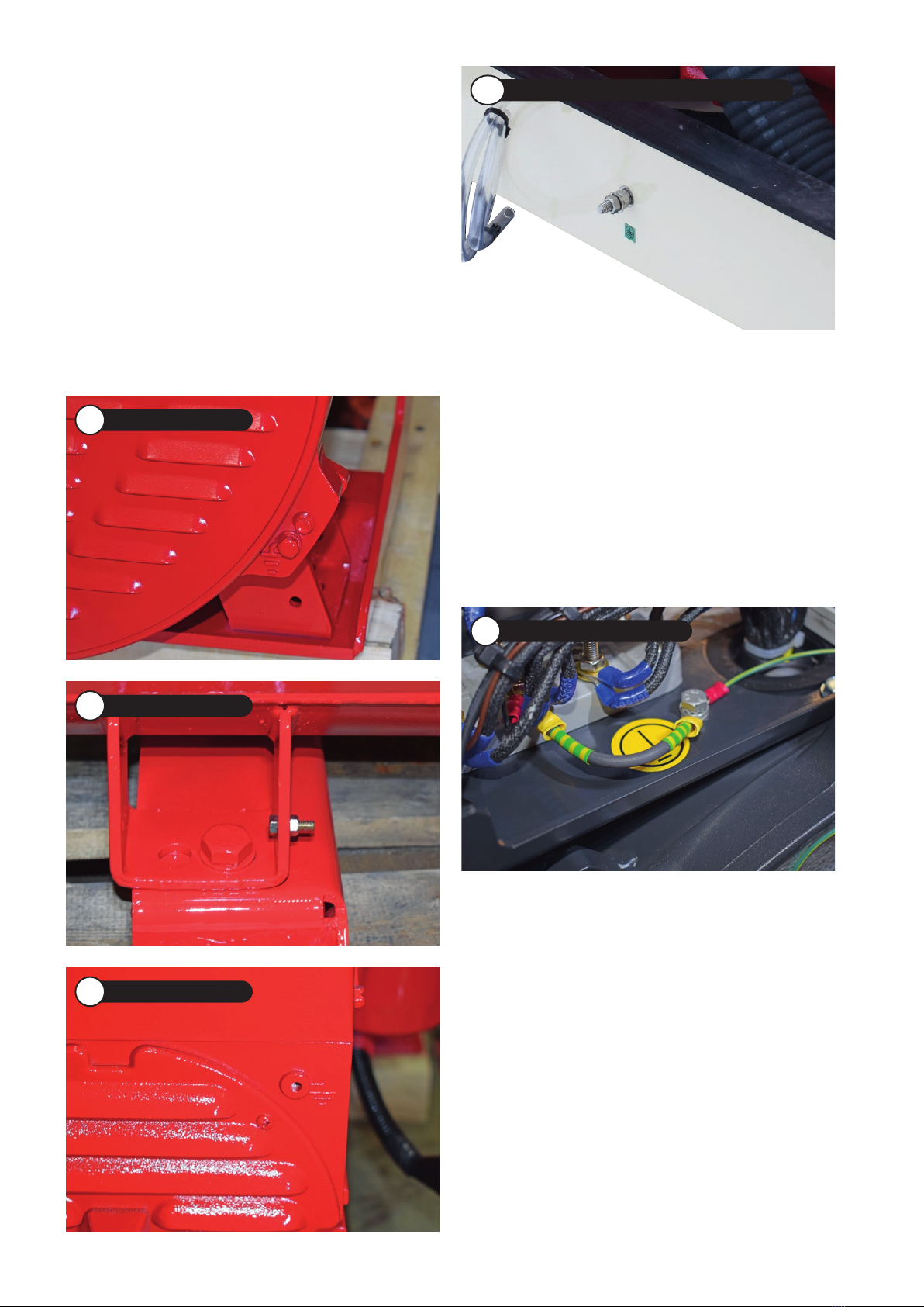
B AC Earthing
The generating set body must be bonded to earth
(grounded). It is the responsibility of the installer to
ensure that proper earthing is provided to comply with
all regulations and legal requirements. The generating
set ‘Earthing Stud’ is located as depicted in images
5, 6 & 7 must be bonded to the vessels hull using
suitably rated earthing cable.
AC Earthing points are located:
5
NPE Earthing Point
7
SF-16 Earthing Point
6
ECO-P Earthing Point
NB:
BetaGen Acoustic Enclosure Earthing Point
Internal earthing is
adding during production

7
ii) Power Take Off Shaft (Engine Mounted Option)
Shaft extensions are available as an option and rotate
at 1500 - 3600 rev/min. If contact is made with this
shaft when the engine is running, injury can occur.
E Exhaust Outlet
Marine diesel generating sets emit exhaust gases
at very high temperatures - around 400°C - 500°C.
Engines are supplied with either wet exhaust outlet
(water injection bend) or dry outlet (dry exhaust stub)
- see option list.
At the outlet next to the heat exchanger/header
tank, the exhaust outlet can become very hot and if
touched, can injure. This must be lagged or avoided
by ensuring adequate guarding. It is the responsibility
of the installer to lag the exhaust system if a dry
system is used. Exhaust gases are harmful if ingested,
the installer must therefore ensure that exhaust lines
are led overboard and that leakage in the vessel does
not occur.
F Fuel
i) Fuel Lines
Diesel engines are equipped with high pressure fuel
injection pumps, if leakages occur, or if pipes fracture,
fuel at a high pressure can harm personnel. Skin must
be thoroughly cleaned in the event of contact with
diesel fuel.
ii) Fuel Supply Connections
Engines are supplied with 8mm compression fittings.
The installer must ensure that when connections are
made, they are clean and free of leaks.
G Oil
The Beta Marine generating set is supplied with a
dipstick for the engine. Ensure the dipstick is returned
and secure after checking, if not oil leaks can cause
infection when touched. All oil must be removed from
the skin to prevent infection.
H Scalding
An engine running under load will have a closed circuit
fresh water temperature of 85° to 95°C. The pressure
cap on the top of the heat exchanger or keel cooled
header tank or radiator cap must not be removed
when the engine is running. It can only be removed
when the engine is stopped and has cooled down.
I Transportation/Lifting
The generating set is supplied with a single lifting
point specifically for the generating set. This is for
lifting the generating set only, not the transport pallet
and any associated accessories or installation items
contained within. Please refer to image 9.
GENERAL DECLARATION
This machinery is not intended to be put into service until
it has been incorporated into or with other machinery. It
is the responsibility of the purchaser/installer/owner, to
ensure that the machinery is properly guarded and that all
necessary health and safety requirements, in accordance
with the laws of the relevant country, are met before it is
put into service.
Signed:
J A Growcoot, C.E.O, Beta Marine Limited.
9
Single Lifting Point

8
Specification Parameters
The Performance Class of the generating set is specified
in International Standard ISO 8528. BetaSet and BetaGen
generating sets perform within the limits of ISO 8528
Class G1.
1.1 Frequency Regulation:
Frequency (Hz) regulation depends upon the loading and
engine governing. Hz is directly related to engine speed.
Steady state – off load can be up to 8% above the full
load Hz. (On many Beta generating sets the off load Hz
will be within 5% above the full load speed although this
cannot be guaranteed especially on the smaller sets). This
is called frequency droop.
• Steady state Hz band is ≤2.5%.
• The rated Hz tolerance band is 3.5%
Accordingly, if the full load speed of the engine is set
such that the output from the generator is produced
at 50Hz (which is 1500 rpm engine speed for a 4-pole
generator) the no load Hz could be as much as 54Hz. At
loads between full load and no load the frequency will lie
between these two figures depending on the magnitude
of the load.
The frequency should be stable, at any steady state load,
within a band width of 2.5% (1.25Hz). So at 100% load,
providing the engine speed is set to produce 50Hz at full
load, the frequency can vary within this 2.5% band. For
example between 49.4 and 50.6Hz.
1.2 Dynamic Behaviour:
• Transient speed increase when 100% load is removed
as a percentage from previous level < 18%.
• Recovery time to new steady state speed band < 10
seconds.
• Transient speed decreases when 100% load is added
as a percentage from previous level < -15%
• Recovery time to new steady state speed band < 10
seconds.
1.3 Waveform:
Waveform is not a significant factor for machines for
domestic or light industrial applications, the reason being
that generator set manufacturers can do little to influence
the waveform because it depends upon the cyclic
irregularity of the generating set (inherent in the design
of the engine and inertia of the set) and the construction
of the generator itself which inherently causes harmonics.
The connected load can also affect the waveform.
No limits are specified for waveform on these generating
sets.
1.4 Voltage Regulation:
‘Steady State’ voltage regulation will be ± 2.5% (± 3.5%
on the smallest machines) of nominal set voltage at
any load up to 100% provided the power factor lies in
the range 0.8 to unity and provided that the engine is
performing in accordance with the parameters detailed
in paragraph 1.1 of this specification. In reality voltage
regulation will, in many cases, be better than this.
Power factors outside the range 0.8 to unity can affect
voltage regulation. Power factor is a function of the
connected load. Resistive loads, such as heaters, are
unity power factor loads where their kVA equals kW. To
obtain the kW rating of any generator set multiply the kVA
rating x 0.8. Outputs to loads having other power factors
may result in specifications outside the limits mentioned
herein.
NB: BetaSet-BetaGen 4/2 and 6/2 are unity factor
machines - kVA = kW.
1.5 Power & Voltage:
• Voltage is that set and measured at the generator
terminals when the machine is connected to a ‘pure’
load whose power factor lies between 0.8 and unity.
(In the UK the nominal voltage is 400v ± 6%, 3-phase,
test voltage for single phase sets can lie between 218v
and 244v, hence the nominal voltage to be used under
steady state conditions will be 231v on full load).
• Voltage performance of Beta Marine generating sets
will be well within the limits specified by ISO 8528
Class G1. When large loads are applied the voltage
will dip and provided such loads are not too large will
recover in a few seconds. In correlation when load is
suddenly removed the voltage will rise with similar
recovery time.

9
1.6 De-rating:
The AC alternators are selected so that they are suitable
for operation in ship engine rooms with an ambient
temperature of up to 45°C. However the diesel engine will
be affected by high temperature and humidity.
Engine de-rating must be applied;
• Should the generating set is installed in an acoustic
housing or for that matter any restricted area where
the fan in the generator is the only means of moving
the air. When Beta Marine acoustic housings are used
output will be de-rated by 10%.
• The conditions of installation differ from the standard
conditions set out in standard ISO 3046, i.e. 100 kPa
barometric pressure, 27°C cooling and combustion
air temperature and 60% relative humidity. Generally
for marine applications only temperature need be
considered when de-rate is usually taken as 2%
(3% for turbocharged engines) for every 5°C (or part
thereof) above 30°C.
1.7 Power Factor:
Power factor is often the cause of much misunderstanding
and is a function of the load NOT the generator. However
generators are designed to cope with loads at various
power factors. Standard machines are designed to cope
with loads having power factor between 0.8 and unity
being rated by the makers at 0.8 power factor. Some
very small machines are designed and rated for unity
power factor loads only. A typical unity power factor load
would be a heater element (resistive load). A system
incorporating a larger electric motor could have a running
power factor nearer to 0.8.
Beta Marine Ltd sell equipment producing ‘POWER’ and
the units of power are kilowatts. To change kVA into kW
multiply by the power factor. As previously stated the
ratings of our generating sets are given in kVA at 0.8
power factor. To obtain the kW rating of the generating set
multiply the kVA x 0.8.
By way of an example for a 30 kVA load: A generating
set offered on our price list at 33 kVA will drive a system
having a rating of 30 kVA where the system power
factor is 0.8. However if the system power factor is unity
(perhaps all heating and lighting) the kW rating of the
system will be 30 x 1 = 30 kW the 33 kVA set will not
power it because its rating will only be 33 x 0.8 = 26.4 kW.
Consequently a set having a rating of 38.5 kW at 0.8
power factor = 30.8 kVA will be required. (38.5 x 0.8 =
30.8 kW).
This is a simple example not a detailed explanation and is
intended for guidance only. The above refers to electrical
kW. The relationship between mechanical kW of the
engine and electrical kW of generator output depends on
the efficiency of the generator and any other driven items.
All of our generating sets are fully load tested against
a unity power factor load, that is at their kW rating. All
sets are also tested to prove that they will provide a 10%
overload in accordance with ISO requirements.
For maximum output, continuous output and typical load
please refer ‘Technical Specification’ pages 12 to 29.

10
For EPA compliance, all sets must be especially quoted for. R: Recreational subject to directive 2013/53/EU (RCD2) | C: Commercial
BetaSet-BetaGen Compliance
Engine Model EU Compliance EU Seagoing Use EU Inland Use
BetaSet-BetaGen 7 Not Required*R: Yes | C: Yes R: Yes | C: Yes
BetaSet-BetaGen 10 EU.2016/1628 Stage V*R: Yes | C: Yes R: Yes | C: Yes
BetaSet-BetaGen 12 EU.2016/1628 Stage V*R: Yes | C: Yes R: Yes | C: Yes
BetaSet-BetaGen 14 EU.2016/1628 Stage V*R: Yes | C: Yes R: Yes | C: Yes
BetaSet-BetaGen 21 EU.2016/1628 Stage V*R: Yes | C: Yes R: Yes | C: Yes
BetaSet-BetaGen 26 97/68/EU Stage IIIA R: Yes | C: Yes R: Yes | C: Yes**
BetaSet-BetaGen 33 97/68/EU Stage IIIA R: Yes | C: Yes R: Yes | C: Yes**
BetaSet-BetaGen 40 Not Available R: Yes | C: Yes R: No | C: No***
BetaSet-BetaGen 40T - IIIA 97/68/EU Stage IIIA R: Yes | C: Yes R: Yes | C: Yes**
BetaSet-BetaGen 49 Not Available R: Yes | C: Yes R: No | C: No***
BetaSet-BetaGen 49T - IIIA 97/68/EU Stage IIIA R: Yes | C: Yes R: Yes | C: Yes**
BetaSet-BetaGen 4/2 Not Required*R: Yes | C: Yes R: Yes | C: Yes
BetaSet-BetaGen 6/2 Not Required*R: Yes | C: Yes R: Yes | C: Yes
BetaSet-BetaGen 11/2 Not Required*R: Yes | C: Yes R: Yes | C: Yes
BetaSet-BetaGen 22/2 Not Available R: Yes | C: Yes R: Yes | C: No
BetaSet-BetaGen 25/2 Not Available R: Yes | C: Yes R: Yes | C: No
* The BetaSet/BetaGen 7, 10, 12, 14, 21, 4/2, 6/2 &
11/2 have engines below 19kW in power and are
currently unregulated for most marine applications.
This means they are suitable for use on seagoing,
recreational and inland waterways craft.
** Stage IIIA engines are only suitable for craft on
European Inland Waterways if the vessel is under 20m
in length or under 100m3displacement, or the craft
is a recreational craft subject to RCD2. Stage IIIA is
equivalent to CCNR2.
For craft 20m and over in length and/or 100m3and over
in displacement, all engines 19kW and over must be Stage
V approved.
NB: All passenger vessels carrying 12 or more passengers
on European inland waterways must have Stage V
approved engines.
(Ref: Directives EU 2016/1628; EU 2016/1629; European
Standard for Inland Navigation Vessels ES-TRIN:2019/1).
*** BetaSet/BetaGen 40 & 49 are only Stage II compliant
and cannot be used on European Inland Waterways
(canals, lakes and rivers including the Rhine).
Important: Local regulations may override these
statements and should be checked.
The above statements are Beta Marines interpretation
of the afore mentioned directives and standards and are
for guidance only. Beta Marine strongly advise that the
customer/installer verifies that the intended engine to
be supplied and installed meets the requirements of the
authority in whose area it is intended that the vessel/craft
will operate in.
Beta Marine accept no liability for local non-compliance
issues, however, do guarantee to supply engines to meet
our current published specification/standard.
NB: The information on this page refers only to
constant speed generator set application.

11

12
4 - Pole Technical Specifications
BetaSet-BetaGen 7
Kubota/Beta Marine 4 - Cycle Base Engine BD905 BG
Cylinders - No. In-line 3
Naturally Aspirated 3
Turbocharged -
After Treatment - Exhaust Gas Recirculation -
Combustion Chamber - E TVCS Indirect Injection 3
Combustion Chamber - E-CDIS Direct Injection -
Fuel Injection Pressure - kgf/cm² (psi) 140 (1991)
Fuel Injection Pump - In-Line 3
Fuel Injection Timing BTDC - °/rpm (°/rpm) 16.5° -18.5°/1500
(16.5° - 18.5°/1800)
Fuel - Diesel Fuel Oil To EN590 Or ASTM D975 3
Engine Governor Mechanical Centrifugal Flyweight
Bore & Stroke - mm (cu.in) 72.0 x 73.6 (2.83 x 2.90)
Compression Ratio 23.0
Displacement - cc (cu in) 898 (54.86)
Engine Maximum Output - HP/rpm (HP/rpm) 10.6/1500 (12.5/1800)
Engine Maximum Output - kW/rpm (kW/rpm) 7.9/1500 (9.3/1800)
Engine Prime Output - HP/rpm (HP/rpm) 9.6/1500 (11.4/1800)
Engine Prime Output - kW/rpm (kW/rpm) 7.2/1500 (8.5/1800)
Starting Aid Glow Plug
Firing Order 1-2-3
Valve Tip Clearance (Cold) - mm (in) 0.145 - 0.185 (0.0057 - 0.0072)
Direction of Rotation - Counter Clockwise (Viewed From The Flywheel) 3
Lubricating Oil System - Forced By Trochoid Pump 3
Lubricating Oil Pressure At Rated RPM - kgf/cm² (psi) 2.0 - 4.5 (28.0 - 64.0)
Lubricating Oil Capacity Of Standard Sump - L (U.S gal) 5.1 (1.3)
Lubricating Oil SAE - Ambient Temperatures Change Requirement, refer to: Page 50
Engine Closed Circuit Coolant Circulation - Pressurised, Forced By Water Pump 3
Engine Closed Circuit Coolant Capacity - Heat Exchanger Engines - L (U.S gal) 7.0 (1.85)
Engine Closed Circuit Coolant - Anti-freeze Mixed 30% > 50% With Water, refer to: Page 46
Electric Start - 12 Volt Grounded Earth 3
Electric Start - 12 Volt Insulated Return & 70 Amp Alternator Opt.
Electric Start - 24 Volt Insulated Return & 55 Amp Alternator Opt.
Min. Recommended Battery Capacity 70Ah 450CCA

13
10 12 14
BD1105 BG BV1505 BG BD1703BG
3 4 3
3 3 3
- - -
- - -
3 3 3
- - -
140 (1991) 140 (1991) 140 (1991)
3 3 3
15.5° - 17.5°/1500 15.5° - 17.5°/1500 17.0° - 19.0°/1500
(16.5° - 18.5°/1800) (16.5° - 18.5°/1800) (17.0° - 19.0°/1800)
3 3 3
All Speed Mechanical All Speed Mechanical All Speed Mechanical
78.0 x 78.4 (3.07 x 3.09) 78.0 x 78.4 (3.07 x 3.09) 87.0 x 92.4 (3.43 x 3.64)
24.0 23.0 23.0
1123 (68.53) 1498 (91.41) 1647 (100.5)
13.6/1500 (16.2/1800) 17.8/1500 (21.4/1800) 20.6/1500 (24.3/1800)
10.1/1500 (12.1/1800) 13.3/1500 (16.0/1800) 15.4/1500 (18.1/1800)
12.3/1500 (14.7/1800) 16.2/1500 (19.5/1800) 18.7/1500 (22.1/1800)
9.2/1500 (11.0/1800) 12.1/1500 (14.6/1800) 14.0/1500 (16.5/1800)
Glow Plug Glow Plug Glow Plug
1-2-3 1-3-4-2 1-2-3
0.145 - 0.185 (0.0057 - 0.0072) 0.145 - 0.185 (0.0057 - 0.0072) 0.18 - 0.22 (0.0071 - 0.0087)
3 3 3
3 3 3
2.0 - 4.5 (28.0 - 64.0) 2.0 - 4.5 (28.0 - 64.0) 3.0 - 4.5 (42.7 - 64.0)
5.1 (1.3) 6.7 (1.8) 7.0 (1.85)
Page 50Page 50 Page 50
3 3 3
7.0 (1.85) 7.0 (1.85) 5.5 (1.45)
Page 46Page 46 Page 46
3 3 3
Opt. Opt. Opt.
Opt. Opt. Opt.
70Ah 450CCA 94Ah 620CCA 94Ah 620CCA

14
BetaSet-BetaGen 7
AC Alternator Mecc Alte, Brushless, Single Bearing With IP 22 Protection 3
Digitally Controlled, Adjustable, Automatic Voltage Regulator 3
4 - Pole (1500rpm) 50Hz 220/230/240v - 1 Phase NPE32-B/4
Maximum AC Output - 50Hz 1 Phase @ 1500 rpm - kVA 6.6
Prime AC Output - 50Hz 1 Phase @ 1500 rpm 0.8PF - kVA 6.0
Typical Maximum Load In Amps Per Phase @ 230v Based On kW Electrical Load 23.0
Approxomate Fuel Consumption @ Prime Power 2.2
4 - Pole (1500rpm) 50Hz 380/400/415v - 3 Phase NPE32-B/4
Maximum AC Output - 50Hz 3 Phase @ 1500 rpm - kVA 6.7
Prime AC Output - 50Hz 3 Phase @ 1500 rpm 0.8PF - kVA 6.0
Typical Maximum Load In Amps Per Phase @ 415v Based On kW Electrical Load 7.0
Approxomate Fuel Consumption @ Prime Power 2.2
4 - Pole (1800rpm) 60Hz 120v - 1 Phase NPE32-B/4
Maximum AC Output - 60Hz 1 Phase @ 1800 rpm - kVA 7.8
Prime AC Output - 60Hz 1 Phase @ 1800 rpm 0.8PF - kVA 7.1
Typical Maximum Load In Amps Per Phase @ 120v Based On kW Electrical Load 48.0
Approxomate Fuel Consumption @ Prime Power 2.3
4 - Pole (1800rpm) 60Hz 208v - 3 Phase NPE32-B/4
Maximum AC Output - 60Hz 3 Phase @ 1800 rpm - kVA 8.6
Prime AC Output - 60Hz 3 Phase @ 1800 rpm 0.8PF - kVA 7.8
Typical Maximum Load In Amps Per Phase @ 208v Based On kW Electrical Load 17.0
Approxomate Fuel Consumption @ Prime Power 2.2
Approximate Nett Dry Weight 7
BetaSet - Kg (lbs) 237
BetaGen - Kg (lbs) 290

15
10 12 14
3 3 3
3 3 3
NPE32-D/4 NPE32-E/4 NPE32-E/4
9.7 12.3 14.0
8.8 11.2 12.7
31.0 39.0 44.0
2.7 3.6 3.6
NPE32-B/4 NPE32-D/4 NPE32-D/4
10.1 13.0 14.5
9.2 11.8 13.2
10.0 13.0 15.0
2.9 3.7 3.7
NPE32-D/4 NPE32-E/4 NPE32-E/4
9.7 15.5 17.6
8.8 14.1 16.0
64.6 94.0 107.0
3.1 4.3 4.6
NPE32-B/4 NPE32-D/4 NPE32-E/4
11.5 16.1 18.2
10.5 14.6 16.5
25.0 33.0 37.0
3.1 4.4 4.6
10 12 14
245 263 390
300 345 498

16
BetaSet-BetaGen 21
Kubota/Beta Marine 4 - Cycle Base Engine BV2203 BG
Cylinders - No. In-line 4
Naturally Aspirated 3
Turbocharged -
After Treatment - Exhaust Gas Recirculation -
Combustion Chamber - E TVCS Indirect Injection 3
Combustion Chamber - E-CDIS Direct Injection -
Fuel Injection Pressure - kgf/cm² (psi) 140 (1991)
Fuel Injection Pump - In-Line 3
Fuel Injection Timing BTDC - °/rpm (°/rpm) 17.0° - 19.0°/1500
(17.0° - 19.0°/1800)
Fuel - Diesel Fuel Oil To EN590 Or ASTM D975 3
Engine Governor All Speed Mechanical
Bore & Stroke - mm (cu.in) 87.0 x 92.4 (3.43 x 3.64)
Compression Ratio 22.0
Displacement - cc (cu in) 2197 (111.31)
Engine Maximum Output - HP/rpm (HP/rpm) 27.6/1500 (32.4/1800)
Engine Maximum Output - kW/rpm (kW/rpm) 20.6/1500 (24.2/1800)
Engine Prime Output - HP/rpm (HP/rpm) 25.2/1500 (29.5/1800)
Engine Prime Output - kW/rpm (kW/rpm) 18.8/1500 (22.0/1800)
Starting Aid Glow Plug
Firing Order 1-3-4-2
Valve Tip Clearance (Cold) - mm (in) 0.18 - 0.22 (0.0071 - 0.0087)
Direction of Rotation - Counter Clockwise (Viewed From The Flywheel) 3
Lubricating Oil System - Forced By Trochoid Pump 3
Lubricating Oil Pressure At Rated RPM - kgf/cm² (psi) 3.0 - 4.5 (42.7 - 64.0)
Lubricating Oil Capacity Of Standard Sump - L (U.S gal) 7.6 (2.0)
Lubricating Oil SAE - Ambient Temperatures Change Requirement, refer to: Page 50
Engine Closed Circuit Coolant Circulation - Pressurised, Forced By Water Pump 3
Engine Closed Circuit Coolant Capacity - Heat Exchanger Engines - L (U.S gal) 7.4 (1.96)
Engine Closed Circuit Coolant - Anti-freeze Mixed 30% > 50% With Water, refer to: Page 46
Electric Start - 12 Volt Grounded Earth 3
Electric Start - 12 Volt Insulated Return & 70 Amp Alternator Opt.
Electric Start - 24 Volt Insulated Return & 55 Amp Alternator Opt.
Min. Recommended Battery Capacity 94Ah 620CCA

17
26 33 40
BV3300 BG BV3300 BG BV3800
4 4 4
3 3 3
- - -
- - -
3 3 3
- - -
140 (1991) 140 (1991) 1st 190 (2702), 2nd 240 (3414)
3 3 3
10.0°/1500 10.0°/1500 13.0°/1500
(11.0°/1800) (11.0°/1800) (13.0°/1800)
3 3 3
All Speed Mechanical All Speed Mechanical Mechanical Centrifugal Flyweight
98.0 x 110.0 (3.86 x 4.33) 98.0 x 110.0 (3.86 x 4.33) 100.0 x 120.00 (3.94 x 4.72)
22.6 22.6 20.0
1498 (202.5) 3318 (202.5) 3769 (230.0)
41.8/1500 (51.3/1800) 41.8/1500 (51.3/1800) 53.6/1500 (62.8/1800)
31.2/1500 (38.2/1800) 31.2/1500 (38.2/1800) 40.0/1500 (46.9/1800)
38.0/1500 (46.6/1800) 38.0/1500 (46.6/1800) 48.8/1500 (57.2/1800)
28.4/1500 (34.8/1800) 28.4/1500 (34.8/1800) 36.4/1500 (42.7/1800)
Glow Plug Glow Plug Intake Air Heater (When Required)
1-3-4-2 1-3-4-2 1-3-4-2
0.23 - 0.27 (0.0091 - 0.0106) 0.23 - 0.27 (0.0091 - 0.0106) 0.23 - 0.27 (0.0091 - 0.0106)
3 3 3
3 3 3
2.0 - 4.0 (28.0 - 56.0) 2.0 - 4.0 (28.0 - 56.0) 2.0 - 4.0 (28.0 - 57.0)
13.2 (3.49) 13.2 (3.49) 13.2 (3.49)
Page 50Page 50Page 50
3 3 3
12.5 (3.30) 12.5 (3.30) 10.2 (2.70)
Page 46Page 46Page 46
3 7 7
Opt. Opt. 3
Opt. Opt. Opt.
108Ah 1050CCA 108Ah 1050CCA 108Ah 1050CCA

18
BetaSet-BetaGen 21
AC Alternator Mecc Alte, Brushless, Single Bearing With IP 22 Protection 3
Digitally Controlled, Adjustable, Automatic Voltage Regulator 3
4 - Pole (1500rpm) 50Hz 220/230/240v - 1 Phase ECP32-2S/4
Maximum AC Output - 50Hz 1 Phase @ 1500 rpm - kVA 19.4
Prime AC Output - 50Hz 1 Phase @ 1500 rpm 0.8PF - kVA 17.6
Typical Maximum Load In Amps Per Phase @ 230v Based On kW Electrical Load 61.2
Approxomate Fuel Consumption @ Prime Power 4.7
4 - Pole (1500rpm) 50Hz 380/400/415v - 3 Phase NPE32-E/4
Maximum AC Output - 50Hz 3 Phase @ 1500 rpm - kVA 20.0
Prime AC Output - 50Hz 3 Phase @ 1500 rpm 0.8PF - kVA 18.2
Typical Maximum Load In Amps Per Phase @ 415v Based On kW Electrical Load 20.2
Approxomate Fuel Consumption @ Prime Power 4.8
4 - Pole (1800rpm) 60Hz 120v - 1 Phase ECP32-2S/4
Maximum AC Output - 60Hz 1 Phase @ 1800 rpm - kVA 24.8
Prime AC Output - 60Hz 1 Phase @ 1800 rpm 0.8PF - kVA 22.5
Typical Maximum Load In Amps Per Phase @ 120v Based On kW Electrical Load 150.0
Approxomate Fuel Consumption @ Prime Power 5.8
4 - Pole (1800rpm) 60Hz 208v - 3 Phase ECP28-2L/4
Maximum AC Output - 60Hz 3 Phase @ 1800 rpm - kVA 24.8
Prime AC Output - 60Hz 3 Phase @ 1800 rpm 0.8PF - kVA 22.5
Typical Maximum Load In Amps Per Phase @ 208v Based On kW Electrical Load 51.0
Approxomate Fuel Consumption @ Prime Power 6.0
Approximate Nett Dry Weight 21
BetaSet - Kg (lbs) 454
BetaGen - Kg (lbs) 580
This manual suits for next models
31
Table of contents
Popular Portable Generator manuals by other brands

Power Max
Power Max XP10000E owner's manual

Load UP
Load UP 75020 instruction manual

Far Tools
Far Tools GGC 3300 manual

Expert Power
Expert Power OMEGA 1500 owner's manual

EcoPower
EcoPower CIPR-15Z NG/LP Installation and user instructions

FRONIUS
FRONIUS TransArc 150 Leybold Operating instructions/spare parts list


