6OPM-115
REV A
INTRODUCTION
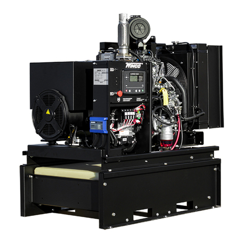
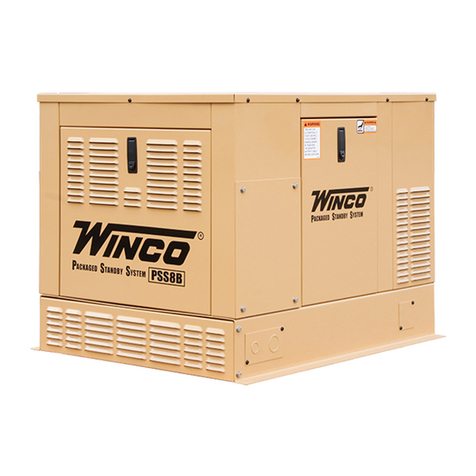
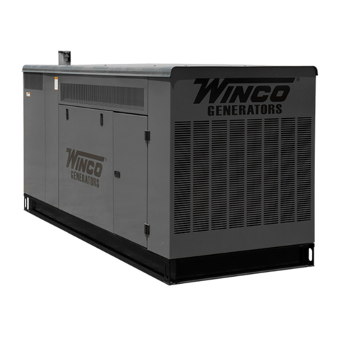
PRODUCT DESCRIPTION
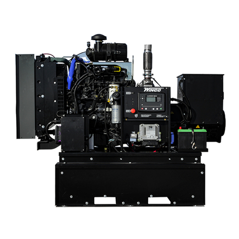
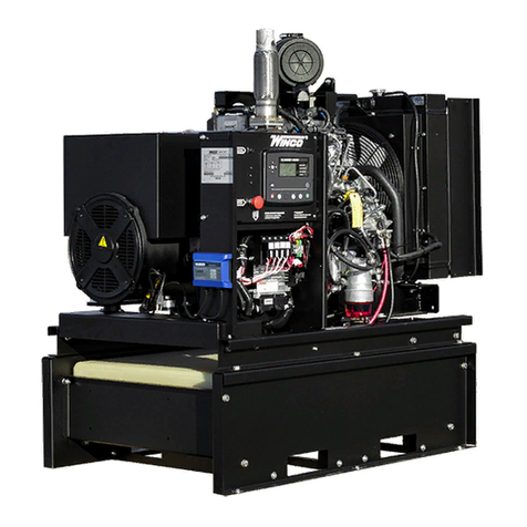
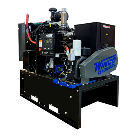
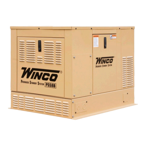
This engine-generator set is designed for unattended remote start
operation. It can be operated as part of a fully automatic standby power
system or independently as a local start unit in a prime power system.
The engine-generator set is fully tested at the factory prior to shipment
to insure proper operation of each individual component as well as the
total system’s performance and reliability.
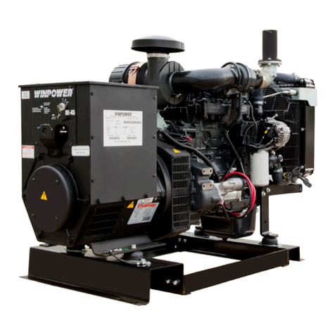
The engine generator set consists of a multi-cylinder, liquid cooled
enginenominallyoperatingat1800rpm.Thegeneratorfrequency
regulationismaintainedbytheenginegovernortowithin+/-1.5Hz
(cps),fromnoloadtoratedloadforstandardmechanicalgovernors
andtowithin+/-.5Hzorbetterforunitsequippedwithanelectronic
governor.Thegeneratorisasinglebearing,directdrive,rotatingeld
design.Thegeneratorisconnectedtotheengineywheelviaexible
drive disks. Generator set is skid mounted with isolation mounts
between the engine and base on all units.
A customer supplied 12 Volt battery is required to complete the
installation, the DX250-350 are 24 Volt systems. Battery requirements
are listed later under the battery installation section.
Unit Orientation Note: All references used in this manual for unit
familiarization,accessandcomponentlocationsontheGeneratorSet
areorientedfromaTOP(plan)VIEWwithengineattheFRONTand
generator to the REAR.
WINPOWER uses a common junction box for all customer control and
powerconnections(bothACoutputandDCcontrol).Thecommon
electrical junction box is always on the left side at the generator end of
the machine.
The engine is controlled and Generator Set operation is monitored for
safe operation by a programmable microprocessor based electronic
EngineControlModule(ECM)withanLCDdigitaldisplay.The
generator set ECM control is mounted on a vertical pedestal on the
right side of the generator. The ECM is programmed with a cycle
crankingsequence-3cyclesof15secondson/15secondsoff,and
5 minute cool-down delay. The cool-down delay can be changed in
theeldfrom0to30minutesbyyourinstaller.Otherfeatures,timing
StamfordNewageModel#UCI274H(12lead)
Voltage Regulator SX460
RotorResistance 1.82ohms
StatorResistance 0.0155ohms/phase
Excitor Stator Resistance 20.0 ohms
ExcitorRotorResistance 0.091ohms/phase
StamfordNewageModel#HCI434D(12lead)
Voltage Regulator MX341
Rotor Resistance 1.05 ohms
StatorResistance 0.00124ohms/phase
ExcitorStatorResistance 18.0ohms
ExcitorRotorResistance 0.068ohms/phase
cycles, set points, and signal output capabilities are possible. Consult
factory for procedure and passwords.
NOTICE:
These units will automatically transfer if a power outage occurs while
running in exercise mode.
GENERATOR SET
Every WINCO generator set has its own unique identity data plate.
Thisdataplateidentiesthecompleteunitmodelnumber,thesystem
serial number, and has links to the individual components that form the
generator set in our factory records. Several of the major components
also have their own individual data plates providing additional
information to document build data for warranty and replacement parts.
ENGINE
Refer to the engine operators manual for more detailed operation and
maintenance information.
CAUTION: EQUIPMENT DAMAGE:
Be sure to check the engine oil level frequently as specied in the
engine manual.
The engine manufacturer has established an excellent worldwide
engineserviceorganization;engineserviceisavailablefromanearby
authorizeddealerordistributor.GototheWINCOwebsiteforalistof
enginedealers(http://wincogen.com/Engine_Support)orcontactthe
WINCO Service Department.
The rated power of each engine-generator is limited by the
temperature,altitude,andallotherambientconditionsspeciedby
the engine manufacturer. Engine power may decrease 3½% for each
1000 feet above sea level, and will decrease an additional 1% for each
10 degrees Fahrenheit above 60° Fahrenheit. Units should not be
operated in ambient temperature greater than 125° Fahrenheit.
GENERATOR
WINCOgeneratorsetsusebrushless,AVR(Auto-VoltageRegulator)
controlled broad-range generator ends. The generator converts
rotational mechanical energy into electrical energy. These WINCO units
are equipped with generators manufactured by Cummins Generator
Technology. Each generator ‘end’ has its own data tag. A unique serial
number is on the data plate.
MODEL NUMBER STRUCTURE
The WINPOWER alpha-numerical numbering consists of a base model
designation, followed by an options section, separated by a dash mark.
The base component of the model numbering system identifies an
engine type, engine starting method, fuel type, kilowatt rating, engine
manufacturer, and number of generator poles. Following the separation
dash mark is the voltage connection and optional installed equipment.
Optionsincludefeatureslike,weatherenclosures(housing),base
mountedfueltanksizes,andtraileroptions.
Please note that some features or packages, such as NFPA level I
& II, do not have an indication place in this numbering system. They
areissuedandbuiltwithanM-Spec(i.e.M-10372)numberwhichcan
