Beta Prusa DualX User manual

Assembly Instructions Beta Prusa DualX 13/05/14
Assembly Instructions
Beta Prusa DualX
3D Printer
Version 2.6
Date 13/05/14
Pa e 1 / 72

Assembly Instructions Beta Prusa DualX 13/05/14
General data about the assembly instructions for an incomplete machine
according to appendix VI of the EG machinery directi e 2006/42/EG
Manufacturer:
Wen er & Krautwasser GbR - 2PrintBeta
Reisstrasse 5
78467 Konstanz
Description of the machine:
Identification: Beta Prusa 3D printer
Type: DualX with two printheads
Year: 2014
Conditions that must be met for the incomplete machine so that it can properly, and
without compromisin the safety and health of peoples, be assembled with other
parts to form a complete machine:
Condition 1: Let an expert check the electrical connections of the machine.
Information over the undersi ned:
Name: Dominik Wenger
Function: Shareholder Wenger & Krautwasser GbR
11. 4.2 14
_________________________________________
Date, Signature
This work is licensed under a Creative Commons Attribution-NonCommercial 3.0 Germany License.
Pa e 2/ 72

Assembly Instructions Beta Prusa DualX 13/05/14
Con ratulations on purchasin a Beta Prusa 3D Printer!
Please read the followin assembly instructions carefully and keep the document on a safe
place. Please follow carefully all instructions and lookout for the warnin symbols.
Table of Contents
SAFETY INSTRUCTIONS....................................................................................................................................4
ASSEMBLY OF THE FRAME..............................................................................................................................5
STEP 1.1
.................................................................................................................................................................
6
STEP 1.2
.................................................................................................................................................................
7
STEP 1.3
.................................................................................................................................................................
9
STEP 1.4
...............................................................................................................................................................
1
STEP 1.5
...............................................................................................................................................................
11
STEP 1.6
...............................................................................................................................................................
12
STEP 1.7
...............................................................................................................................................................
13
STEP 1.8
...............................................................................................................................................................
14
STEP 1.9
...............................................................................................................................................................
17
ASSEMBLY OF THE AXES................................................................................................................................18
STEP 2.1
...............................................................................................................................................................
19
STEP 2.2
...............................................................................................................................................................
21
STEP 2.3
...............................................................................................................................................................
24
STEP 2.4
...............................................................................................................................................................
26
STEP 2.5
...............................................................................................................................................................
28
STEP 2.6
...............................................................................................................................................................
3
STEP 2.7
...............................................................................................................................................................
32
ASSEMBLY OF THE EXTRUDERS..................................................................................................................35
STEP 3.1
...............................................................................................................................................................
36
STEP 3.2
...............................................................................................................................................................
38
STEP 3.3
...............................................................................................................................................................
39
STEP 3.4
...............................................................................................................................................................
41
ASSEMBLY OF PRINT BED AND EXTRAS....................................................................................................42
STEP 4.1
...............................................................................................................................................................
43
STEP 4.2
...............................................................................................................................................................
44
STEP 4.3
...............................................................................................................................................................
45
ASSEMBLY OF THE ELECTRONICS..............................................................................................................48
STEP 5.1
...............................................................................................................................................................
49
STEP 5.2
...............................................................................................................................................................
52
STEP 5.3
...............................................................................................................................................................
54
STEP 5.4 (OPTIONAL)
...........................................................................................................................................
69
STEP 5.5 (OPTIONAL)
...........................................................................................................................................
71
Pa e 3/ 72

Assembly Instructions Beta Prusa DualX 13/05/14
Safety Instructions
Only assemble a Beta Prusa 3D printer accordin to the assembly instructions written here.
Please take notice of the followin Symbols and Notices. They are structured into dan er
levels accordin to ISO 3864-2.
DANGER
Refers to an imminent Danger.
If the information is not followed, it can result in death or serious injury
(in alidity).
Indicates a possible dangerous situation.
If the information is not followed, it can result in death or serious injury
(in alidity).
ATTENTION
Indicates a potentially dangerous situation.
If the information is not followed, damage to property or light to
medium personal injuries are possible.
NOTICE
Indicates general notes, useful operator tips and operating
recommendations which do not affect the safety and health of
personnel.
Pa e 4/ 72
WARNING

Assembly Instructions Beta Prusa DualX 13/05/14
Chapter I
Assembly of the Frame
Pa e 5 / 72
Assembly Instructions Beta Prusa DualX 13/05/14
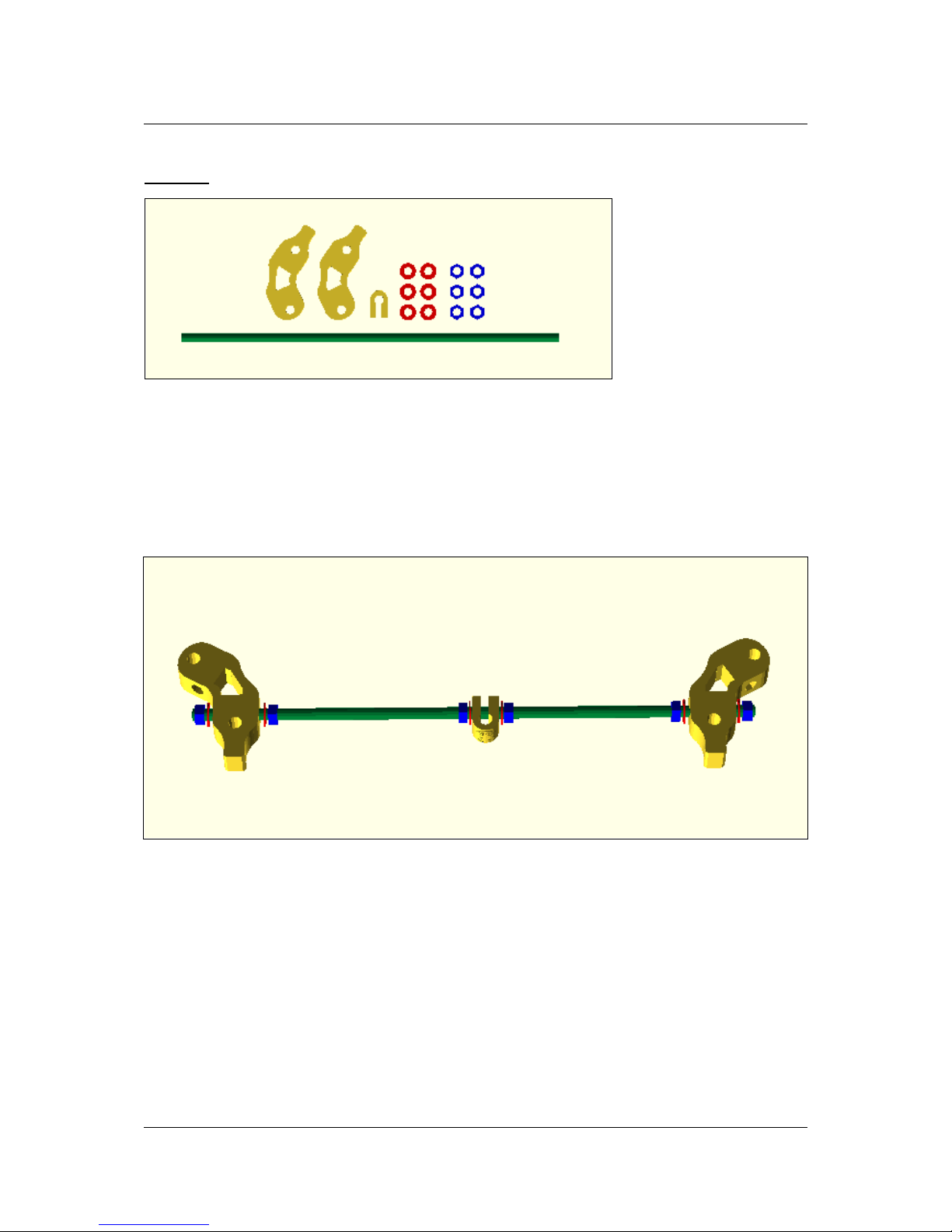
Step 1.1
Needed parts for step 1.1
The followin parts are needed for this step:
2x Frame vertex with foot
1x Bar clamp
6x Washer M8
6x Nut M8
1x Threaded rod M8 x 370 mm
Assembly Step 1.1
Assemble the bar clamp between two frame vertices like its shown in the picture above.
Don't completely fasten the nuts yet.
Pa e 6/ 72
Assembly Instructions Beta Prusa DualX 13/05/14
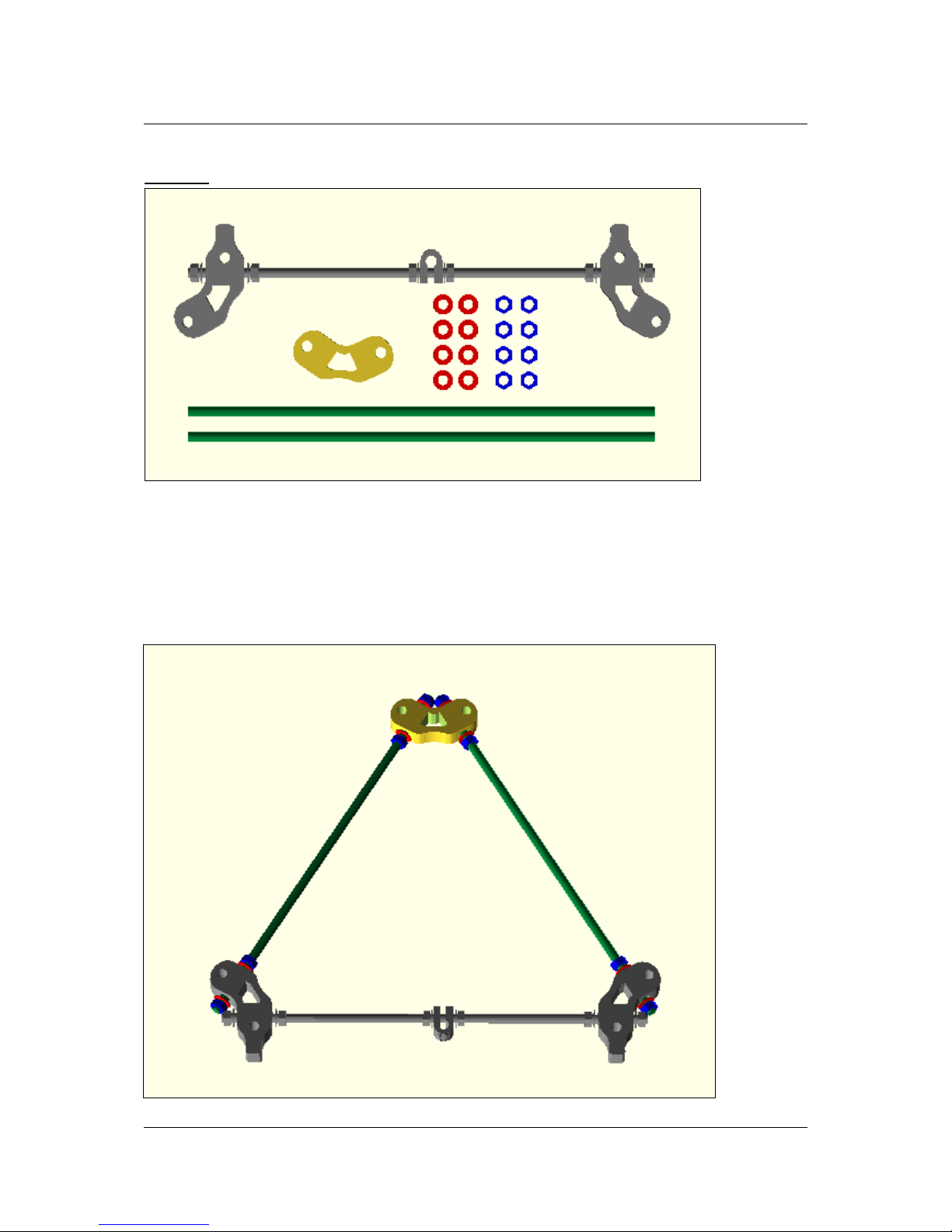
Step 1.2
Needed parts for step 1.2
The followin parts are needed for this step:
1x Pre-assembled part from step 1.1
1x Frame vertex without foot
8x Washer M8
8x Nut M8
2x Threaded rod M8 x 370 mm
Assembly Step 1.2
Pa e 7/ 72
Assembly Instructions Beta Prusa DualX 13/05/14
Connect the part from step 1.1 with the frame vertex and the rods to a trian le.
Make sure that all sides of the trian le are exactly the same len th. The distance between
the outer ed es of the plastic parts should be 291 mm.
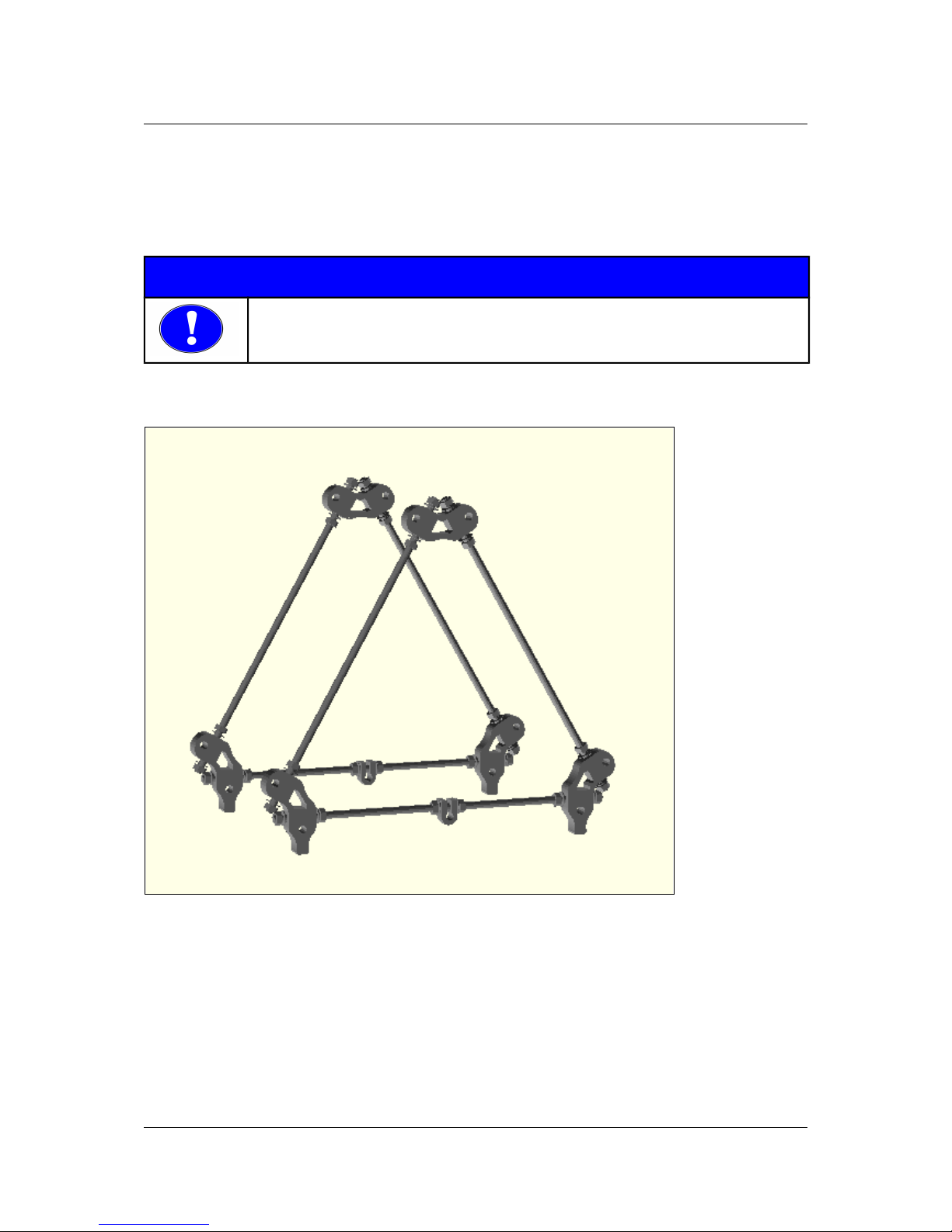
Repeat the previous two steps and build a second trian le.
NOTICE
Make sure all sides of both triangles are exactly the same length.
Now fasten all nuts on the frame vertices.
Assembly of step 1.2 repeated
Pa e 8/ 72

Assembly Instructions Beta Prusa DualX 13/05/14
Step 1.3
Needed parts for step 1.3
The followin parts are needed for this step:
4x Washer M8
4x Nut M8
1x Threaded rod M8 x 294 mm
Assembly Step 1.3
Position the nuts and washer on the threaded rod as shown in the picture above.
Pa e 9/ 72

Assembly Instructions Beta Prusa DualX 13/05/14
Step 1.4
Needed parts for step 1.4
The followin parts are needed for this step:
1x Belt uide
2x Bar clamp
10x Washer M8
2x Bi Washer M8
8x Nut M8
1x Bearin 608ZZ
1x Threaded rod M8 x 294 mm
Bearing 608zz in belt guide
Press the 608ZZ bearin into the belt uide until it's in the middle of the uide.
Assembly step 1.4
Position the parts on the threaded rod as shown in the picture above.
Pa e 10/ 72
Table of contents


