BETCO Fastdraw Pro 92682-00 User manual

Section Page
1. Parts Schematic/List................................. 2 - 3
2. System Description.........................................4
3. Pre-Installation Requirements.........................4
4. Tools Required for Installation ........................4
5. System Installation .........................................5
6. Product Installation.........................................6
7. Drip Tray Installation.......................................6
8. Operation ........................................................6
9. Accessing Internal Dispenser Parts.................6
10. User Guidelines...............................................6
11. Troubleshooting Guide....................................7
92682-00 Fastdraw Pro Action Gap
92698-00 Fastdraw Pro Airgap
Technical Manual
WARNINGS
All installations must conform to local
plumbing codes and use approved backflow
prevention devices. A pressure indicating
tee is to be installed with existing faucets
according to local plumbing codes in the state
of Wisconsin and any other state that requires
the use of a pressure indicting tee.
ALWAYS WEAR PROTECTIVE CLOTHING AND
EYEWEAR WHEN WORKING WITH CHEMICAL
PRODUCTS.

2
1. PARTS SCHEMATIC

3
PARTS LIST
Number Description Qty. Part Number
1 Water Valve Assembly 1 92699-00
2 Selector Push Button Assembly 1 92700-00
3 Bottle Fill Outlet Tube (Action Gap) 1 98318-00
Bottle Fill Outlet Tube (Air Gap) 1 98301-00
Bottle Fill Priming Tube (Air Gap) (Not shown) 1 98302-00
4 Bottle Fill Action Gap Eductor/Selector Assembly Complete 1 92701-00
Bottle Fill Air Gap Eductor/Selector Assembly Complete 1 92702-00
5 Bucket Fill Action Gap Eductor/Selector Assembly Complete 1 92703-00
Bucket Fill Air Gap Eductor/Selector Assembly Complete 1 92704-00
6 Drip Tray 1 92705-00
7 Bucket Fill Outlet Tube (Action Gap) 1 98317-00
Bucket Fill Outlet Tube (Air Gap) 1 98300-00
8 Water Inlet Hose 1 98542-00
9 One Hand Fill Bracket Assembly 1 92706-00
10 Diaphragm 1 92707-00
11 Valve Diaphragm Repair Kit 1 98324-00
12 Bucket Fill Air Gap Eductor 1 98396-00
13 Action Gap Back Flow Preventer 2 98312-00
14 Bucket Fill Action Gap Eductor 1 98313-00
15 Bucket Fill Selector Valve 1 92708-00
16 Bottle Fill Selector Valve 1 92709-00
17 Bottle Fill Action Gap Eductor 1 98314-00
18 Bottle Fill Air Gap Eductor 1 98299-00
19 Keys (Not Shown) 1 98337-00
20 ¼” I.D. Vinyl Tubing (Not Shown) 1 98351-00
21 Docking Caps (Not Shown) 4 92502-00
22 Wall Mounting Kit (4 Wall Anchors & Screws) (Not Shown) 1 98543-00

4
2. SYSTEM DESCRIPTION
WATER SUPPLY REQUIREMENTS
Minimum Maximum
Water Pressure 25 psi (1.72 bar) 70 psi (4.83 bar)
Water Temperature - 100ºF (37.78ºC)
** Recommended water pressure is between 25 psi (1.72 bar) and 70 psi. (4.83 bar).
If pressure exceeds 70 psi, it is recommended that a 40 psi pressure regulator (part
#98394-00) is used.
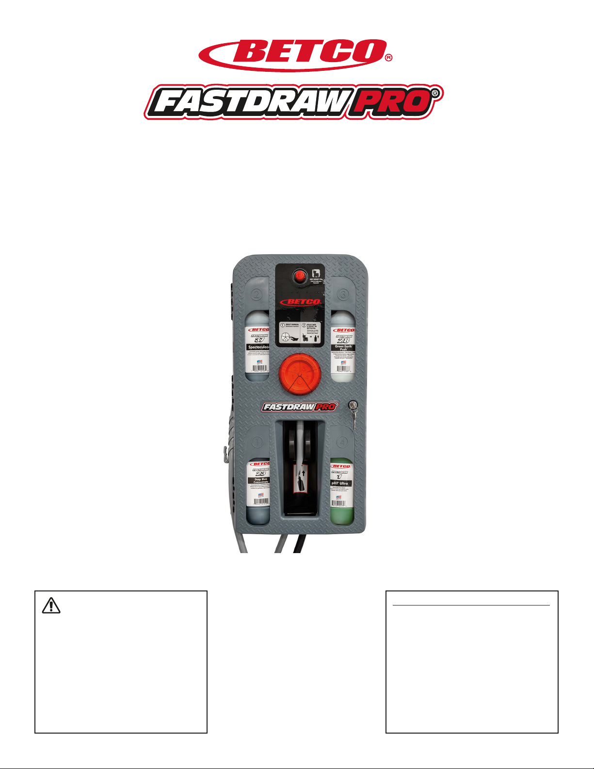
FASTDRAW PRO®is the most robust and convenient four (4) product system in the industry; designed innovative features that help users perform
their jobs faster and better. The following is just a short list of features and benefits in this system:
• Solid durable construction – Dispenser will handle the rigors of heavy wear-n-tear.
• Three-point locking – Secure locking system that prevents theft and pilferage.
• Mounting options – The dispenser can be mounted in a corner or a flat wall.
• Metering tips – No metering tips are needed. Each Betco refill comes with pre metered inserts.
• Bottle or Bucket Fill – Each bay in this dispenser can fill bottles (1 GPM), mop buckets (4 GPM), or automatic scrubbers (4 GPM)
• One-Hand bottle fill – Filling quart bottles has never been easier; simply slide the quart bottle on the tube and push forward.
• Backflow prevention – Dispenser comes in either Action Gap or Airgap which are ASSE and IAPMO approved.
• Viewing window – Each chemical bay has one large window to easily identify the type of product as well as how much of each product is
remaining.
3. PRE-INSTALLATION REQUIREMENTS
WARNING: INSTALLATION MUST MEET ALL APPLICABLE PLUMBING CODES AND REGULATIONS ESTABLISHED BY NATIONAL, CITY, COUNTY,
PARISH, PROVINCIAL OR OTHER AGENCIES. IT IS POSSIBLE THAT PLUMBING CODES AND REGULATIONS REQUIRE THAT A CERTIFIED
INSTALLATION CONTRACTOR OR ENGINEER PERFORM THE PLUMBING INSTALLATION.
• Thoroughly read the entire technical manual prior to the installation of the dispenser.
• Know what products are required for use in maintaining the facility.
• Make sure all components outlined in the parts schematic are in the carton.
• Use water supply lines from tap water outlets with a minimum of 25 PSI, not to exceed 70 PSI, and water temperature must not exceed 100°
Fahrenheit.
• Make sure the mounting surface can hold a 40lb. vertical load.
• If flat wall mounting near a corner, allow 12” to the left of the dispenser to open the door properly.
• Install the unit close to a floor drain or sink whenever possible.
• As with all chemical management systems, place it in an area that can be secured from unauthorized personnel. FASTDRAW PRO®has one locking
door to prevent tampering or theft.
4. TOOLS REQUIRED FOR INSTALLATION
• Hammer
• Tape Measure
• Drill with 9/32” drill bit
• Medium Phillips head screwdriver
• Pencil
• 2 ft level

5
5. SYSTEM INSTALLATION
FLAT WALL INSTRUCTIONS
• Use cardboard mounting template
for flat wall and mark 4 drill holes.
• Use level to make sure cardboard
board mounting template is level.
• Drill holes using the 9/32” drill bit
• Insert the anchors into the drilled
holes and tap them into the wall
until the anchors are flush to the
wall.
• Place the top 2 screws into the
anchors and tighten about halfway.
• Hang the dispenser and tighten
fully. Thread in remaining bottom
screws into wall anchors and tighten
fully.
• Connect the black inlet water hose
to the water supply. Turn on the
water to check for leaks. If leaks are
present, tighten the hose connection
accordingly. Do not over tighten.
CORNER MOUNT INSTRUCTIONS
• Unlock and open the dispenser
door and hold the dispenser in the
location to be mounted
• Using the level, check to make sure
the dispenser is level.
• Mark All 4 holes to be mounted.
(These holes are located in the
corner of the unit.)
• Drill holes using the 9/32” drill bit
• Insert the anchors into the drilled
holes and tap them into the wall
until the anchors are flush with the
wall.
• Hold dispenser up to anchors and
loosely screw in the top two screws.
• Screw in the bottom two screws
into the anchors and tighten.
• Finish by tightening the top two
screws.
• Connect the black inlet water hose
to the water supply. Turn on the
water to check for leaks. If leaks are
present, tighten the hose connection
accordingly. Do not over tighten.

6
6. PRODUCT INSTALLATION
• Open the door of the dispenser. Determine which product you wish to use in each dispenser bay. Find the supplied docking cap hanging in each
bay. Place the product in the bay and screw the cap onto the bottle. (DO NOT OVERTIGHTEN) Continue installing the rest of the products in the
remaining bays.
• Prime each product by depressing each selector position, one at a time, and press the bottle fill button. Once the bottle fill chemical line, for that
compartment, is primed, switch to the bucket fill and prime the tubing. Once finished, complete this step for each compartment.
• Close and lock the door.
7. DRIP TRAY INSTALLATION
• (Only use if mounting above a sink or other water collection area.) The Fastdraw Pro drip tray will prevent any chemical buildup from accidental
spill/misuse of dispenser.
• Drill a hole in tube mounting post using 1/8” drill bit. Slide tubing onto mounting post. Place back into dispenser. Place other end of tube in or
above drain or other water collection area.
8. OPERATION
Bottle fill
• Press the selector button to the desired product.
• Slide the quart bottle onto the hose and press the bottle on the button to activate the dispenser.
Bucket Fill
• Press the selector button to the desired product.
• Place the outlet hose into a mop bucket or automatic scrubber and press the red button near the top of the dispenser to start filling. The button can
be locked in place by pressing in the button and turning 1/8 turn clockwise.
9. ACCESSING THE INTERNAL DISPENSER PARTS
To access the proportioner and backflow preventer, unlock and open the door and then do the following steps.
• Remove the 4 screws to the selector push button assembly.
• Remove the 2 screws holding the selector in place.
• Remove the clamps holding the tubing to the proportioners. These clamps are reusable.
• Reassemble and close/lock the door.
10. USER GUIDELINES
• Always observe safety and handling instructions found on the SDS sheets.
• Always direct chemical discharge away from you or other persons
• Keep equipment clean to maintain proper operation.
• Always reassemble equipment to instruction procedures. Be sure all components are firmly screwed or latched into position.
• Use of any other product through FASTDRAW PRO system, other than products manufactured by Betco Corporation will void all warranties and
may prevent the system from operating properly.
• TURN OFF WATER WHEN DISPENSER IS NOT IN USE.

7
10. TROUBLESHOOTING CHART
Problem Cause Solution
1. Unit does not dispense Water supply is shut off.
Water valve is not functioning.
Excessive or low pressure.
Bottle fill activation lever not moving.
Clogged water inlet strainer.
Turn on water supply.
Replace valve components as shown in parts schematic.
Install a pressure regulator a 40 psi pressure regulator if pressure
exceeds recommendation. If water pressure is too low, a booster
pump should be installed by building maintenance supervisor or a
local authorized plumber.
Inspect bracket to ensure tubing is not interfering with action of the
lever.
Disconnect water line and clean strainer.
2. No chemical draw Clogged product bottle.
Eductor has scale build up.
Low water pressure.
Product bottle is empty.
Clogged water inlet strainer.
Selector push button is selected to the water
position or the chemical selector position is
depressed.
Air leak in chemical pick up tube.
Docking cap seal was worn out.
Clean or replace bottle.
Clean (descale) or replace.
Minimum 25 psi water pressure is required (with water streaming).
If not, contact building maintenance supervisor or local plumber.
Replace bottle with a full product bottle.
Disconnect water line and clean strainer.
Depress the appropriate selector push button.
Add a clamp on the tube or replace tubing if tubing is too brittle.
Replace the docking cap assembly.
3. Failure of unit to turn off Water valve internal parts are dirty or
defective.
Magnet of the water valve doesn’t fully
return.
Excessive water pressure.
Bottle fill activation lever not fully returning.
Clean or replace valve parts.
Make sure magnet moves fully, clean magnet and/or spring to ensure
it moves freely.
Install a 40 psi pressure regulator.
Inspect bracket to ensure tubing is not interfering with action of the
lever.
4. Excess foaming in
discharge tubing
Air leak in chemical pick up tubing.
Docking cap is loosened from the bottle.
Put clamp on tubing or replace tubing if tubing is too brittle.
Tighten docking cap.

©2023 Betco Corporation
All Rights Reserved.
400 Van Camp Road
Bowling Green, Ohio 43402
03/2023
This manual suits for next models
1
Table of contents
Other BETCO Industrial Equipment manuals