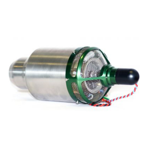
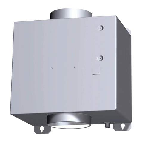
Bettcher Ultra Drive UN-99 Guide

BETTCHER
Industries, Inc.
OPERATING INSTRUCTIONS AND SPARE PARTS LISTS
ULTRA DRIVE
High Speed Motor
MODEL UN-99
For Use With All Current
Electric Whizard®Trimmers
MODEL 173271 (115V/1/ 60HZ) MANUAL #173299
MODEL 173272 (230V/1/50-60HZ) Issued : April 30, 1999
TMC #796

OPERATING BETTCHER WHIZARD®Ultra Drive High Speed Motor
INSTRUCTIONS INDUSTRIES, INC. Rev. April 17, 2015
Information in this document is subject to change without notice.
No part of this document may be reproduced or transmitted in any form or any
means, electronic or mechanical, for any purpose, without the express written
permission of Bettcher Industries Inc.
Written permission to reproduce in whole or part is herewith granted to the legal
owners of the Whizard®Ultra Drive High Speed Motor with which these
Operating Instructions have been supplied.
Operating Instructions in other languages are available on request. Additional
copies of Operating Instructions are available by calling or writing the local
Representative or by contacting :
BETTCHER INDUSTRIES, INC.
P.O. Box 336
Vermilion, Ohio 44089
U.S.A.
Telephone : 1-440-965-4422
(In The U.S.A.) : 1-800-321-8763
Fax : 1-440-328-4535
The Information Provided In These Operating Instructions
Are Important To Your Health, Comfort And Safety.
For Safe And Proper Operation, Read This Entire
Manual Before Using This Equipment.
Copyright 1999 By Bettcher Industries, Inc.
All Rights Reserved
Original Instructions
Page i

OPERATING BETTCHER WHIZARD®Ultra Drive High Speed Motor
INSTRUCTIONS INDUSTRIES, INC. Rev. April 17, 2015
Table Of Contents
SECTION 1.0 Machine Specifications 1
SECTION 2.0 Designated Use 2
2.1 Warning 2
2.2 Recommended Operation 3
SECTION 3.0 Function 4
3.1 Machine Function Description 4
3.2 Safety Recommendations And Warnings 4
SECTION 4.0 Safety Features 6
SECTION 5.0 Installation 6
5.1 Mounting Position 6
5.2 Mounting Drive Unit 8
5.3 Attaching Flex Shaft/Casing Assembly 8
5.4 Power Source Connection 8
SECTION 6.0 Instructions For Operation 9
6.1 Storing Trimmer 9
6.2 Removing Trimmer 10
6.3 Turning The Unit On 10
6.4 Turning The Unit Off 11
6.5 Control Panel 11
6.6 Fault Detection And Correction/Wiring Diagram 12
Page ii

OPERATING BETTCHER WHIZARD®Ultra Drive High Speed Motor
INSTRUCTIONS INDUSTRIES, INC. Rev. April 17, 2015
Table Of Contents
(Continued)
SECTION 7.0 Maintenance 15
7.1 Controller Assembly 15
7.2 Hanger Assembly 16
7.3 Belt Drive Assembly 16
7.4 Enclosure/Frame/Motor Assembly 17
7.5 Preventative Maintenance 17
SECTION 8.0 Cleaning 17
SECTION 9.0 Spare Parts List
9.1 Drive Unit Assembly 18
9.2 Controller Sub-Assembly 20
9.3 Hanger Sub-Assembly 22
SECTION 10.0 About These Operating Instructions 24
10.1 Other Languages 24
10.2 Document Identification 24
10.3 Software And Duplication 24
SECTION 11.0 Contact Addresses And Phone 25
Page iii

OPERATING BETTCHER WHIZARD®Ultra Drive High Speed Motor
INSTRUCTIONS INDUSTRIES, INC. Rev. April 17, 2015
SECTION 1.0 Machine Specifications
The Bettcher Whizard®Ultra Drive High Speed Motor is designed with the highest
possible standards for safety in addition to high production efficiency.
The Whizard®Ultra Drive High Speed Motor Assembly described in this Operation
Instruction has been tested by an independent and certified body, Underwriter’s
Laboratory (UL/CUL/CE), and complies with the Low Voltage Directive 73/23/EEC
and EMC 89/336/EEC which includes conformity with the following standards :
• EN 50081-1
• EN 55014-1/02.97
• EN 50082-1
• EN 55014-2/02.97
• EN 60335-1
• EN 61000-3-2/04.95
• IEC 335-1
• EN 61000-3-3/01.95
In addition, this product also conforms with the following American standards :
ANSI 3.34 and UL763.
Power Requirements:
Model 173271
115 VAC / 1 Phase / 60 Hz
5.2 Full Load Amps
Model 173272
230 VAC / 1 Phase / 50-60 Hz
2.5 Full Load Amps
General Whizard®Ultra Drive High Speed Motor Information:
Weight
35 lbs.
Overall Size
12" Wide x 9 1/4" Deep x 22 1/2" Long
Page 1

OPERATING BETTCHER WHIZARD®Ultra Drive High Speed Motor
INSTRUCTIONS INDUSTRIES, INC. Rev. April 17, 2015
SECTION 2.0 Designated Use
2.1 Warning
WARNING
WHIZARD®TRIMMERS ARE USED FOR REMOVAL OF FAT
AND TISSUE, THE RECOVERY OF LEAN MEAT FROM FAT
AND AS AUNIVERSAL CUTTING TOOL IN THE MEAT
INDUSTRY. ANY USE IN APPLICATIONS OTHER THAN
THOSE FOR WHICH THE WHIZARD®TRIMMERS HAVE BEEN
DESIGNED AND BUILT MAY RESULT IN SERIOUS INJURIES.
WARNING
THE MANUFACTURER ASSUMES NO LIABILITY FOR ANY
UNAUTHORIZED DESIGN CHANGES, MODIFICATIONS, OR USE OF
PARTS NOT SUPPLIED BY THE MANUFACTURER
OR
THE USE OF PARTS NOT DESIGNED
FOR USE ON THE SPECIFIC MODEL
AND
INCLUDES CHANGES IN OPERATING PROCEDURES
MADE BY THEOWNER OR ANY OF HIS PERSONNEL.
THE USE OF PARTS OTHER THAN THOSE LISTED IN
THE PARTS LIST OF THIS MANUAL MAY CAUSE
BLADE LOCK-UP RESULTING IN AN UNSAFE
OPERATING CONDITION.
FOR SAFE AND PROPER OPERATION, READ ENTIRE
MANUAL BEFORE USING THIS EQUIPMENT.
Page 2

OPERATING BETTCHER WHIZARD®Ultra Drive High Speed Motor
INSTRUCTIONS INDUSTRIES, INC. Rev. April 17, 2015
2.2 Recommended Operation
The Whizard®Ultra Drive High Speed Motor Assembly has been designed for use
with the following Whizard®Trimmers :
Model Modular Model
350 Trimmer 350M Modular Trimmer
360 Trimmer 360M Modular Trimmer
500 Bone Trimmer
500M
500MA
Modular Bone Trimmer
Modular Angle Bone Trimmer
505 Bone Trimmer
505M
505MA
Modular Defatting Machine
Modular Angle Defatting Machine
520 Bone Trimmer
564M Modular Bone Trimmer
620 Bone Trimmer
620M
620MA
Modular Bone Trimmer
Modular Angle Bone Trimmer
625 Fat Trimmer 625M Modular Fat Trimmer
750 Trimmer
750M
754M
Modular Trimmer
Modular Trimmer
850 Defatting Machine
850M
850MA
Modular Defatting Machine
Modular Angle Defatting Machine
880-B Primal Fat Shaper (Beef) 880B-M Modular Primal Fat Shaper (Beef)
880-S Primal Fat Shaper (Swine) 880S-M Modular Primal Fat Shaper (Swine)
1850 Defatting Machine 1850M Modular Defatting Machine
1880 Primal Fat Shaper 1880M Modular Primal Fat Shaper
1000 Fat And Lean Trimmer 1000M Modular Fat And Lean Trimmer
1300 Primal Fat Shaper 1300M Modular Primal Fat Shaper
1400 Ham Finisher 1400M Modular Ham Finisher
1500 Skinning Machine 1500M Modular Skinning Machine
Page 3

OPERATING BETTCHER WHIZARD®Ultra Drive High Speed Motor
INSTRUCTIONS INDUSTRIES, INC. Rev. April 17, 2015
SECTION 3.0 Function
3.1 Machine Functions
The Whizard® Ultra Drive High Speed Motor has been designed to be used with
all electric driven Bettcher Whizard®Trimmers plus UN84 Quick Release Flex
Shafts and Casings. A custom belt drive and controller provides higher speed
which provides faster blade speed.
A vertical motor drives a flexible shaft. The flexible shaft drives a rotating blade
in the handpiece via a gear and pinion. The force to cut through meat and fats is
provided by the drive motor and no longer by the worker. Forces applied by the
worker are greatly reduced and limited to guiding the rotating knife blade. The
Whizard®Ultra Drive High Speed Motor provides a mechanical advantage for the
operator thus eliminating the need for manual tools such as knives and scissors.
An interlock feature in the hanger prevents turning on the motor while the
Trimmer is in the hanger. A spring loaded latch on the handpiece hanger prevents
the Trimmer from accidentally being knocked out of the hanger.
The motor will also shut off automatically when the Trimmer handpiece is placed
in the hanger.
3.2 Safety Recommendations And Warnings
WARNING
ALWAYS TURN OFF THE MOTOR AND PLACE
THE HANDPIECE IN THE HANGER BRACKET WITH
THE CUTTING BLADE FACING THE MOTOR.
NEVER LAY THE HANDPIECE DOWN ON THE WORKSTATION OR
LET IT HANG FREE BY THE
FLEX SHAFT CASING. NEVER PLACE THE
HANDPIECE IN THE HANGER WHILE THE
BLADE IS STILL REVOLVING.
Page 4

OPERATING BETTCHER WHIZARD®Ultra Drive High Speed Motor
INSTRUCTIONS INDUSTRIES, INC. Rev. April 17, 2015
3.2 Safety Recommendations And Warnings (Continued)
WARNING
ALWAYS DISCONNECT THE POWER AND REMOVE THE
TOOL FROM THE FLEX SHAFT PRIOR TO SERVICING.
WARNING
ELECTRICAL SHOCK MAY OCCUR !
USE ONLY 3WIRE GROUND TYPE CONNECTOR WHICH IS
FURNISHED WITH THE MACHINE. THIS MUST BE CONNECTED TO
AN EARTH GROUND VIA ASUITABLE GROUNDED THREE
CONDUCTOR RECEPTACLE.
AVOID USE OF THIS MACHINE IN STANDING WATER.
WARNING
IF AT ANY TIME THIS MACHINE DOES NOT APPEAR TO
OPERATE NORMALLY OR EXHIBITS AMARKED CHANGE
IN PERFORMANCE, IT SHOULD BE IMMEDIATELY
SHUT DOWN AND TAGGED AS "UNSAFE" UNTIL
SUCH TIME AS PROPER REPAIRS ARE MADE
THE MACHINE AGAIN OPERATES NORMALLY. FOLLOW
YOUR COMPANY’S LOCKOUT/TAGOUT PROCEDURES.
WARNING
SHARP BLADE MAY CAUSE CUT INJURY!
FOR PROPER PROTECTION OF HANDS, AMETAL MESH GLOVE
SHOULD BE USED ON THE NON-KNIFE HAND WHEN OPERATING
THIS EQUIPMENT AND APROTECTIVE GLOVE USED DURING THE
HANDLING OF BLADES.
Page 5

OPERATING BETTCHER WHIZARD®Ultra Drive High Speed Motor
INSTRUCTIONS INDUSTRIES, INC. Rev. April 17, 2015
SECTION 4.0 Safety Features
Strain relief design allows motor to be free-swinging.
The machine has an interlock on the handpiece hanger that prevents hanging the
handpiece while the motor is running or turning the motor on while the handpiece
is in the hanger. A spring loaded latch on the handpiece hanger prevents the
trimmer from accidentally being knocked out of the hanger.
The motor will shut off automatically if the handpiece is placed into the hanger.
WARNING
WORKER FATIGUE MAY INCREASE AND EFFICIENCY
DECREASE IF RECOMMENDED INSTALLATION DIMENSIONS
ARE NOT FOLLOWED!
IMPROPERLY HUNG MOTORS MAY RESULT IN
EXCESSIVE OPERATOR EFFORT AND
ADECREASE IN MOBILITY.
SECTION 5.0 Installation
5.1 Mounting Position
Correct installation is extremely important to achieve maximum efficiency for
both the Whizard®unit and the operator. Incorrect installation may possibly
hamper the operator's movements and cause undue wear or damage to the flex
shaft and flex shaft casing parts of the unit.
The yoke should be rigidly mounted and parallel to the work station.
A 3/4 inch diameter pipe should be fastened to an overhead beam and be long
enough to position the yoke as shown in Figure #1.
Page 6

OPERATING BETTCHER WHIZARD®Ultra Drive High Speed Motor
INSTRUCTIONS INDUSTRIES, INC. Rev. April 17, 2015
5.1 Mounting Position (Continued)
For further details on the ergonomic design considerations to the work station,
please refer to the Whizard®Trimmer Ergonomic Manual. Copies may be
obtained by making the request to Bettcher Industries at the contact locations
listed in the back of this manual.
CASING SIZE
A
B
C
Small Diameter-Short
12”
12”
49½”
Small Diameter-Long
12”
12”
61½”
Small Diameter – Extra Long
12”
12”
61½” *
Large Diameter
12”
15”
63½”
Large Diameter – Extra Long
12”
*
63½” *
Dimension A = Distance
Offset From Shoulder
Dimension B = Distance Out
From Table Top
Dimension C = Distance Above
Cutting Level
It Is Strongly Recommended That A Safety Cable Or Chain
Be Installed Through The Yoke And Around A Fixed Overhead Structure.
* Application Dependent; Distances Can
Be Adjusted As Needed
Figure #1
Page 7

OPERATING BETTCHER WHIZARD®Ultra Drive High Speed Motor
INSTRUCTIONS INDUSTRIES, INC. Rev. April 17, 2015
5.2 Mounting Drive Unit
ALWAYS REMOVE THE FLEX SHAFT/ CASING ASSEMBLY AND TRIMMER
FROM THE DRIVE UNIT PRIOR TO MOUNTING OR REMOVING THE DRIVE
UNIT.
Hold the drive unit so the controller side is pointing down and parallel to the floor.
Lift the drive unit up and through the yoke opening aligning the flats on the pivots of
the drive unit with the slots in the yoke inserts. Then lower the drive unit into the
inserts and carefully allow the drive unit to slowly rotate to it's vertical position. The
drive unit should swivel freely in the yoke.
The hanger should appear on the right side when facing the front of the unit.
To remove the drive unit from the yoke, rotate the drive unit so the controller side is
pointing down and parallel to the floor, then lift up and out of the yoke.
5.3 Attaching Flex Shaft/Casing Assembly
Install the flex shaft/casing assembly to the motor disconnect by lifting the disconnect
collar and inserting the adapter end of the casing into the disconnect body. It may be
necessary to rotate the casing assembly to align the square drive of the flex shaft with
the square hole in the motor shaft adapter. Release the disconnect collar to secure the
casing to the motor assembly. The flex shaft/casing assembly should swivel freely.
5.4 Power Source Connection
Connect the motor power cord to the prescribed voltage using a three (3) prong
grounded plug. (Line power, neutral, and ground). (See Wiring Diagram in Section
6.6)
Yoke
Pivot
Hanger
Drive Unit
Lift Up and
Through Yoke
Lower Pivots Down
into the Slots of the
Yoke
Swing Unit to
Vertical Position
Right Side View
Front View
Figure #2
Controller Facing
Toward the Floor
Page 8

OPERATING BETTCHER WHIZARD®Ultra Drive High Speed Motor
INSTRUCTIONS INDUSTRIES, INC. Rev. April 17, 2015
SECTION 6.0 Instructions For Operation
6.1 Storing Trimmer (Refer To Figure #3A)
To place the Trimmer in the hanger, swing the Latch with your left hand to the left
and lift up the Handpiece Bracket to the full raised position (the Latch and Bracket
are attached to one another). Place the Trimmer onto the Peg by sliding the inside
diameter of the Trimmer blade (or depth gage) fully on to the Peg against the
Striker Plate and lower the Bracket down so it's inside surface rests on the front
edge of the Trimmer blade housing.
The Trimmer is now captured in the hanger. The spring loaded Latch will prevent
the Trimmer from being accidentally knocked out the hanger.
Figure #3A
To Place Trimmer In Hanger
STRIKER
PLATE
LATCH
PEG
TRIMM ER
HANDPIECE
BRACKET
SLIDE LATCH TO
LEFT AND LIFT UP. LOWER HANDPIECE
BRACKET TO REST ON
OUTSIDE DIAM ETER OF
TRIMMER BLADE
HOUSING.
PLACE INSIDE
DIAMETER OF
TRIM M ER BLADE
AREA OVER PEG.
NOTE: Latch and Handpiece Bracket
are Connected and Move Together
Page 9

OPERATING BETTCHER WHIZARD®Ultra Drive High Speed Motor
INSTRUCTIONS INDUSTRIES, INC. Rev. April 17, 2015
6.2 Removing Trimmer (Refer To Figure #3B)
To remove the Trimmer from the hanger, firmly grasp the handpiece by it's handle with
your dominant hand and swing the Latch with your opposite hand to the left and lift the
Bracket to its fully raised position, then carefully remove the Trimmer from the Peg.
Figure #3B
To Remove Trimmer From Hanger
6.3 Turning The Unit On (Refer to Figure #3C)
To turn the drive unit ON, remove the Trimmer from the hanger and pull down on the
switch Slider.
SLIDE LATCH TO LEFT
AND LIFT UP.
REMOVE TRIMMER
FROM PEG.
LOWER LATCH/HANDPIECE
BRACKET.
PULL DOWN SLIDER
TO TURN ON
Figure #3C
Page 10

OPERATING BETTCHER WHIZARD®Ultra Drive High Speed Motor
INSTRUCTIONS INDUSTRIES, INC. Rev. April 17, 2015
6.4 Turning The Unit Off (Refer to Figure #3D)
There are two ways to turn the drive unit OFF: One is to push up on the switch Slider.
The second way is to lift the Latch/Handpiece Bracket with your hand or by placing the
front portion of the Trimmer blade housing in the "lip" area of the Bracket and lift up
with the Trimmer in hand.
6.5 Control Panel (Refer to Figure #3E)
On the controller panel at the rear of the drive unit you will find the following features:
●Power Cord And Strain Relief Connector
●Unit Specification Plate
●Warning Plate
Figure #3D
Two Methods to
Turn Unit Off
Lip of Bracket
PUSH UP ON LIP OF BRACKET WITH
FRONT PORTION OF TRIMMER
BLADE HOUSING TO TURN OFF.
Latch
Slider
PUSH UP ON SLIDER OR
LATCH TO TURN OFF.
Power Cord
Strain Relief Connector
Warning Plate
Specification Plate
Figure #3E
Page 11

OPERATING BETTCHER WHIZARD®Ultra Drive High Speed Motor
INSTRUCTIONS INDUSTRIES, INC. Rev. April 17, 2015
6.6 Fault Detection And Correction/Wiring Diagram
Problem Probable Cause Remedy
Switch On, Motor
Will Not Start
No input power. Check power plug.
Check input power.
Power switch failure.
Check power at switch
wires. Replace switch.
Refer to Section 7.2.
Motor failure.
Check connections inside
control panel assembly.
Replace motor.
Refer to Section 7.4.
Capacitor failure. Replace capacitor.
Refer to Section 7.1.
Contactor failure.
Check power in and out of
contactor. Replace
contactor.
Refer to Section 7.1.
Motor Stops While
Operating Motor failure. Replace Motor.
Refer to Section 7.4
Motor Runs But Flex
Shaft Does Not Rotate
Broken belt. Replace belt.
Refer to Section 7.3.
Loose sprocket. Tighten sprocket.
Worn drive adapter. Replace drive adapter.
Page 12

OPERATING BETTCHER WHIZARD®Ultra Drive High Speed Motor
INSTRUCTIONS INDUSTRIES, INC. Rev. April 17, 2015
6.6 Fault Detection And Correction/Wiring Diagram (Continued)
WIRING DIAGRAM
HANGER
SWITCH
NO
Page 13

OPERATING BETTCHER WHIZARD®Ultra Drive High Speed Motor
INSTRUCTIONS INDUSTRIES, INC. Rev. April 17, 2015
THIS PAGE INTENTIONALLY LEFT BLANK
Page 14

OPERATING BETTCHER WHIZARD®Ultra Drive High Speed Motor
INSTRUCTIONS INDUSTRIES, INC. Rev. April 17, 2015
SECT ION 7 .0 Maintenance
WARNING
DISCONNECT POWER BEFORE
SERVICING OR DISASSEMBLING.
The Drive Unit has been designed in four main sub-assemblies :
1. Controller Assembly
2. Hanger Assembly
3. Belt Drive Assembly
4. Enclosure/Frame/Motor Assembly
7.1 Controller Assembly (Refer to Control Panel PartsList Section 9.2)
Remove the six screws which hold the controller to the drive unit. Carefully pull the
controller out through the opening in the drive unit. Remove the four junction box cover
screws and remove the cover to access the interior of the controller assembly.
Remove the capacitor by pulling it up out of it’s bracket. The capacitor cap will become
loose from the capacitor. Loosen the motor and hanger switch connections and strain
reliefs. Remove the motor and switch cables from the box.
Remove the two screws for the contactor. Remove the two screws holding the capacitor
bracket.
Refer to the Controller Assembly Parts List for serviceable components.
For reassembly, reverse the above procedure. Refer to Wiring Diagram Section 6.6 for
electrical connections.
The hanger switch cable and motor cable should run along the sides of the motor so not to
come in contact with the motor fan.
Page 15

OPERATING BETTCHER WHIZARD®Ultra Drive High Speed Motor
INSTRUCTIONS INDUSTRIES, INC. Rev. April 17, 2015
7.2 Hanger Assem bly (Refer to Hanger PartsList Section 9.3)
Remove the controller assembly as described in Section 7.1
Remove the two striker plate screws and remove the striker plate, peg, guard assembly,
cover plate, actuator, spring, and slider. Remove the four screws and washers holding the
housing to the drive unit. The switch wire harness will come through the clearance hole
in the drive unit frame and enclosure.
To remove the switch, remove the two screws. Remove the switch base by removing the
two screws and washers.
For reassembly, reverse the above procedures.
7.3 Belt Drive Assembly (Refer to DriveUnit PartsList 9.1 )
Remove the casing disconnect assembly from the cover.
Remove the six screws and washers from the housing cover. Lift the housing cover
straight off the housing assembly. If needed, there are screw-driver slots on the edge of
the housing assembly, which will aid in prying the housing cover from the housing
assembly.
Using a 1/8 hex wrench, remove the two set screws from the timing pulley tapered
bushing. Break loose the tapered bushing from the motor shaft by installing one of the set
screws into the third hole of the bushing and tighten down until the bushing and pulley
separate.
Remove the tapered bushing and pull the timing pulley, shaft key, timing belt and pulley
assembly from the housing assembly. Remove the four nuts and washers holding the
housing assembly to the frame.
It is not necessary to remove the timing pulley and tapered bushing to remove the belt
and pulley assembly. Place two screwdrivers between the pulley flange and the housing
then pry the pulley straight out of the housing.
Note: For pulley assembly bearing service, it is recommended that the entire assembly be
purchased and changed as a unit since bearing press fit (tolerance) is critical. Incorrect
assembly will result in bearing failure.
For reassembly, reverse the above procedure. The flanges of the pulleys are to be in line
with each other.
Page 16
Table of contents
