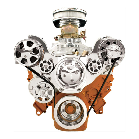
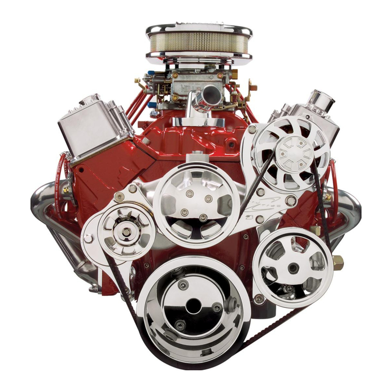
Billet Specialties Tru Trac # 13805 User manual

Small Block Chrysler
Installation Manual
For Systems without A/C
#13805 / #13825
Billet Specialties, Inc.
500 Shawmut Avenue.
La Grange, Illinois 60526
Tech Line (708) 588-0505
Fax (708) 588-7181

Required Tools & Materials
Anti-seize Compound
RTV Silicone
Permatex Hylomar® (Gasket Dressing)
Gasket Scraper
Scotch-Brite®Pad
3/8-16 Thread Chaser* & Holder
*Thread chasers are available at your local
parts store and are different from a thread
cutting tap.
PLEASE READ ALL INSTRUCTIONS BEFORE INSTALLING ANY
COMPONENTS OF THE TRU TRAC SERPENTINE SYSTEM
5/32” Allen
7/32" Allen
1/4" Allen
5/16" Allen
5/8” Box End Wrench
11/16” Box End Wrench
3/4” Box End Wrench
Socket Wrench & Extension
3/8" 12-point socket
10mm 12-point socket
12mm 12-point Socket
Tech Line: 708.588.0505
Fax: 708.588.7181
www.billetspecialties.com
TECH TIP:
Billet Specialties recommends the use of Anti-Seize on all
fasteners to prevent thread lock-up.
5/16-18 x 2-3/4" Socket Head Cap Screw
Power Steering Pump To Bracket
x2
3/8-16 x 3/4" Socket Head Cap Screw
Power Steering Bracket To Alternator Bracket
x2
5/16" Lock Washer
x2
Skin Board #1 - Packaged With Power Steering Pump
Skin Board #2 - Packaged With Water Pump
7/8" Spacer Nut x4
1-11/32" Spacer Nut x2
2-3/8" Spacer Nut x1
3/8-16 Zinc Coated
Hex Nuts
(Discard After Use)
x2
3/8-16 x 2-1/2" Block Mounting Stud x2
3/8-16 x 5-1/2" Block Mounting Stud x4
Prepping The Block
Disconnect battery and remove all existing accessory drive brackets &
components from motor.
Remove water pump and mechanical fuel pump, scrape away any
existing gasket material with a gasket scraper and dress surface with a
Scotch Brite® pad.
Remove the timing bolt on the passenger side of the motor just below the
fuel pump.
Note: If you wish to replace the timing cover gaskets and seals now is the time to do so.
Fel-Pro makes a timing cover gasket set P/N TCS 6563-1 that covers all of them.
THIS KIT IS NOT DESIGNED FOR USE WITH A
MECHANICAL FUEL PUMP
3/8-16 x 1-1/4" Block Mounting Stud x1
3-1/2" Spacer Nut x1

3/8-16 x 3/4" 12-Point Cap Screw
Tensioner Pulley
x1
8mm-1.25 x 25mm 12-Point Cap Screw
Bridge Bracket
x1
3/8-16 x 1-1/2" 12-Point Cap Screw
Water Pump To Block
x1
3/8-16 x 1-3/4" 12-Point Cap Screw
Idler Pulleys
x3
10mm-1.25 x 70mm 12-Point Cap Screw
Alternator - Lower Bolt
x1
3/8-16 x 2-3/4" Button Head Cap Screw
Timing Cover To Block
x1
3/8-16 x 1" Flat Head Cap Screw
Thru Bridge Bracket Into Spacer Nuts
x6
5/16-18 x 3/4" Flat Head Cap Screw
Thru Bridge Bracket Into Tensioner
x3
3/8-16 x 1-1/4" Socket Head Cap Screw
Tensioner Bracket Assembly
x2
3/8-16 x 1" Socket Head Cap Screw
Thru back Of Tensioner Bracket To
Tensioner Spacer Nut
x1
5/16-18 x 1" Socket Set Screw
Tensioner Assembly
x1
5/16-18 x 3/4" Socket Head Cap Screw
Water Pump Pulley
x4
5/16-18 x 1" Socket Head Cap Screw
Crank Pulley
x6
5/16" Belleville Washer
x6
Skin Board #3 - Packaged In Main Box
Serpentine Belt
Goodyear Poly-V 6-Rib Serpentine Belt - 66" #4060660 (with power steering)
Goodyear Poly-V 6-Rib Serpentine Belt - 63.5" #4060635 (without power steering)
3/8-16 x 3/4" Button Head Cap Screw
Fuel Pump Block-Off
x2
Packaged With Fuel Pump Block-Off

www.billetspecialties.com
www.billetspecialties.com
7
Figure 1: Install Fuel Pump Block-Off
A] Sparingly apply RTV silicone to the timing cover surface and gasket.
Attach the fuel pump block off with the two 3/8-16 x 3/4” button head
cap screws and tighten rmly.
B] Thread the 3/8-16 x 2-3/4” button head cap screw into the timing cover
by the fuel pump block off and tighten rmly.
Figure 2: Install Block Mounting Studs
Apply RTV silicone to one end of the four 3/8-16 x 5-1/2” threaded studs
and the two 3/8-16 x 2-1/2” threaded studs.
A] Thread the silicone side of the 5-1/2” studs into the upper four holes in
the timing cover.
Important! Leave 2-7/16” of thread exposed from the timing cover face.
B] Thread the silicone side of the two 2-1/2” studs into the bottom two
holes of the timing cover.
Important! Leave 2” of thread exposed.
Double-check your lengths.
The studs can easily be tightened by threading two 3/16” zinc coated
nuts (supplied) onto the stud and tighten them against each other to act
as a drive nut (discard after use).
*Example
A
B
2-7/16" From Timing Cover 2" From Timing Cover
A B

www.billetspecialties.com
www.billetspecialties.com
9
Figure 3: Install Water Pump
Coat both sides of water pump gasket with Permatex Hylomar gasket
dressing. Install gasket over studs.
A] Slide the water pump over the studs and into position. Apply anti-seize
to the threads of the 3/8-16 x 1-1/2” 12-point ARP cap screw and thread
into top water pump hole, nger tighten.
Apply anti-seize to the exposed threads on the remaining studs.
B] Finish by threading the two 1-11/32” spacer nuts to the bottom two
studs and nger tighten.
Figure 4: Install Tensioner Bracket
Apply anti-seize to the two 3/8-16 x 1-1/4” socket head cap screws.
A&B] Assemble front and rear tensioner bracket halves together with the
two 3/8” cap screws and tighten rmly.
C] Place completed bracket on passenger-side of water pump and se-
cure with two 7/8” spacer nuts and nger tighten.
D] Apply Loc-Tite to one end of the 3/8-16 x 1-1/4” threaded stud and
thread it into the 3-1/2” long spacer nut until it bottoms out.
E] Apply anti-seize to the remaining exposed threads and install the
3-1/2” spacer nut into the tensioner bracket using the top open hole.
Tighten rmly.
A
B
A
B
D
C
E

www.billetspecialties.com
www.billetspecialties.com
11
FOR KITS WITHOUT POWER STEERING – SKIP TO STEP B
Figure 5: Install Alternator & Power Steering Bracket
A] Apply anti-seize to the two 3/8-16 x 3/4” socket head cap screws.
Assemble power steering bracket to the back of the alternator bracket
and tighten rmly.
B] Place alternator bracket on driver side water pump and secure with
two 7/8” spacer nuts.
Tighten all water pump spacer nuts at this time rmly in a cross pattern,
make sure bracket fasteners are also tightened rmly.
Now is a good time to install the
barbed ttings in the water pump.
Figure 6: Install Bridge Bracket
Apply anti-seize to the six 3/8-16 x 1" at head cap screws.
Place bridge bracket to motor and align mount holes with the six water
pump spacer nuts.
Thread the 3/8” at head screws through the bridge bracket and into the
water pump spacer nuts, nger tighten only.
A B
1
2
3
45
6

www.billetspecialties.com
www.billetspecialties.com
13
Figure 7: Install Tensioner
A] Apply Loc-Tite to one end of the 5/16-18 x 1” socket set screw and
thread into the back of the tensioner body, nger tighten.
B] Apply anti-seize to the remaining exposed threads of the setscrew.
Thread the 2-3/8” long spacer nut onto the stud and tighten rmly.
ABC
D
E
Figure 8: Install Tensioner Continued
Apply anti-seize to the threads of the three 5/16-18 x 3/4” at head cap
screws and the 3/8-16 x 1” socket head cap screw.
C&D] Place tensioner assembly between the tensioner bracket and the
bridge bracket. Thread two 5/16” athead cap screws through the bridge
bracket and into the tensioner body, nger tighten. Thread the third
5/16-18 x 3/4” at head cap screw through the bridge bracket and into
the 3-1/2” spacer nut, nger tighten.
E] Thread the 3/8” socket head cap screw through the back of the
tensioner bracket and into the tensioner spacer nut, tighten rmly.

www.billetspecialties.com
www.billetspecialties.com
15
FOR KITS WITHOUT POWER STEERING – CONTINUE TO FIGURE 11
Figure 10: Install Power Steering Pump With Pulley
Apply anti-seize to the threads of the two 5/16-18 x 2-3/4” socket head
cap screws.
Place power steering pump with pulley on bracket and align.
Thread the two 5/16-18 x 2-3/4” cap screws with 5/16” lock washers
through the power steering pump mount bosses and into the power
steering bracket, tighten rmly 26ft/lbs.
Figure 9: Install Alternator
Apply anti-seize to the 8mm-1.25 x 25mm ARP 12-point cap screw and the
10mm-1.25 x 70mm ARP 12-point cap screw.
A] Place alternator between bridge bracket and alternator bracket, align
alternator bosses with the bridge bracket. Thread the 10mm ARP 12-point
cap screw through the bottom bridge bracket hole and alternator into
the alternator bracket, nger tighten.
B] Thread the 8mm ARP 12-point cap screw through the bridge bracket
and into the top alternator boss.
Tighten all fasteners rmly at this time: All ARP 12-point fasteners and at
head bridge bracket screws.
A
B

www.billetspecialties.com
www.billetspecialties.com
17
Figure 11: Install Crankshaft Pulley
Apply Loc-Tite to the threads of the six 5/16-18 x 1” socket head
cap screws.
A] Place crankshaft pulley on damper and align holes.
B&C] Thread the 5/16” cap screws with a Belleville washer
(cup side towards pulley) through the pulley and into the crankshaft,
tighten rmly 26ft/lbs.
Figure 12: Install Water Pump Pulley
Apply Loc-Tite to the threads of the four 5/16-18 x 3/4” socket head cap
screws.
Place water pump pulley on water pump and align holes.
Thread the 5/16” cap screws through the pulley and into the water pump
ange, tighten rmly 26 ft/lbs.
A B
C

www.billetspecialties.com
www.billetspecialties.com
19
Figure 13: Install Idler Pulleys
Apply Loc-Tite to the threads of the three 3/8-16 x 1-3/4” ARP 12-point cap
screws.
A] AC Delete Idler Pulley: Thread a 3/8” ARP 12-point cap screw with
aluminum washer through the large idler pulley and pulley boss into the
bridge bracket and tighten rmly 46ft/lb.
B&C] Small Idler Pulleys: Thread the second 3/8” ARP 12-point cap screw
through the small idler pulley-cover, pulley and pulley boss into the bridge
bracket and tighten rmly, 46ft/lb. Repeat for other side.
A B
C
Figure 15: Install Belt &
Tensioner Pulley
A] Apply anti-seize to one
3/8-16 x 3/4” ARP 12-point cap
screw.
Route serpentine belt as shown
below - minus tensioner pulley.
Place a 5/8” box end wrench
on tensioner.
B] Align belt onto pulley and pull up
on wrench to release tension until
tensioner pulley slips onto
tensioner shaft.
Slowly return wrench to starting
position to apply tension to belt.
C] Remove wrench and install the
3/8-16 x 3/4” ARP 12-point cap
screw with thrust washer onto pulley
and tighten rmly (46 ft/lbs).
A
B
C
With Power Steering Without Power Stering

Billet Specialties, Inc.
500 Shawmut Avenue
La Grange, Illinois 60526
Tech Line 708.588.0505
Fax 708.588.7181
www.billetspecialties.com
#13805/ #13825
This manual suits for next models
1
Other Billet Specialties Engine manuals
Popular Engine manuals by other brands

MINN KOTA
MINN KOTA RIPTIDE POWERDRIVE owner's manual

SEW-Eurodrive
SEW-Eurodrive CMP40 Revision

Lowrance
Lowrance Ghost Series installation manual
DLE
DLE DLE55RA user manual
Briggs & Stratton
Briggs & Stratton 133200 Series Operating & maintenance instructions
Perkins
Perkins 1206F-E70TTA Operation and Maintenance Instructional Manual
