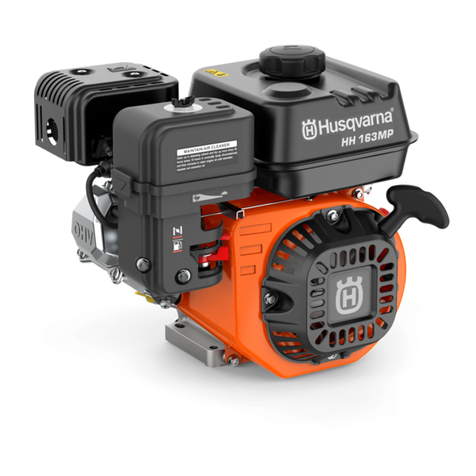
Husqvarna HH 389MPC User manual

HH163MP, HH196MP, HH196OB, HH212OB, HH270MP,
HH270OB, HH389MP, HH 389MPC, HH389OB
EN Operator's manual 2-17
ES Manual de usuario 18-35
PT-BR Manual do operador 36-53

Contents
Introduction..............................................2
Safety...................................................... 5
Assembly.................................................6
Operation.................................................7
Maintenance............................................9
Troubleshooting.....................................13
Transportation, storage and disposal.... 14
Technical data....................................... 15
Introduction
Engine overview
1
6
13
11
8
10
14
12
15
4
7
3
2
9
5
1. Muffler
2. Spark plug
3. Air filter
4. Choke control
5. Fuel valve lever
6. Throttle control
7. Recoil starter
8. Starter rope handle
9. Fuel tank cap
10. Fuel tank
11. Engine ON/OFF switch
12. Serial number
13. Drain plug for engine oil
14. Oil tank cap and dipstick
15. Operator's manual
21537 - 003 - 18.11.2022

Engine overview (HH212OB)
1
2
3
13
4
11
12 14
15
6
5
8
9
10
7
16
1. Exhaust pipe
2. Ignition cable
3. Air filter
4. Choke control
5. Fuel valve lever
6. Throttle control
7. Recoil starter
8. Starter rope handle
9. Fuel tank
10. Fuel tank cap
11. Engine ON/OFF switch
12. Drain plug for engine oil
13. Serial number
14. Oil tank cap and dipstick
15. Spark plug
16. Operator's manual
Product description
This engine is a 4-stroke combustion engine.
Intended use
The engine must only be used outdoors or in areas with
sufficient airflow.
Choke control
The choke control opens and closes the choke valve in the
carburetor. The choke control position (A) is used during
start of a cold engine.
A
The choke control position (B) is used after start of a cold
engine and during start of a warm engine.
B
1537 - 003 - 18.11.2022 3

Fuel valve
The fuel valve opens and closes the flow of fuel between
the fuel tank and the carburetor. When the fuel valve lever
is in position (A), the fuel valve is open.
A
When the fuel valve lever is in position (B), the fuel valve is
closed.
B
Throttle control
The throttle control (A) sets the engine speed. The position
to the far right is the highest speed. The position to the far
left is the lowest speed.
A
Serial number
Refer to
Engine overview on page 2
for the position of
the serial number. Supply the model name and the serial
number when you send an order for spare parts.
Symbols on the product
WARNING! This product can be dangerous
and cause serious injury or death to the
operator or others. Be careful and use the
product correctly.
Read the operator's manual carefully
and make sure that you understand the
instructions before use.
Choke.
Fuel valve.
High engine speed.
Low engine speed.
Engine oil.
Risk of fire.
Do not breathe in exhaust fumes. The
exhaust fumes from the engine contain
carbon monoxide, an odorless, poisonous
and very dangerous gas. Do not start the
engine indoors or in closed spaces.
Hot surface.
Note: Other symbols/decals on the engine refer to
certification requirements for some commercial areas.
Product liability
As referred to in the product liability laws, we are not liable
for damages that our product causes if:
• the product is incorrectly repaired.
• the product is repaired with parts that are not from the
manufacturer or not approved by the manufacturer.
• the product has an accessory that is not from the
manufacturer or not approved by the manufacturer.
• the product is not repaired at an approved service
center or by an approved authority.
41537 - 003 - 18.11.2022

Safety
Safety definitions
Warnings, cautions and notes are used to point out
specially important parts of the manual.
WARNING: Used if there is a risk of injury
or death for the operator or bystanders if the
instructions in the manual are not obeyed.
CAUTION: Used if there is a risk of damage to the
product, other materials or the adjacent area if the
instructions in the manual are not obeyed.
Note: Used to give more information that is necessary in a
given situation.
General safety instructions
WARNING: Read the warning instructions that
follow before you use the engine.
• The engine is dangerous if you are not careful or if you
use the engine incorrectly. There is a risk of injury or
death, or damage to the engine. Before you use the
engine, you must read and understand the contents of
this operator’s manual.
• You must read and understand the operator’s manual
for the product that uses this engine. There can be
more safety instructions for start, stop, operation and
maintenance.
• Save all warnings and instructions.
• Do not let a person operate the engine unless they
read and understand the contents of the operator's
manual.
• Do not let a child operate the engine.
• Do not do modifications to the engine.
Safety instructions for operation
WARNING: Read the warning instructions that
follow before you use the engine.
• Make sure that you know how to stop the engine
quickly in an emergency.
• The exhaust fumes from the engine contain carbon
monoxide which is an odorless, poisonous and very
dangerous gas.
• Do not use a combustion engine product indoors or in
areas that do not have sufficient airflow.
• Do not use the engine in areas where fire or
explosions can occur.
Safety devices on the product
WARNING: Read the warning instructions that
follow before you use the product.
• Do not use a product with defective safety devices.
• Do a check of the safety devices regularly. If the
safety devices are defective, speak to your Husqvarna
service agent.
• Do not make modifications to safety devices.
Engine ON/OFF switch
The engine can only start when the engine ON/OFF switch
is set to "ON". The engine stops when you set the engine
ON/OFF switch to "OFF".
To do a check of the engine ON/OFF switch
1. Start the engine. Refer to
To start the engine on page
8
.
2. Set the engine ON/OFF switch to "OFF". The engine
stops.
Muffler
The muffler keeps the noise levels to a minimum and
sends the exhaust fumes away from the operator.
Do not use the product if the muffler is missing or
defective. A defective muffler increases the noise level and
the risk of fire.
WARNING: The muffler becomes very hot during
and after use and when the engine operates at
idle speed. Be careful near flammable materials
and/or fumes to prevent fire.
To do a check of the muffler
• Examine the muffler regularly to make sure that it is
attached correctly and not damaged.
Fuel safety
WARNING: Read the warning instructions that
follow before you use the product.
• Fuel is flammable and the fumes are explosive. Be
careful with fuel to prevent injury, fire and explosion.
• Do not breathe in the fuel fumes. The fuel fumes are
poisonous and can cause injury. Make sure that the
airflow is sufficient.
• Do not remove the fuel tank cap or fill the fuel tank
when the engine is on.
• Make sure that the engine is cool before you refuel.
• Do not fill fuel in an indoor area. Insufficient airflow
can cause injury or death because of asphyxiation or
carbon monoxide poisoning.
• Do not smoke near the fuel or the engine.
• Do not put hot objects near the fuel or the engine.
• Do not fill fuel near sparks or flames.
• Before you refuel, open the fuel tank cap slowly and
release the pressure carefully.
• Fuel on your skin can cause injury. If you get fuel on
your skin, use soap and water to remove the fuel.
• If you spill fuel on your clothing, change clothing
immediately.
1537 - 003 - 18.11.2022 5

• Do not fill the fuel tank fully. Heat causes the fuel to
expand. Keep a space at the top of the fuel tank.
• Tighten the fuel tank cap fully. If the fuel tank cap is
not tightened, there is a risk of fire.
• Before you start the product, move the product to a
minimum of 3 m/10 ft from where you refueled.
• Do not start the product if there is fuel or engine oil on
the product. Remove the unwanted fuel and engine oil
and let the product dry before you start the engine.
• Examine the engine for leaks regularly. If there are
leaks in the fuel system, do not start the engine until
the leaks are repaired.
• Do not use your fingers to examine the engine for
leaks.
• Keep fuel in approved containers only.
• When the product and fuel is in storage, make sure
that fuel and fuel fumes cannot cause damage.
• Drain the fuel in an approved container outdoors and
away from sparks and flames.
Safety instructions for maintenance
WARNING: Read the warning instructions that
follow before you do maintenance on the engine.
• If the maintenance is not done correctly and regularly,
the risk of injury and damage to the engine increases.
• Stop the engine and make sure that all parts are cool
before you do the maintenance.
• Disconnect the spark plug cap before you do the
maintenance.
• The exhaust fumes from the engine are hot and can
contain sparks. Do not operate the engine in indoor
areas or near flammable material.
• Always use original spare parts. Spare parts that are
not approved by the manufacturer, can cause serious
injury or death.
• Only do the maintenance as given in this operator's
manual. Let an approved service center do all other
servicing.
• Let an approved service center do servicing on the
engine regularly.
Assembly
External throttle control and choke control
The throttle control and choke controls have holes for
installation of cables for optional external controls. The
illustrations show installation examples for a solid wire
cable and for a flexible wire cable.
• If a flexible wire cable is installed, it is necessary to
add a return spring.
• It is necessary to loosen the friction nut for the throttle
control if the throttle is operated with an external
throttle control.
External throttle control assembly
HH163MP, HH196MP, HH196OB, HH212OB:
1
2
3
4
5
9
6
7
8
61537 - 003 - 18.11.2022

HH270MP, HH270OB, HH389MP, HH 389MPC,
HH389OB:
1
2
3
4
5
6
7
9
8
1. Flexible wire
2. Solid wire
3. Wire
4. 4 mm screw (optional)
5. Wire holder (optional)
6. Throttle lever (optional)
7. 5 mm snap ring
8. Friction nut for the throttle lever
9. Return spring
External choke control assembly
HH163MP, HH196MP, HH196OB, HH212OB:
A
B
HH270MP, HH270OB, HH389MP, HH 389MPC,
HH389OB:
A
B
• A: Wire holder.
• B: Choke control lever.
Operation
Introduction
WARNING: Read and understand the safety
chapter before you use the product.
To do before you operate the engine
• Read this operator's manual carefully and make sure
that you understand the instructions.
• Fill engine oil and do a check of the engine oil level.
Refer to
To do a check of the engine oil level on page
10
.
• Do the daily maintenance. Refer to
Maintenance
schedule on page 9
.
• Read the operator's manual for the product that uses
this engine. Obey the procedures that must be done
before you start the product.
To fill fuel
If available, use low-emission/alkylate gasoline. If low-
emission/alkylate gasoline is not available, use good
quality unleaded gasoline or leaded gasoline. Use gasoline
with an octane number of 90 RON out of North America
1537 - 003 - 18.11.2022 7

(87 AKI in North America) or higher, and with a maximum
of 10% ethanol (E10).
CAUTION: Do not use gasoline with an octane
number less than 90 RON out of North America
(87 AKI in North America). This can cause
damage to the product.
1. Open the fuel tank cap slowly to release the pressure.
2. Fill slowly with a fuel can. If you spill fuel, remove it
with a cloth and let remaining fuel dry off.
3. Clean the area around the fuel tank cap.
4. Tighten the fuel tank cap fully. If the fuel tank cap is
not tightened, there is a risk of fire.
5. Move the product a minimum of 3 m (10 ft) from the
position where you filled the tank, before a start.
Oxygenated fuel
Oxygenated fuel is gasoline that is mixed with alcohol or
an ether compound. Some areas use oxygenated fuel to
decrease emissions. The fuel must not contain more than
the given percentages of these oxygenates:
• Ethanol: 27% by volume.
• MTBE: 15% by volume.
• Methanol: 5% by volume.
CAUTION: Fuel that contains methanol must also
contain cosolvents and corrosion inhibitors as
protection for the fuel system.
CAUTION: Oxygenated fuel that contains more
than the given percentages of these oxygenates
voids the warranty. The engine performance can
decrease and the engine can become damaged.
To start the engine
1. Set the fuel valve lever (A) to the ON position.
A
2. Set the choke lever to the correct position.
a) If the engine is cold, close the choke (B).
B
b) If the engine is warm, open the choke (B).
B
3. Apply approximately ⅓ throttle (C).
C
81537 - 003 - 18.11.2022

4. Put the ON/OFF switch (D) to the ON position.
D
5. Pull the starter rope handle (E) slowly until you feel
resistance.
E
6. Pull the starter rope handle quickly and with force until
the engine starts.
7. Move the starter rope handle back slowly into its initial
position to prevent damage to the engine.
8. If the engine is cold, open the choke gradually as the
engine becomes warm.
To set the engine speed
For recommended engine speed, refer to the operator's
manual for the product that uses this engine.
• Move the throttle control (A) to increase or decrease
the engine speed.
A
To stop the engine
1. Move the throttle control to the low speed position.
2. Set the engine ON/OFF switch to OFF. The engine
stops.
3. Move the fuel valve to the OFF position.
Maintenance
Introduction
WARNING: Read and understand the safety
chapter before you do maintenance on the
product.
Maintenance schedule
* = General maintenance done by the operator. The
instructions are not given in this operator's manual.
X = The instructions are given in this operator's manual.
O = This maintenance must be done by a servicing dealer.
All instructions are not given in this operator's manual.
Engine maintenance Before
use, each
10h
After the
first month
or 20h
Each 3
months or
50h
Each 6
months or
100h
Yearly or
each
300h
Each 2
years
Make sure that there are no fuel or oil leaks. *
Make sure that nuts and screws are tightened. *
Look for signs of damage. *
Clean around the muffler and the recoil starter. *
Do a check of the fuel level and the engine oil
level. X
Clean the oil filter. * *
1537 - 003 - 18.11.2022 9

Engine maintenance Before
use, each
10h
After the
first month
or 20h
Each 3
months or
50h
Each 6
months or
100h
Yearly or
each
300h
Each 2
years
Replace the engine oil. X X
Examine the air filter. Clean the air filter if it is
necessary. X
Clean the air filter. Clean at shorter intervals if
the engine is used in a dusty environment. X
Replace the air filter. Applies to paper element
type only. X
Clean the sediment cup. X X
Examine and clean the spark plug. Replace the
spark plug if it is necessary. X X
Replace the spark plug. X
Clean the spark arrestor screen on the muffler. X X
Do a check of the idle speed. X
Adjust the valve head clearance for the air in-
take and the exhaust valves. O
Drain the fuel and clean the fuel tank and the
fuel filter. O
Clean the combustion chamber. O
Examine the fuel line. Replace it if it is neces-
sary. O
To do a check of the engine oil level
The sensor for low oil level automatically stops the engine
before the engine oil level becomes too low but it is
recommended to do a check of the engine oil level before
each start. The sensor for low oil level is not included on
all engine models. Refer to .
CAUTION: Do not operate the engine with low
engine oil level. It can cause damage to the
engine.
CAUTION: Use detergent engine oil for 4-stroke
engines with the viscosity range shown in the
illustration.
-20 0 20 32 40
403020100-10-20-30
F
C
60 80 10050
5W-30
SAE 30
10W-30
1. Stop the engine and make sure that it is level.
2. Remove the oil tank cap and dipstick (A).
C
A
B
3. Clean the oil from the dipstick.
4. Put the dipstick back but do not tighten it.
5. Remove the dipstick.
6. Examine the engine oil level on the dipstick.
7. If the engine oil level is low (B), fill engine oil to the
edge of the oil tank hole (C).
8. Do a check of the engine oil level again.
9. Install the oil tank cap and dipstick.
10 1537 - 003 - 18.11.2022

To replace the engine oil
If the engine is cold, start the engine for 1–2 minutes
before you drain the engine oil. This makes the engine
oil warm and easier to drain.
WARNING: Engine oil is very hot directly after the
engine stops. Let the engine become cool before
you drain the engine oil. If you spill engine oil on
your skin, clean with soap and water.
1. Put a container below the drain plug for the engine oil.
2. Remove the oil tank cap and dipstick (A), the oil drain
plug (B) and the washer (C).
B
A
C
3. Let the oil run out into the container.
4. Install the washer and the oil drain plug. Tighten the oil
drain plug.
5. Fill to the edge of the hole with new engine oil. Refer to
or the engine manual for the correct type of oil.
6. Tighten the oil tank cap.
7. Do a check of the engine oil level.
To clean or replace the air filter
WARNING: Use approved respiratory protection
when you clean or replace the air filter. Discard
used air filters correctly. The dust in the air filter is
dangerous to your health.
WARNING: Do not clean the air filter with
compressed air. This causes damage to the air
filter and the risk increases that you breathe the
dangerous dust.
1. Turn the knob on the air filter cover and remove the air
filter cover (A).
2. Remove the paper filter element (B) and the foam filter
element (C).
A
B
C
D
Note: Some models only have a foam filter element
and not a paper filter element.
3. Clean the air filter housing with a brush.
4. Examine the air filter elements for damage.
CAUTION: Always replace a damaged air
filter, or the dust will go into the engine and
cause engine damage.
5. Tap the paper filter element against a hard surface or
use a vacuum cleaner to remove the particles.
CAUTION: Do not let the nozzle of the
vacuum cleaner touch the surface of the paper
filter element. Keep a small distance. The
sensitive surface of the paper filter element
becomes damaged if objects touch it.
6. Clean the foam filter element with a solution of soap
and water.
7. Flush the foam filter element in clean water.
8. Compress the foam filter element to remove the water
and let the foam filter element dry fully.
9. Lubricate the foam filter element with engine oil.
10. Push a clean cloth against the foam filter element to
remove unwanted oil.
11. Install the air filter in the opposite sequence. Make
sure that the gasket (D) is in the correct position below
the air filter.
To clean the sediment cup
1. Move the fuel valve to the OFF position (A).
1537 - 003 - 18.11.2022 11

2. Remove the sediment cup (B) and the O-ring (C).
B
C
A
3. Clean the sediment cup and the O-ring in solvent that
is not flammable.
4. Let the sediment cup and the O-ring dry fully.
5. Put the O-ring in the fuel valve and install the sediment
cup. Tighten the sediment cup fully.
6. Move the fuel valve to the ON position.
7. Examine the sediment cup for leaks. Replace the O-
ring if there is leakage.
To examine and replace the spark plug
CAUTION: Do not try to start the engine if the
spark plug or ignition cable is removed.
1. Remove the spark plug cap and clean around the
spark plug.
2. Remove the spark plug with a spark plug wrench.
3. Examine the spark plug. Replace it if the electrodes
are burned or if the insulation has cracks or damages.
If the spark plug is not damaged, clean it with a steel
brush.
4. Measure the electrode gap and make sure that it is
correct. Refer to .
a) If it is necessary, bend the side electrode to adjust
the electrode gap.
5. Install the spark plug by hand until it touches the spark
plug seat.
6. Tighten the spark plug with the spark plug wrench.
a) Tighten a used spark plug ⅛–¼ of a turn more,
and a new spark plug ½ turn more.
CAUTION: Spark plugs that are not
tightened correctly can cause damage to
the engine.
7. Install the spark plug cap.
To adjust the idle speed
1. Start the engine outdoors and let it become warm.
2. Move the throttle control to the low speed position.
3. Use a tachometer to do a check of the idle speed.
Refer to for correct idle speed.
4. Turn the idle speed screw (A) clockwise to adjust the
idle speed.
A
To do a check of the spark arrestor screen
WARNING: In some areas and conditions, you
must use a spark arrestor screen to prevent the
risk of fire. Obey local regulations.
1. Remove the 3 screws from the exhaust deflector and
remove the exhaust deflector.
2. Remove the 4 screws (A) from the muffler cover (B)
and remove the muffler cover.
A
B
C
D
12 1537 - 003 - 18.11.2022

3. Remove the screw (C) from the spark arrestor (D) and
remove the spark arrestor from the muffler.
4. Clean the spark arrestor screen carefully with a wire
brush.
5. Examine the spark arrestor screen for wear and
damage. Replace the spark arrestor screen if it is
necessary.
CAUTION: Do not use a product with a
damaged spark arrestor screen.
6. Install the spark arrestor screen in the opposite
sequence.
Carburetor adjustment for high altitude operation
The altitude has an effect on the engine performance and
emissions. If the engine is always operated at altitudes
higher than 1500 m/5000 ft, it is necessary to adjust the
carburetor. Let your servicing dealer do the necessary
adjustments.
CAUTION: Do not operate the engine on lower
altitudes if the carburetor is adjusted for high
altitudes. This causes engine damage. Let your
servicing dealer adjust the carburetor to factory
specifications.
Emission control system
This engine uses lean carburetor adjustments and other
systems to decrease the emissions of dangerous materials
in the exhaust fumes. The air intake, the fuel system
and the exhaust system are parts of the emission control
system. If modifications are done to the emission control
system, the emissions increase.
If modifications are done to the speed adjustment
mechanism or governor linkage, the engine does not
operate as intended. This can also cause increased
emissions.
It is necessary to use original spare parts to make sure
that the emission control system operates correctly.
The engine must be examined and repaired by an
approved servicing dealer if 1 or more of these problems
occur:
• The engine is not easy to start or stops again after a
start.
• The engine does not operate smoothly at idle speed.
• There are misfires in the engine during operation.
• The exhaust smoke is black or the fuel consumption is
high.
Troubleshooting
The engine does not start
Cause Solution
The fuel valve lever is set to the OFF position. Move the fuel valve lever to the ON position.
The choke is open. Close the choke.
The ON/OFF switch is set to the OFF position. Set the ON/OFF switch to the ON position.
There is no fuel in the fuel tank. Fill fuel.
There is unsatisfactory fuel in the fuel tank. Drain the fuel tank and the carburetor. Refer to
To drain the
fuel tank and carburetor on page 14
. Fill with clean fuel.
No fuel stabilizer has been added or the fuel tank has not
been drained before storage.
The spark plug is damaged. Do a check of the electrode gap or replace the spark plug.
The spark plug is wet from fuel. Remove the spark plug and let it dry. Install the spark plug.
CAUTION: Speak to an approved servicing dealer
if the problem stays.
The power of the engine is decreased
Cause Solution
The air filter is clogged. Clean or replace the air filter.
1537 - 003 - 18.11.2022 13

Cause Solution
The fuel tank contains bad gasoline. Drain the fuel tank and the carburetor. Refer to
To drain
the fuel tank and carburetor on page 14
. Fill with clean
gasoline.
No fuel stabilizer has been added or the fuel tank has not
been drained before storage.
The engine speed is set to low. Increase the engine speed.
CAUTION: Speak to an approved servicing dealer
if the problem stays.
Unusual noises come from the engine
Cause Solution
The engine is operated with high
work loads.
No procedure is necessary.
The fuel tank contains bad gaso-
line.
Drain the fuel tank and the carburetor. Refer to
To drain the fuel tank and carburetor
on page 14
. Fill with clean gasoline of a different brand. Speak to an approved
servicing dealer if the problem stays.
CAUTION: Do not continue to operate the engine
if there are unusual noises during standard work
loads. This can cause damage to the engine and
void the warranty.
Transportation, storage and disposal
Transportation
• Let the engine become cool for a minimum of 15
minutes before transportation.
• Keep the engine on a level surface during
transportation to prevent fuel leakage.
• Make sure that the fuel valve lever is in the OFF
position.
To prepare the engine for storage
• Clean the engine.
a) Stop the engine end let it become cool.
b) Clean all external surfaces.
CAUTION: Do not clean with running
water from a hose or a high-pressure
washer. Water that goes into the engine
can cause damages.
c) Apply a thin layer of oil to sensitive areas to
prevent corrosion.
• Add a fuel stabilizer to the fuel tank or drain the fuel
tank and carburetor. Refer to
To add a fuel stabilizer
to the fuel on page 14
and
To drain the fuel tank and
carburetor on page 14
.
• Apply oil to the cylinder. Refer to
To apply oil to the
cylinder on page 15
.
• Put a dust cover on the engine for protection.
• Put the engine in a location with a good airflow and
away from flames and sparks.
• If it is possible, do not put the engine in a location with
high humidity.
To add a fuel stabilizer to the fuel
1. Put the fuel stabilizer in a fuel container with fresh fuel.
2. Fill the fresh fuel with fuel stabilizer into the fuel tank.
3. Start the engine and let it operate outdoors for 10
minutes. This is to make sure that the fuel with the fuel
stabilizer has replaced the fuel without fuel stabilizer.
4. Stop the engine and move the fuel valve lever to the
OFF position.
To drain the fuel tank and carburetor
1. Put an applicable fuel container below the carburetor.
Use a funnel to prevent fuel leakage.
2. Move the fuel valve lever (A) to the OFF position.
A
14 1537 - 003 - 18.11.2022

3. Remove the carburetor drain plug (B) and the
sediment cup (C).
B
C
4. Move the fuel valve lever (A) to the ON position.
A
5. Let the fuel drain from the fuel tank and the carburetor.
6. Install the carburetor drain plug and the sediment cup.
Tighten them fully.
To apply oil to the cylinder
1. Remove the spark plug.
2. Put approximately 5 cl of clean engine oil into the
cylinder.
3. Pull the starter rope handle approximately 5 times to
apply the oil equally in the cylinder.
4. Install the spark plug.
5. Pull the starter rope handle slowly. Pull until you feel
resistance.
6. Slowly move the starter rope handle back to its initial
position.
Disposal
• Obey the local recycling requirements and applicable
regulations.
• Discard all chemicals, such as engine oil or fuel, at a
servicing dealer or at an applicable disposal location.
• When the life of the engine has expired, send the
engine to a Husqvarna servicing dealer or discard it
at a recycling location.
Technical data
HH 163MP HH 196MP HH 196OB HH 212OB
Engine type
Single cylinder, 4-
stroke, forced air
cooling, OHV
Single cylinder, 4-
stroke, forced air
cooling, OHV
Single cylinder, 4-
stroke, forced air
cooling, OHV
Single cylinder, 4-
stroke, forced air
cooling, OHV
Engine power, kW/hp @rpm 13.4/4.6 @3600 4.1/5.5 @3600 4.1/5.5 @3600 5.5/7.4 @4600
Max. torque, Nm/rpm 9.5/2500 12.4/2500 12.4/2500 13.5/3000
Fuel consumption, g/kWh ≤395 ≤395 ≤395 ≤395
Idle speed 1800 ±150 1800 ±150 1800 ±150 1800 ±200
Speed fluctuation ratio, % ≤10 ≤10 ≤10 ≤10
Noise, ≤ db(A) 70 70 70 N/A
1The power rating of the engine indicated is the average net output (at specified rpm) of a typical production
engine for the engine model measured to SAE standard J1349/ISO1585. Mass production engines may differ from
this value. Actual power output for the engine installed on the final product will depend on the operating speed,
environmental conditions and other values.
1537 - 003 - 18.11.2022 15

HH 163MP HH 196MP HH 196OB HH 212OB
Bore×stroke, mm 68×45 68×54 68×54 70×55
Displacement, cm3163 196 196 212
Compression ratio 8:5:1 8:5:1 8:5:1 8:8:1
Lubrication mode Splash Splash Splash Splash
Starter Recoil start Recoil start Recoil start Recoil start
Rotation Counterclockwise
from P.T.O. side
Counterclockwise
from P.T.O. side
Counterclockwise
from P.T.O. side
Counterclockwise
from P.T.O. side
Input valve clearance, mm 0.10–0.15 0.10–0.15 0.10–0.15 0.10–0.15
Output valve clearance, mm 0.15–0.20 0.15–0.20 0.15–0.20 0.15–0.20
Ignition mode Transistorized mag-
neto ignition
Transistorized mag-
neto ignition
Transistorized mag-
neto ignition
Capacitor discharge
ignition
Air filter Dual-element air fil-
ter
Dual-element air fil-
ter
Foam filter element N/A
Fuel tank capacity, l 3.6 3.6 3.6 3.6
Oil tank capacity, l 0.6 0.6 0.6 0.6
Engine oil
SAE 10W-30, API
Class SE or SF, for
general use
SAE 10W-30, API
Class SE or SF, for
general use
SAE 10W-30, API
Class SE or SF, for
general use
SAE 10W-30, API
Class SE or SF, for
general use
Sensor for low oil level No Yes No No
Spark plug type F7TC or equivalent F7TC or equivalent F7TC or equivalent F7TC or equivalent
Electrode gap, mm 0.7–0.8 0.7–0.8 0.7–0.8 0.7–0.8
Dimensions, L×W×H, mm 314×365×338 314×365×338 314×365×338 330×365×350
Net weight, kg 15 16 16 14.7
HH 270MP HH 270OB HH 389MP HH 389MPC
Engine type
Single cylinder, 4-
stroke, forced air
cooling, OHV
Single cylinder, 4-
stroke, forced air
cooling, OHV
Single cylinder, 4-
stroke, forced air
cooling, OHV
Single cylinder, 4-
stroke, forced air
cooling, OHV
Engine power, kW/hp @rpm 26.0/8.0 @3600 6.0/8.0 @3600 8.2/11.0 @3600 8.2/11.0 @3600
Max. torque, Nm/rpm 17.7/2500 17.7/2500 25.1/2500 25.1/2500
Fuel consumption, g/kWh ≤374 ≤374 ≤374 ≤374
Idle speed 1800 ±150 1800 ±150 1800 ±150 1800 ±150
Speed fluctuation ratio, % ≤10 ≤10 ≤10 ≤10
Noise, ≤ db(A) 80 80 80 80
Bore×stroke, mm 77×58 77×58 88×64 88×64
Displacement, cm3270 270 389 389
Compression ratio 8:2:1 8:2:1 8:1 8:1
Lubrication mode Splash Splash Splash Splash
Starter Recoil start Recoil start Recoil start Recoil start
2The power rating of the engine indicated is the average net output (at specified rpm) of a typical production
engine for the engine model measured to SAE standard J1349/ISO1585. Mass production engines may differ from
this value. Actual power output for the engine installed on the final product will depend on the operating speed,
environmental conditions and other values.
16 1537 - 003 - 18.11.2022

HH 270MP HH 270OB HH 389MP HH 389MPC
Rotation Counterclockwise
from P.T.O. side
Counterclockwise
from P.T.O. side
Counterclockwise
from P.T.O. side
Counterclockwise
from P.T.O. side
Input valve clearance, mm 0.10–0.15 0.10–0.15 0.10–0.15 0.10–0.15
Output valve clearance, mm 0.15–0.20 0.15–0.20 0.15–0.20 0.15–0.20
Ignition mode Transistorized mag-
neto ignition
Transistorized mag-
neto ignition
Transistorized mag-
neto ignition
Transistorized mag-
neto ignition
Air filter Dual-element air fil-
ter
Foam filter element Dual-element air fil-
ter
Dual-element air fil-
ter
Fuel tank capacity, l 6.0 6.0 6.5 6.5
Oil tank capacity, l 0.95 0.95 1.1 1.1
Engine oil
SAE 10W-30, API
Class SE or SF, for
general use
SAE 10W-30, API
Class SE or SF, for
general use
SAE 10W-30, API
Class SE or SF, for
general use
SAE 10W-30, API
Class SE or SF, for
general use
Sensor for low oil level Yes No Yes Yes
Spark plug type F7TC or equivalent F7TC or equivalent F7TC or equivalent F7TC or equivalent
Electrode gap, mm 0.7–0.8 0.7–0.8 0.7–0.8 0.7–0.8
Dimensions, L×W×H, mm 380×430×420 380×430×420 405×450×443 405×450×443
Net weight, kg 25 25 31 31
HH 389OB
Engine type
Single cylinder, 4-
stroke, forced air
cooling, OHV
Engine power, kW/hp @rpm 38.2/11.0 @3600
Max. torque, Nm/rpm 25.1/2500
Fuel consumption, g/kWh ≤374
Idle speed 1800 ±150
Speed fluctuation ratio, % ≤10
Noise, ≤ db(A) 80
Bore×stroke, mm 88×64
Displacement, cm3389
Compression ratio 8:1
Lubrication mode Splash
Starter Recoil start
Rotation Counterclockwise
from P.T.O. side
Input valve clearance, mm 0.10–0.15
Output valve clearance, mm 0.15–0.20
Ignition mode Transistorized mag-
neto ignition
Air filter Foam filter element
HH 389OB
Fuel tank capacity, l 6.5
Oil tank capacity, l 1.1
Engine oil
SAE 10W-30, API
Class SE or SF, for
general use
Sensor for low oil level No
Spark plug type F7TC or equivalent
Electrode gap, mm 0.7–0.8
Dimensions, L×W×H, mm 405×450×443
Net weight, kg 31
3The power rating of the engine indicated is the average net output (at specified rpm) of a typical production
engine for the engine model measured to SAE standard J1349/ISO1585. Mass production engines may differ from
this value. Actual power output for the engine installed on the final product will depend on the operating speed,
environmental conditions and other values.
1537 - 003 - 18.11.2022 17

Contenido
Introducción...........................................18
Seguridad.............................................. 21
Montaje..................................................22
Funcionamiento.....................................24
Mantenimiento.......................................26
Resolución de problemas......................30
Transporte, almacenamiento y
eliminación.............................................31
Datos técnicos.......................................33
Introducción
Vista general del motor
1
6
13
11
8
10
14
12
15
4
7
3
2
9
5
1. Silenciador
2. Bujía
3. Filtro de aire
4. Control del estrangulador
5. Palanca de paso de combustible
6. Acelerador
7. Mecanismo de arranque de retroceso
8. Empuñadura de la cuerda de arranque
9. Tapón del depósito de combustible
10. Depósito de combustible
11. Interruptor de encendido/apagado del motor
12. Número de serie
13. Tapón de vaciado de aceite de motor
14. Tapón del depósito de aceite y varilla de nivel
15. Manual de usuario
18 1537 - 003 - 18.11.2022

Vista general del motor (HH212OB)
1
2
3
13
4
11
12 14
15
6
5
8
9
10
7
16
1. Tubo de escape
2. Cable de encendido
3. Filtro de aire
4. Control del estrangulador
5. Palanca de paso de combustible
6. Acelerador
7. Mecanismo de arranque de retroceso
8. Empuñadura de la cuerda de arranque
9. Depósito de combustible
10. Tapón del depósito de combustible
11. Interruptor de encendido/apagado del motor
12. Tapón de vaciado de aceite de motor
13. Número de serie
14. Tapón del depósito de aceite y varilla de nivel
15. Bujía
16. Manual de usuario
Descripción del producto
Es un motor de combustión de 4 tiempos.
Uso previsto
El motor solo debe utilizarse en exteriores o en zonas con
suficiente ventilación.
Control del estrangulador
El estrangulador abre y cierra la válvula de descompresión
del carburador. La posición del estrangulador (A) se utiliza
durante el arranque de un motor frío.
A
La posición del estrangulador (B) se utiliza tras el
arranque de un motor frío o durante el arranque de un
motor caliente.
B
Válvula de combustible
El paso de combustible abre y cierra el flujo de
combustible entre el depósito de combustible y el
1537 - 003 - 18.11.2022 19

carburador. Cuando la palanca de paso de combustible
está en posición (A), el paso de combustible está abierto.
A
Cuando la palanca de paso de combustible está en
posición (B), el paso de combustible está cerrado.
B
Acelerador
El acelerador (A) ajusta el régimen del motor. La posición
hacia el extremo derecho es el régimen más alto. La
posición hacia el extremo izquierdo es el régimen más
bajo.
A
Número de serie
Consulte la
Vista general del motor en la página 18
para conocer la posición del número de serie. Indique el
nombre del modelo y el número de serie cuando realice un
pedido de piezas de repuesto.
Símbolos que aparecen en el producto
ADVERTENCIA: Este producto puede ser
peligroso y ocasionar daños graves o
mortales tanto al usuario como a cualquier
otra persona. Tenga cuidado y utilice el
producto correctamente.
Lea detenidamente el manual de usuario
y asegúrese de que entiende las
instrucciones antes de usar el producto.
Estrangulador.
Válvula de combustible.
Régimen alto del motor.
Régimen bajo del motor.
Aceite de motor.
Riesgo de incendio.
No inhale los gases de escape. Los gases
de escape del motor contienen monóxido
de carbono, que es un gas inodoro, tóxico
y muy peligroso. No arranque el motor en
interiores ni en espacios cerrados.
Superficie caliente.
Nota: Los demás símbolos o etiquetas que aparecen
en el motor corresponden a requisitos de homologación
específicos en algunas zonas comerciales.
Responsabilidad sobre el producto
Como se estipula en las leyes de responsabilidad del
producto, no nos hacemos responsables de los daños y
perjuicios causados por nuestro producto si:
• El producto se ha reparado incorrectamente.
• El producto se ha reparado con piezas que no eran del
fabricante o no autorizadas por el fabricante.
• El producto tiene un accesorio que no es del
fabricante o no está autorizado por este.
• El producto no se ha reparado en un centro de servicio
autorizado o por un organismo homologado.
20 1537 - 003 - 18.11.2022
This manual suits for next models
8
Table of contents
Languages:
Other Husqvarna Engine manuals

Husqvarna
Husqvarna HS 139A Instruction manual

Husqvarna
Husqvarna Kohler SV470 Instruction manual

Husqvarna
Husqvarna 3122 k User manual

Husqvarna
Husqvarna HH 163MP User manual

Husqvarna
Husqvarna HV 703 User manual

Husqvarna
Husqvarna Tuff Torq K61 User manual

Husqvarna
Husqvarna DMS 160 A User manual

Husqvarna
Husqvarna T 250 Instruction manual