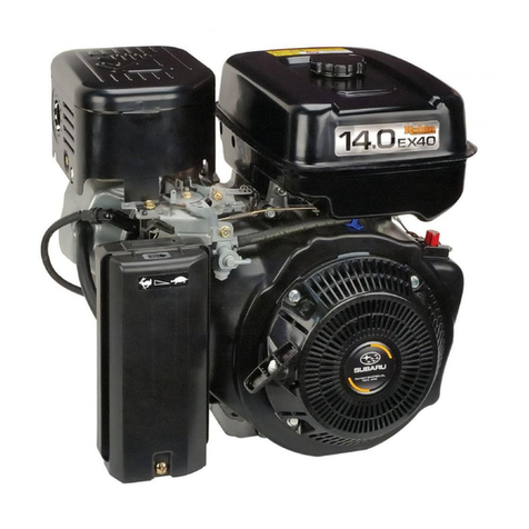
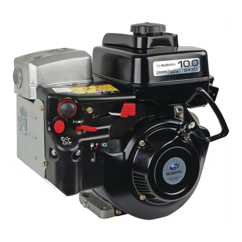
Subaru EH72-2D Operating and installation instructions

SERVICE INFORMATION
ISSUE EMD-EU6947
PRINTED IN JAPAN
February 2010
EH72-2D


CONTENTS
Section Title Page
1. SPECIFICATIONS.1
2. FEATURES .2
3. DISASSEMBLY AND REASSEMBLY.3
3-1..PREPARATIONS.AND.SUGGESTIONS.3
3-2..SPECIAL.TOOLS.3
3-3..DISASSEMBLY.PROCEDURES.(DIFFERENCE). 4
3-4..REASSEMBLY.PROCEDURES.(DIFFERENCE). 6
3-5.BREAK-IN.OPERATION.8
4-1.CARBURETOR.9
4-2.COMPORNENT.PARTS..11
PREFACE
This.manual.covers.the.service.information,.trouble.shooting.procedures.and.so.on.of..
EH72-2.engine
Careful.observance.of.the.instructions.given.herein.will.result.in.better,.safer.and.faster.
service.work
For.more.detailed.instructions.of.disassembling.and.reassembling.procedures,.please..
refer.to.the.service.manual.for.EH63,.64,.65.and.72

-.1.-
1. SPECIFICATIONS
Model EH72-2D
Type Air-Cooled,.4-Stroke,.V-Twin.Cylinder,.Horizontal.PTO.shaft,..
OHV.Gasoline.Engine
Number of Cylinders - Bore
×
Stroke mm (in.)
2.-.84.×.65.(331.×.256)
Displacement ml (cu.in.) 720.(439)
Compression Ratio 87
Continuous Output kW(HP)/r.p.m. 142.(190)./.3600
Maximum Output kW(HP)/r.p.m. Gross.:.187.(250)./.3600
Maximum Torque N•m / r.p.m.
(kgf•m / r.p.m.)
(ft•lb. / r.p.m.)
510./.2800
.(52./.2800)
(376./.2800)
Direction of Rotation Counterclockwise.as.viewed.from.the.PTO.shaft.side
Cooling System Forced.air.cooling
Valve Arrangement Overhead.Valve.(OHV)
Lubrication Full.pressure.type.with.oil.Cooler
Lubricant Automobile.engine.oil.SAE.#20,.#30.or.10W-30;..
Class.SE.or.higher
Capacity of Lubricant L (U.S. gal.) 155.(041)
Carburetor 2-.Barrel.side.draft.type
Fuel Automotive.unleaded.gasoline
Fuel Feed System Diaphragm.Fuel.pump.(Pulse.type)
Ignition System Flywheel.Magneto.(Solid.state)
Spark Plug BPR5ES(NGK).or.BPR4EY(NGK)
Charging Capacity V - A 12.-.15.or.12.-.30.(Option)
Starting System Electric.Starter
Governor System Centrifugal.Flyweight.type
Air cleaner Double.Element.type
Dry Weight kg (lb.)
with out muffler and control box 46.(1013)
with STD muffler and control box 515.(1134)
Dimensions
(L×W×H) mm (in.)
with out muffler and control box 317×477×480.(125×188×189)
with STD muffler and control box 464×499×480.(183×196×189)
* Specifications are subject to change without notice.

-.2.-
2. FEATURES
HIGH OUTPUT, TORQUE AND DURABILITY
720cc.displacement.which.is.the.largest.among.25.horsepower.classed.engines,.produces.high.
torque.from.the.low.speed.range.High.durability.with.less.than.1%.horsepower.drop.after.300.
hours.of.full-throttle.operation
Furthermore,.the.new.generation.of.EH72.(EH72-2).has.achieved.higher.output.by.adopting..
2-.Barrel.Side.draft.carburetor.system,.which.increases.intake.airflow.and.optimally.distributes..
air-fuel.to.each.cylinder,.as.well.as.optimizing.camshaft.profile.and.increasing.compression.ratio
HEAVY DUTY CONSTRUCTON
Reliable.structure.with.pressure.lubrication,.cast.iron.cylinder.sleeve.and.dual.air.cleaner.element.
Also,.heavy.duty.ball.bearing.installed.on.PTO.side
SUPERIOR OIL CONTROL
In.addition.to.the.excellent.oil.control.by.3.pieces.oil.rings,.adoption.of.valve.stem.seal.and.high.
cooling.capability.reduce.oil.consumption.This.enables.longer.oil.maintenance.interval.together.
with.largest.lubrication.oil.capacity.in.this.class
INTAKE MANIFOLD

-.3.-
3. DISASSEMBLY AND REASSEMBLY
3-1 PREPARATIONS AND SUGGESTIONS
(1)..When.disassembling.the.engine,.memorize.the.locations.of.individual.parts.so.that.they.can.
be.reassembled.correctly.If.you.are.uncertain.of.identifying.some.parts,.it.is.suggested.that.
tags.be.attached.to.them
(2)..Have.boxes.ready.to.keep.disassembled.parts.by.group
(3)..To.prevent.losing.and.misplacing,.temporarily.assemble.each.group.of.disassembled.parts
(4)..Carefully.handle.disassembled.parts,.and.clean.them.with.washing.oil.if.necessary
(5)..Use.the.correct.tools.in.the.correct.way
(6)..When.disconnecting.electric.wirings,.be.sure.to.hold.and.disconnect.the.connector.housing
3-2 SPECIAL TOOLS
No.Special.Tool.is.needed.for.disassembling.and.reassembling.the.engine
For.pulling.off.the.flywheel,.universal.type.puller.being.popular.in.the.market.place.as.shown.in.
the.illustration.is.needed.
Description Parts number
Flywheel.puller.for.pulling.off.the.flywheel
Flywheel puller with bolt
228-95001-17

-.4.-
3-3 DISASSEMBLY PROCEDURES (DIFFERENCE)
Step Parts to remove Remarks and procedures Parts Fasteners
8
Chock.control.
lever.and.link
(1) Disconnect the choke rod holder and remove
the choke control rod. (See Fig. 3-1)
(2) Remove the choke knob.
CONTROL BOX
CHOKE
CONTROL ROD
RETURN
SPRING
LINK PIVOT
CHOKE
CONTROL
LINK
CHOKE
KNOB
CLAMP
M5 TAPPING
SCREW
BLOWER HOUSING
M6 FLANGE BOLT
M6 FLANGE
BOLT
STEP 8
Fig.3-1

-.5.-
Step Parts to remove Remarks and procedures Parts Fasteners
9
Carburetor (1)..At.first.remove.fuel.pipe.(See.Fig3-2).
(2)..Remove.the.governor.rod.spring.from.rod.holder.
(3)..Pick.up.the.rod.holder.and.remove.the.governor.rod
(See.Fig3-3)
(4)..Remove.the.nuts,.adapter.and.Carburetor.from.the.
intake.manifold.(See.Fig3-4)
.
.
.
M6.Flange.nut.:.4pcs
FUEL PIPE
GOVERNOR ROD
ROD HOLDER
Turn the rod holder
clockwise to loosen.
VIEW A
Fig.3-2 Fig.3-3
Fig.3-4
SPARK PLUG CAP
GROMMT (PLUG CAP)
#2 CYLINDER SIDE ONLY
AS OPTION #1 CYLINDER SIDE
#1 CYLINDER SIDE
#2 CYLINDER SIDE
A
STEP 9

-.6.-
22) CARBURETOR
Set.gasket.onto.intake.manifold.and.install.
carburetor
M6.Flange.nut.:.4pcs
23) CHOKE CONTROL
Attach.chock.control.link.between.carburetor.
chock.lever.and.chock.control.lever
Attach.governor.spring.between.governor.
lever.and.speed.control.lever
3-4 REASSEMBLY PROCEDURES (DIFFERENCE)
#2 CYLINDER SIDE
SPARK PLUG CAP
GROMMT (PLUG CAP)
#2 CYLINDER SIDE ONLY
GASKET
(CARBURETOR)
CARBURETOR
GASKET
(ADAPTER)
CLEANER
ADAPTER
CHOKE
CONTROL ROD
RETURN
SPRING
LINK PIVOT
CHOKE
CONTROL
LINK
CHOKE
KNOB
CLAMP
M5 TAPPING
SCREW
Tightening torque
166.-.186.N•m
(170.-.190.kgf•cm)
(123.-.137.ft•lb)
The marking down wards.
GASKET (ADAPTER) GASKET (CARBURETOR)

-.7.-
25) SPEED CONTROL LEVER
(1)..Install.speed.control.bracket.onto.intake.
manifold
(2)..Attach.return.spring,.spacer,.friction.
washer,.wing.nut,.etc.to.speed.control.lever.
as.shown.in.the..ilustration
(3)..Connect.governor.spring.to.governor.lever.
and.speed.control.lever
STOP PLATE
SPRING WASHER
SPEED CONTROL
LEVER
M6 FLANGE
BOLT
M6 SELF LOCK
NUT
FRICTION
WASHER
FRICTION
WASHER
BRACKET UNIT,
speed control
E
D
*29(5125
*($5
*29(5125635,1*
$'-867,1*
6&5(:
63(('&21752//(9(5
*29(5125
/(9(5
*29(5125
52'
52'635,1*
&/($1(5$'$37(5
&$5%85(725
)8//23(1
)8//&/26(
/2&.187
+,*+63(('
/2:63(('
$
%
,17$.(0$1,)2/'
/ 5
Fitting location of governor rod and governor spring
50 Hz 60 Hz (STD)
COLOR Silver Gold
POSITION A-3(a)
GOVERNOR ROD ROD HOLDER
Turn the rod holder
counter clockwise
and fix it.
Then hook the rod
spring as shown
on the diagram.
VIEW A
ROD
SPRING
24) GOVERNOR LEVER
Attach.governor.rod.and.rod.spring.between.
governor.lever.and.carburetor.throttle.lever,.
and.insert..the.governor.lever.to.governor.
lever.shaft.Tighten.locking.bolt.temporarily
GOVERNOR
SHAFT
GOVERNOR
LEVER
ROD SPRING
GOVERNOR
ROD ROD HOLDER
THROTTLE LEVER
A
CLEANER ADAPTER
L
R

-.8.-
29) AIR CLEANER and BREATHER PIPE
(1).Connect.breather.pipe.to.air.cleaner.base.
(2)..Set.gasket.onto.cleaner.adapter.and.install.
cleaner.base
(3).Fit.air.cleaner.base.onto.carburetor.
M6.x.12.Flange.bolt.:.3.pcs
(4).Connect.breather.pipe.to.#1.cylinder.head.
(5)..Set.air.cleaner.element.along.with.urethane.
foam.onto.base.
(6).Install.air.cleaner.cover.with.knob
CLEANER BASE CP
GASKET
(CLEANER)
CLEANER
ADAPTER
Tightening torque
68.-.88.N•m
(70.-.90.kgf•cm)
(50.-.65.ft•lb)
3-5 BREAK-IN OPERATION
An.engine.that.has.been.completely.overhauled.by.being.fitted.with.a.new.piston,.rings,.valves.
and.connecting.rod.should.be.thoroughly.BREAK-IN.before.being.put.back.into.service.Good.
bearing.surfaces.and.running.clearances.between.the.various.parts.can.only.be.established.by.
operating.the.engine.under.reduced.speed.and.loads.for.a.short.period.of.time.
While.the.engine.is.being.tested,.check.for.oil.leaks
Make.final.carburetor.adjustment.and.regulate.the.engine.operating.speed.
STEP EH72-2 Engine.speed.(rpm) Time.(minute)
1
No.Load
2500 10
2 3000 10
3 3600 10
4 71kW.(95HP) 3600 30
5 142kW.(190HP) 3600 30

-.9.-
4-1 CARBURETOR
OPERATION AND FUNCTION
[EH72-2]
Main System
Slow System
FUEL NIPPLE
DRAIN
VALVE COMPL,
SOLENOID
JET COML, MAIN(L) JET COML, MAIN(R)
FLOAT
SCREW, THROTTLE
ADJUST
SLOW JET
VALVE, THROTTLE VALVE, CHOKE
MIXTURE
FUEL
AIR
MIXTURE
FUEL
AIR
FUEL
AIR
MIXTURE
FUEL
AIR
MIXTURE
L - R

-.10.-
FLOAT SYSTEM
The.float.system.is.consists.of.a.float.and.a.needle.valve,.and.maintains.a.constant.fuel.level.
during.engine.operation.
The.fuel.flows.from.the.fuel.tank.into.the.float.chamber.through.needle.valve.
When.the.fuel.rises.to.a.specific.level,.the.float.rises,.and.when.its.buoyancy.and.fuel.pressure.are.
balanced,.the.needle.valve.closes.to.shut.off.the.fuel,.thereby.keeping.the.fuel.at.the.predetermined.level.
Air.vent.hole.of.float.chamber.is.provided.around.the.carburetor.air.hone.and.the.fuel.vapor.is.
sucked.into.the.combustion.chamber.This.closed.system.has.unti-dust.feature
PILOT SYSTEM
The.pilot.system.feeds.the.fuel.to.the.engine.during.idling.and.low-speed.operation
The.fuel.is.fed.through.the.main.jet.to.the.pilot.jet,.where.it.is.metered,.and.mixed.with.the.air.
metered.by.the.pilot.air.jet
The.fuel-air.mixture.is.fed.to.the.engine.through.the.pilot.outlet.and.the.by-pass
At.idling.speed,.the.fuel.is.mainly.fed.from.the.pilot.outlet.
MAIN SYSTEM
The.main.system.feeds.the.fuel.to.the.engine.at.medium-and.high-speed.operation
The.fuel.is.metered.by.the.main.jet.and.fed.to.the.main.nozzle.The.air.metered.by.the.main.
air.jet.is.mixed.with.the.fuel.through.the.emulsion.tube,.and.the.mixture.is.atomized.out.of.the.
main.bore.It.is.mixed.again.with.the.air.taken.through.the.air.cleaner.into.an.optimum.fuel-air.
mixture,.which.is.supplied.to.the.engine.
CHOKE
The.choke.is.used.for.easy.start.when.engine.is.cold
When.the.starter.is.operated.with.a.choke.valve.fully.closed,.the.negative.pressure.applied.to.
the.main.nozzle.increases.and.draws.much.fuel.accordingly;.thus.easily.start.up.the.engine.
FUEL CUT VALVE
Fuel.cut.valve,.operated.with.starter.key.switch,.is.equipped.with.main.system.of.carburetor.for.
preventing.engine.running.on.and.after.burning.
When.the.key.switch.is.on,.the.valve.is.activated
.
and.the.plunger.
is.pulled.in.to.open.the.main.jet
When.the.key.switch.is.off,.the.power.source.to.the.valve.is.off.The.plunger.is.pushed.out.by.
the.return.spring.and.stop.the.fuel.flow.of.main.jet.
SOLENOID (for Fuel Cut Off of Carburetor)
.● .Measure.the.resistance.between.the.two.terminals
(Ω.±10%.when.20˚C)
Resistance
32.Ω
.● .
Check.the.operation.of.the.solenoid.independently
Check.operation.at.the.terminals.(Applied.voltage.:.9V)
Faulty.operation..→..Replace.the.solenoid
.● .As.the.solenoid.is.a.constant.pull-in.type.when.the.engine.is.running,.If.the.battery’s.power.is.
low,.it.may.not.work.when.starting.the.engine.because.all.the.available.electricity.is.occupied.
by.the.starting.motor..
.→.Charge.or.replace.the.battery

-.11.-
4-2 COMPORNENT PARTS
..1VALVE,THROTTLE
..2SCREW.SET(VALVE)
..3VALVE,.CHOKE
..4SHAFT.ASSY,CHOKE
..5SHAFT.COMPL,THROTTLE
..6VALVE,.FLOAT
..7PIN,.FLOAT
..8CHAMBER.ASSY,.FLOAT
..9GASKET,.FLOAT.CHAMBER
10FLOAT
11SCREW,.DRAIN
12SPRING,.DRAIN
13SCREW,.THROTTLE.ADJUST
14SPRING(ADJUST.SCREW)
15SCREW
16COLLAR,.CHOKE
17SEAL,CHOKE
18SEAL,THROTTLE
19COLLAR,.THROTTLE
20VALVE.COMPL,SOLENOID
21
GASKET(MATERIAL.:.ALUMINUM)
22O-RING
23GASKET,.SPACER
24SPACER,.CARB
25O-RING
26COVER,.SLOW.PASSAGE
27GASKET,.SLOW.PASSAGE
28SCREW
29JET.COML,MAIN(L)(#132)
30JET.COML,MAIN(R)(#133)
10
21
12
11
8
25
30
29
23
24
15
4
5
14
13
16
17
19
18
1
2
3
9
7
6
22
26
27
28
20
(With locktight)
2(With locktight)
(TIGHTENING TORQUE 1.5~2.5N•m)


SERVICE INFORMATION
ISSUE EMD-EU6947
PRINTED IN JAPAN
February 2010
EH72-2D
Other manuals for EH72-2D
1
Table of contents
Other Subaru Engine manuals

Subaru
Subaru EA190V User manual

Subaru
Subaru Robin Engines SX17 User manual

Subaru
Subaru EH90 User manual

Subaru
Subaru EH72 FI User manual

Subaru
Subaru EH025 User manual

Subaru
Subaru EJ22 Operating instructions

Subaru
Subaru EX13D User manual

Subaru
Subaru EX30D User manual

Subaru
Subaru DY41 User manual

Subaru
Subaru EA175V User manual

Subaru
Subaru 2.2 Liter Engine User manual

Subaru
Subaru EX13 User manual

Subaru
Subaru ER12 User manual

Subaru
Subaru EX series User manual

Subaru
Subaru EA190V User manual

Subaru
Subaru SP-170 User manual

Subaru
Subaru EC01 User manual

Subaru
Subaru EA175V User manual

Subaru
Subaru EA175V User manual

Subaru
Subaru Subaru EX27 User manual