Beward DK103M Instruction Manual

DK103M IP Converter
Installation User Manual

Table of Contents
IP Converter DK103M Installation User Manual
1
Table of Contents
CHAPTER 1. SAFETY MEASURES.................................................................................................2
CHAPTER 2. DESCRIPTION............................................................................................................4
2.1.1. Key Features................................................................................................................4
2.1.2. Package contents.........................................................................................................5
CHAPTER 3. OVERVIEW.................................................................................................................6
3.1. IP CONVERTER ......................................................................................................................6
CHAPTER 4. IP CONVERTER INSTALLATION...............................................................................8
4.1. GENERAL INFORMATION .........................................................................................................8
4.2. INSTALLATION RECOMMENDATIONS.........................................................................................9
4.3. IP CONVERTER MOUNTING ...................................................................................................11
4.4. MEMORY CARD INSTALLATION ..............................................................................................11
4.5.WIRED CONNECTION TO A NETWORK ....................................................................................12
CHAPTER 5. WIRED CONNECTION SETTING.............................................................................13
5.1. DEFINING THE LOCAL NETWORK PARAMETERS FOR WIRED CONNECTION ...............................13
5.1.1. Defining the Local Network Parameters When Using a Dynamic IP Address..............17
5.2. CHANGING THE LOCAL NETWORK PARAMETERS ....................................................................20
5.3. ACCESSING THE IP CONVERTER USING INTERNET EXPLORER ................................................24
5.4. ACCESSING THE IP CONVERTER VIA WEB INTERFACE ............................................................24
5.5. CONFIGURING IP CONVERTER NETWORK SETTINGS VIA WEB INTERFACE................................29
5.6. RESTORING NETWORK SETTINGS OF PC TO THE PREVIOUS VALUES.......................................30
5.7. VERIFYING THE CONNECTION SETTINGS................................................................................33
CHAPTER 6. RECOMMENDATIONS ON SETTING AND OPERATION OF DK103M...................36
6.1. ACOUSTIC ECHO CANCELLATION ..........................................................................................36
6.2. SOUND GAIN AND VOLUME ADJUSTING..................................................................................37
APPENDICES.................................................................................................................................39
APPENDIX A. FACTORY DEFAULTS...............................................................................................39
APPENDIX B. GLOSSARY.............................................................................................................40

Chapter 2. Description
IP Converter DK103M Installation User Manual
2
Chapter 1. Safety Measures
Before using the product.
This product complies with all safety rules. However, improper use of any electric device
can cause fires and severe damage. In order to avoid accidents, please read this Manual carefully
before you start using this door
ATTENTION!
Use accessories specified by the manufacturer only. Use of improper accessories may case device
breakdown.
Follow this Operation Manual.
Do not use or store the IP converter in severe environment:
Avoid extremely low and high temperatures (The operating temperature of this IP
converter is 0°~+50°).
Avoid prolonged exposure to direct sunlight, do not install near water and heat sources.
Do not install near electromagnetic transmitters
Avoid exposure to high vibration.
ATTENTION!
Contact out Service Center in case of malfunction.
In case of:
Smoke or strange smell coming from the device.
Water or foreign matter getting inside the device.
The device getting damaged:
Do the following:
Unplug the power cord and disconnect all other cords from the IP converter.
Contact our Service Center. You can find our contact information on our website:
http://www.beward.ru/.
Chapter 2. Description
IP Converter DK103M Installation User Manual
3
Transportation
Transport the IP converter carefully, using the original box and protective packing
Air flow
In order to avoid overheating, ensure that nothing is blocking the air circulation around the
IP converter!
Cleaning
Use a soft dry cloth to clean the surface of the device. To remove obstinate stains, apply a
small amount of detergent on the cloth, then wipe the surface dry
Do not use volatile solvents (alcohol-containing products, Benzene etc.) to avoid damaging
the device.

Chapter 2. Description
IP Converter DK103M Installation User Manual
4
Chapter 2. Description
BEWARD DK103M IP Converter is designed for organizing IP intercome systems based on
already existing local networks without using any additional equipment (e.g. separate internal
monitors). To start using the device you only have to install the software on your PC or
Smartphone device and set it up. This device is:
Low-cost
Easy to install
Remote Access Supported
Pic. 2.1
DK103M is used for analog-to-digital conversion and managing analog wired matrix
intercom devices. In other words, this device converts analog intercoms into digital intercoms,
while retaining the ability to use the analog monitor. The device allows for establishing video and
audio connection between the Guest and the Client, conducting surveillance of the nearby territory,
control of other devices that are connected to the single-user door station (electronic locks, garage
door openers, light switches, alarm systems etc.) via Ethernet. The device is supported by modern
network technologies, allowing it to be used a part of a complex IP Surveilance system.
DK103M is connected to the network via-T/100BASE-TX Ethernet interface. Its power is
supplied from a DC 12V power source.
The device is even more reliable due to its SD card support that prevents loss of data in
case of network failures.
2.1.1. Key Features
Simultaneous encoding: H.264/H264, Н.264/MJPEG, MJPEG /MJPEG
Built-in web server for viewing and adjusting settings
Built-in player for recorded videos
Build-in microphone and speaker
Power: DC 12 V
Temperature: -0°С~+50°С

Chapter 2. Description
IP Converter DK103M Installation User Manual
5
Supported protocols: TCP/IP, SIP v.2.0, VPN, STUN, HTTP, HTTPS, FTP, SMTP,
DDNS, DHCP, PPPoE, RTP, RTSP, UDP, UPnP, NTP, ONVIF v.2.41
ONVIF v.2.41 support
2.1.2. Package contents
DK103M IP Converter
Self-tapping screws
Wi-Fi antenna (for DKxxxW option)
4G USB modem (for DKxxx4G option)
Terminal block (4 pcs.)
CD with software and documentation
ATTENTION!
Package contents and device specification are subject to change without notice

Chapter 3. Overview
IP Converter DK103M Installation User Manual
6
Chapter 3. Overview
3.1. IP converter
The front view of the IP converter is given below:
Pic. 3.1
1 –Reset button: press this button 3 times with intervals not less than 1 second during 10
seconds to set device settings by default.
2 –Micro SD: slot for mounting a MicroSD memory card (up to 32 Gb).
3 –Ethernet: RJ45 socket for connecting the device to Ethernet
4 –DC 12V: socket for connecting a DC 12V power supply (power equal or more than
12W)
5 –Power indicator: If the device is activated, the red light is ON.
6 –Multiuser Unit socket: used for connecting multi-user wired matrix videointercoms.
7 –Outdoor Unit socket: used for connecting single-user analog videointercoms.
8 –Monitor socket: used for connecting monitors of single-user analog videointercoms.
Prior to using the IP converter, the monitors are connected directly to their analog videointercoms.
9 –RS-485 socket: used for attaching extension controllers
Pic. 3.2

Chapter 3. Overview
IP Converter DK103M Installation User Manual
7
USB:this socket (Pic. 3.2) is used for connecting Huawei E3372 4G modem (purchased
seperately).
Wi-Fi: this socket (Pic. 3.2) is only present for DK103MW models. It is used for connecting
Wi-Fi antennas (included in the DK103MW package). If you are using DK103MW, you must
connect the antenna to transfer data via Wi-Fi.

Chapter 4. IP Converter Installation
IP Converter DK103M Installation User Manual
8
Chapter 4. IP Converter Installation
4.1. General Information
The IP Converter must be connected to a local network (or the Internet) via Ethernet cable .
The device can be connected direcrlt to the PC or via auxiliary network devices (router, switch).
Pic. 4.1
The general instructions and installation recommendations are given below.

Chapter 4. IP Converter Installation
IP Converter DK103M Installation User Manual
9
4.2. Installation Recommendations
This paragraph contains a short list of recommendations necessary for the correct
installation of DK103M.
Recommendations for placement:
The operating temperature range is 0°С to +50°С.
Avoid exposure to direct sunlight and do not place the device near any heat sources.
Avoid exposure to water.
Do not locate the device near any electrical appliances which can be electromagnetic
transmitters.
When installing the device, make sure the cables are laid in a safe and ergonomic way..
Avoid unstable installation, which may allow exposure to high vibration. This may reduce
motion detection performance and image quality in general.
Recommendations for twisted pair cable routing:
In corridors, it is advisable to install electric and feeble-current cables in different
conduits that are disposed on different walls.
Twisted pair and electric cables can be installed in the same conduit using different
sections of the cable that have solid longitudinal partitions with at least 0.25 h of fire
resistance, which are made of non-combustible material and should be positioned in
work areas at distance of 15 meters max. if the electrical power does not exceed 5 kW.
Electric and feeble-current cables should be placed in parallel to each other at distance
of at least 50 mm in different conduits or different sections of conduit. If the electric field
strength from the electric cables exceeds 3 V/m, you should increase the distance
between the electric and feeble-current cables or reduce the electromagnetic noise.
Twisted pair and electric cables should cross each other at right angles.
Unshielded twisted pair cables should be located at distance of at least 125 mm from
fluorescent gas-discharge lamps or from other high-voltage discharge devices.
Unshielded twisted pair cables should be located at distance of at least 1.5 meters from
electromagnetic interference sources that produce electric field strength exceeding 3
V/m.
Switchboards with pinned unshielded twisted pair cables should be located at distance
of at least 3 meters from electromagnetic interference sources that produce electric field
strength exceeding 3 V/m.
Cable runs should be arranged between the points of connection such a way so the
overall cable path length is as short as possible.

Chapter 4. IP Converter Installation
IP Converter DK103M Installation User Manual
10
Minimum cable bending radius is four times the cable diameter (or 1 inch=2.5 cm). It is
also acceptable to install the cable so that the cable bending radius is 2 inches (5 cm).
Maximum length of the entire segment is 100 meters.
Chapter 4. IP Converter Installation
IP Converter DK103M Installation User Manual
11
4.3. IP converter Mounting
Follow the steps below:
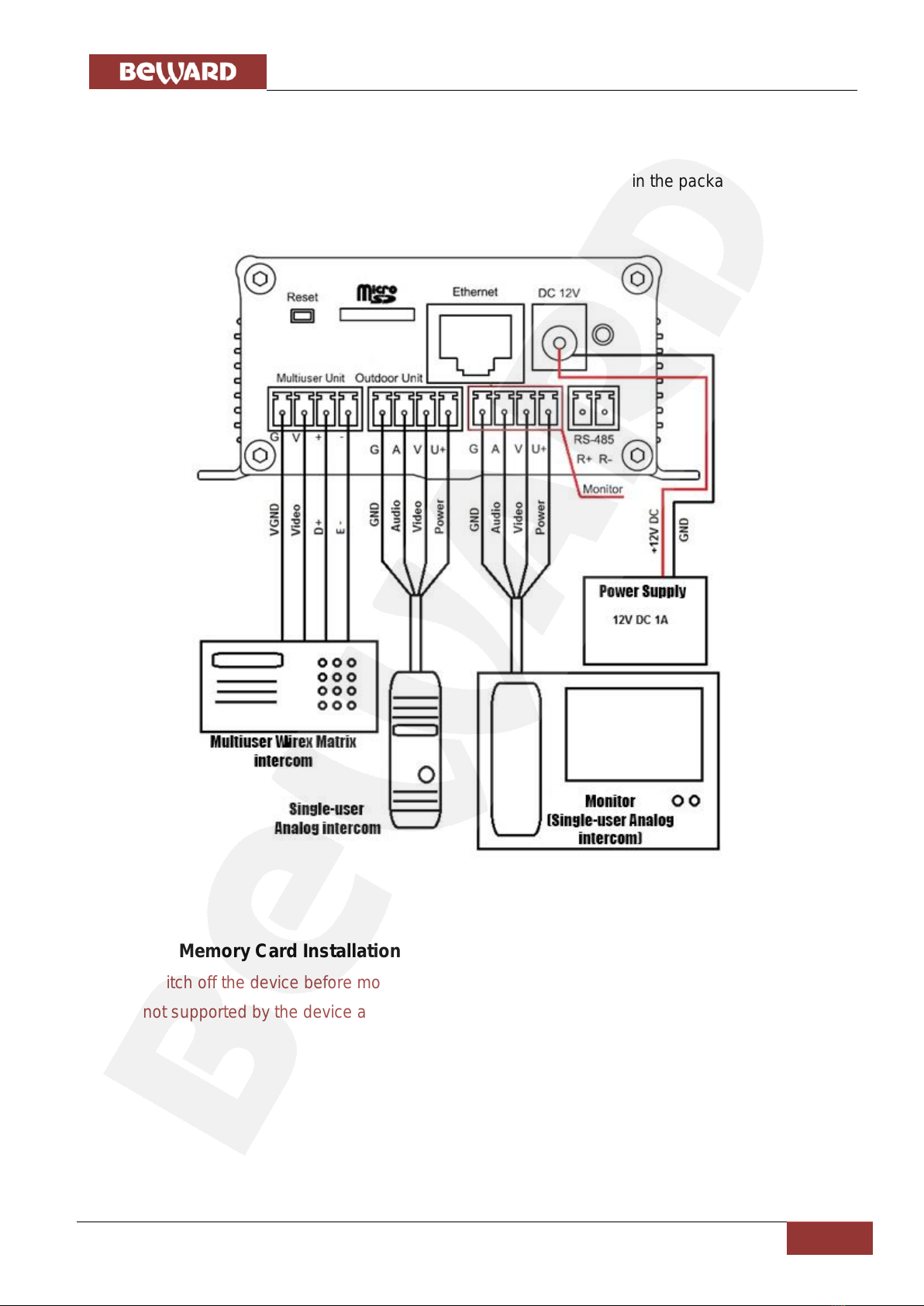
Step 1: Mount the device to a flat surface via 4 screws (included in the package).
See the connection scheme below:
Pic. 4.2
4.4. Memory Card Installation
Switch off the device before mounting/ejecting the memory card. The hot swap of a memory
card is not supported by the device and may damage the equipment or cause a data loss.
Chapter 4. IP Converter Installation
IP Converter DK103M Installation User Manual
12
4.5. Wired Connection to a Network
Connect the device to the local network (to the router’s LAN interface) using a twisted pair
cable with RJ45 connectors.
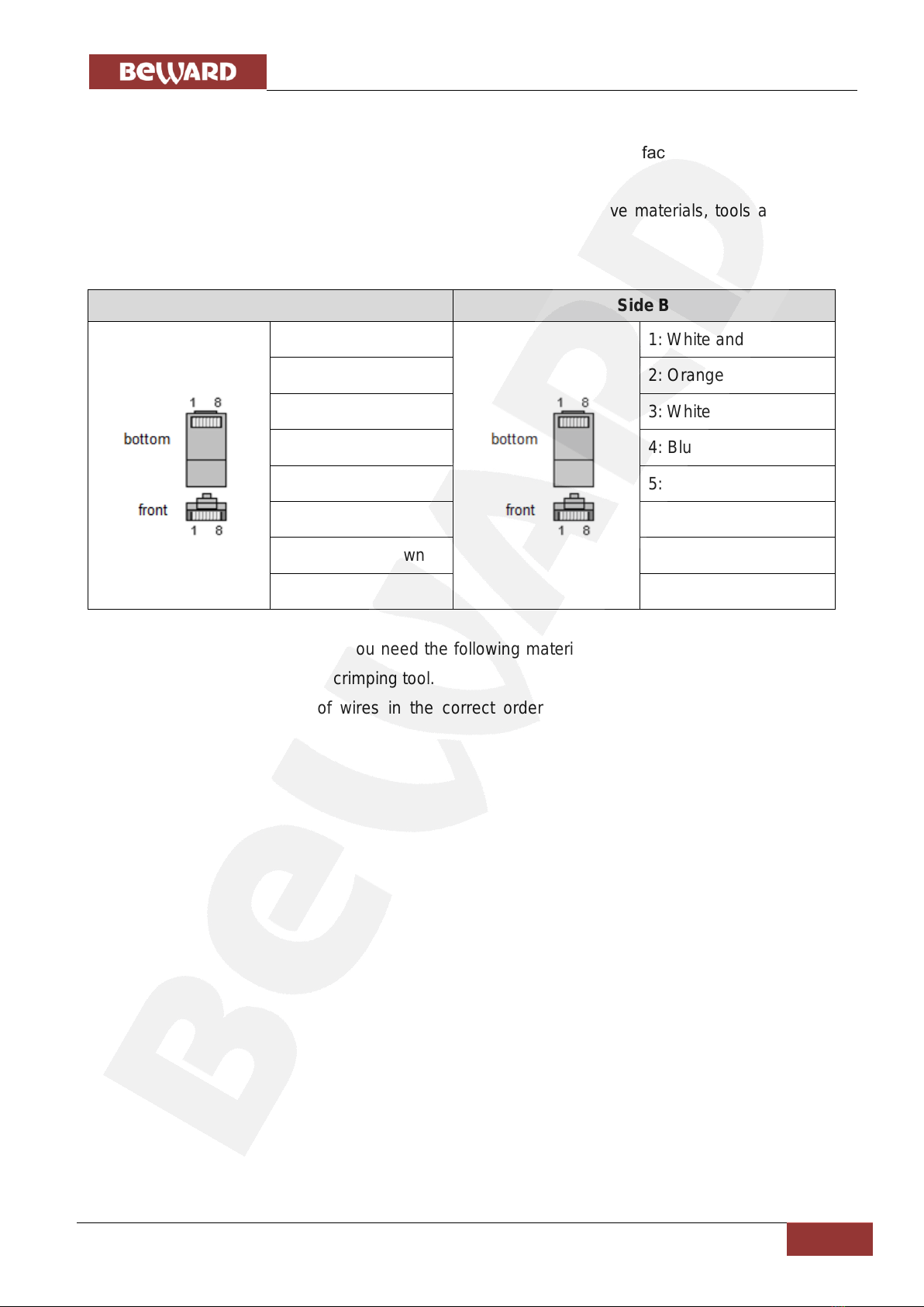
You can purchase the network cable separately or if you have materials, tools and skills,
you can make it by yourself.
A straight RJ-45 cable (UTP category 5e)
Side A
Side B
1: White and orange
1: White and orange
2: Orange
2: Orange
3: White and green
3: White and green
4: Blue
4: Blue
5: White and blue
5: White and blue
6: Green
6: Green
7: White and brown
7: White and brown
8: Brown
8: Brown
To make a network cable, you need the following materials: a UTP category 5e cable, two
RJ-45 connectors and an RJ-45 crimping tool.
Assembling the pairs of wires in the correct order (see the table above) ensures data
transfer speed of 100 Mbps.
Chapter 5. Wired Connection Setting
IP Converter DK103M Installation User Manual
13
Chapter 5. Wired Connection Setting
To make the IP Converter work together with computers, laptops and other devices in your
local network, you need to connect it to the network according to the network parameters. This
chapter explains how to set the network parameters.
NOTE:
The connection establishment process is shown for OS Windows 7 Ultimate. Despite titles of system menus
and options may differ from the titles of system menus and options that appear in other Windows versions,
the procedure of the connection establishment process is universal.
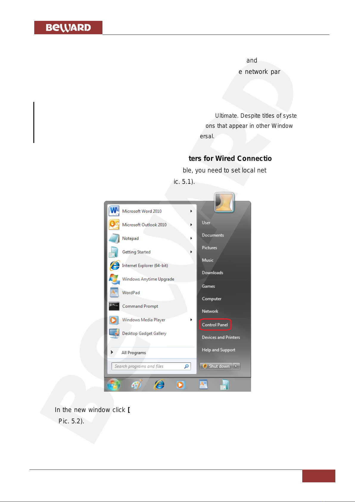
5.1. Defining the Local Network Parameters for Wired Connection
When connecting the device via Ethernet cable, you need to set local network parameters.
To do so, go to Start –Control Panel (Pic. 5.1).
Pic. 5.1
In the new window click [View network status and tasks] in the [Network and Internet]
section (Pic. 5.2).

Chapter 5. Wired Connection Setting
IP Converter DK103M Installation User Manual
14
Pic. 5.2
In the new window click [Local Area Connection] (Pic. 5.3).
Pic. 5.3
NOTE:
If there are several active networks, choose the one that you are going to connect your device to.
Chapter 5. Wired Connection Setting
IP Converter DK103M Installation User Manual
15
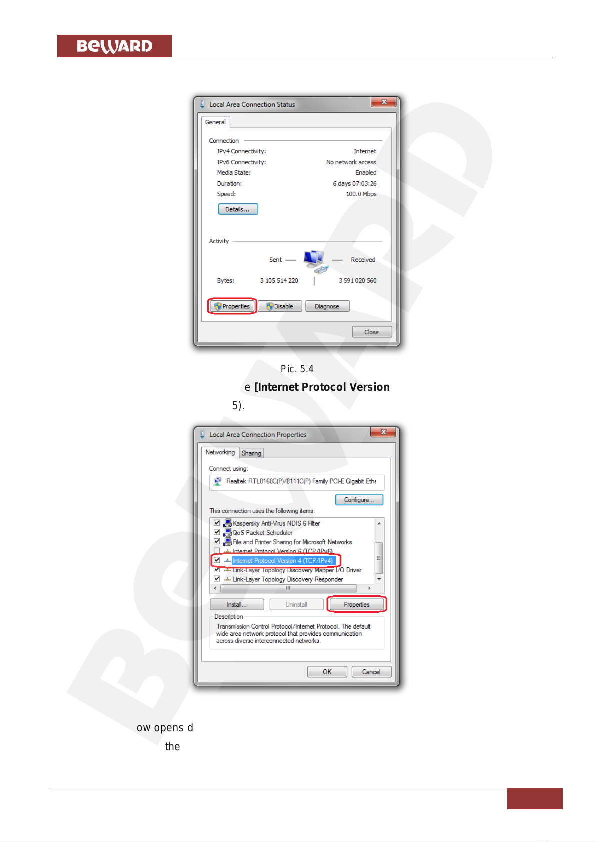
In the new window click the [Properties] button (Pic. 5.4).
Pic. 5.4
In the opened window select the [Internet Protocol Version 4 (TCP/IPv4)] menu item and
click the [Properties] button (Pic. 5.5).
Pic. 5.5
The window opens displaying information about the network connection settings. There are
two ways to configure the IP address:
Chapter 5. Wired Connection Setting
IP Converter DK103M Installation User Manual
16
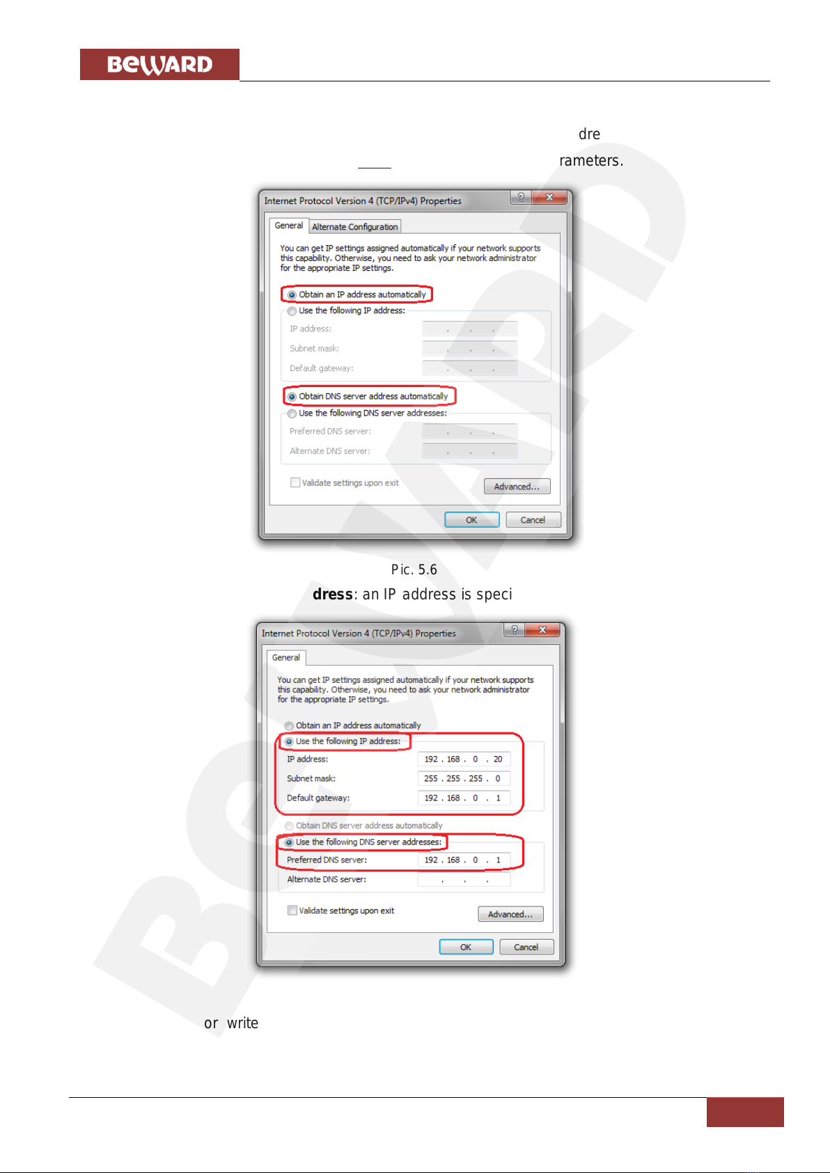
1. Obtain an IP address automatically: select this option to obtain the IP address
automatically from a DHCP-server on your network (Pic. 5.6). If the IP address is assigned to your
computer automatically, go to paragraph 5.1.1 to define the network parameters.
Pic. 5.6
2. Use the following IP address: an IP address is specified manually (Pic. 5.7).
Pic. 5.7
Memorize or write down the following parameters: IP address, Subnet mask, Default
gateway, DNS server.

Chapter 5. Wired Connection Setting
IP Converter DK103M Installation User Manual
17
ATTENTION!
If you forget the network parameters it is impossible to return the computer’s network settings to their
original state and to connect it to a local network or the Internet after configuring the device.
5.1.1. Defining the Local Network Parameters When Using a Dynamic IP Address
NOTE:
This paragraph explains how to define the local network parameters if an IP address is assigned to your
computer automatically (by DHCP-server).
Connect a computer (laptop) to your local network using a network cable and wait till the
connection process completing.
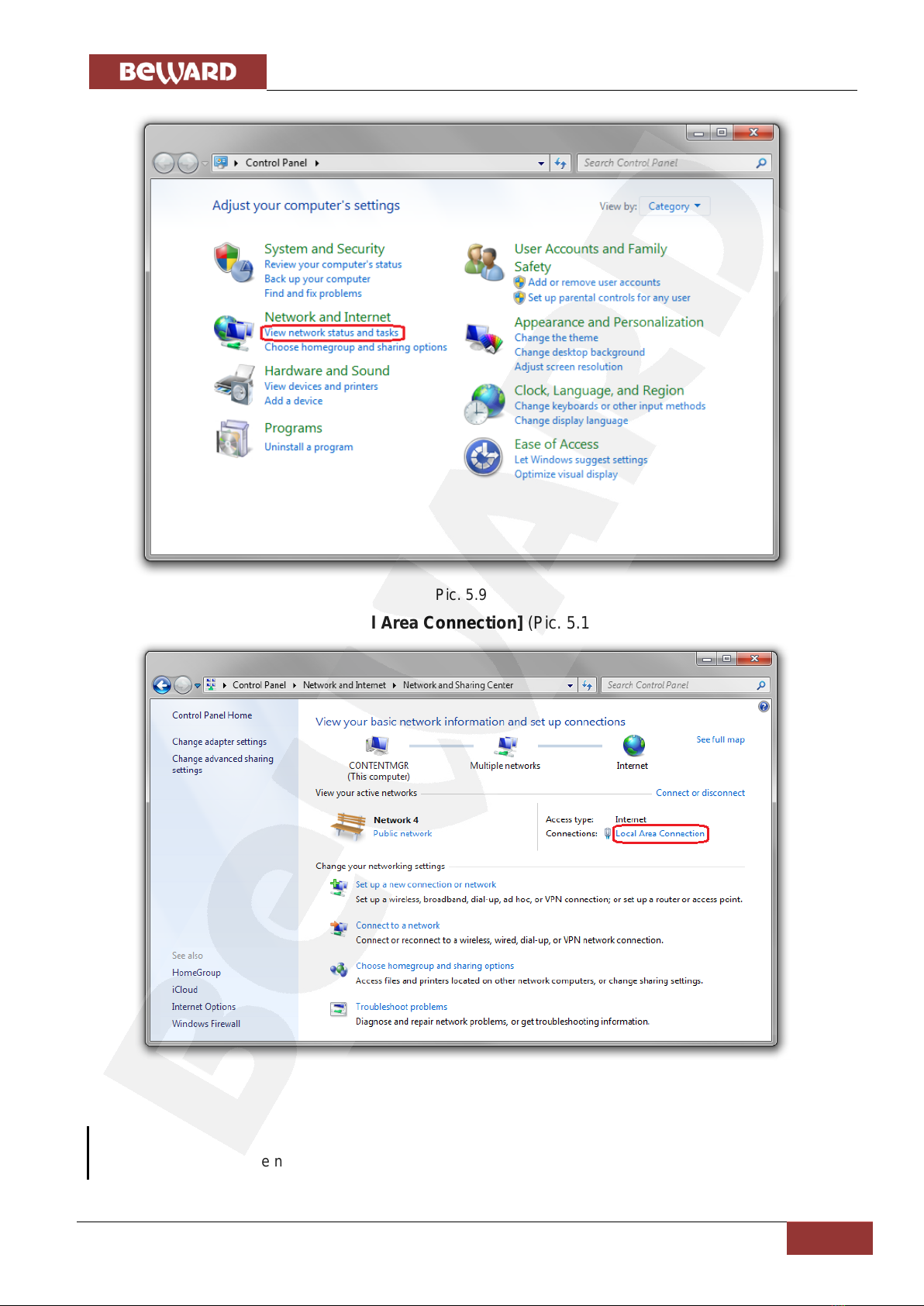
To define the local network settings, go to Start –Control Panel (Pic. 5.8).
Pic. 5.8
In the opened window click [View network status and tasks] in the [Network and
Internet] section (Pic. 5.9).
Chapter 5. Wired Connection Setting
IP Converter DK103M Installation User Manual
18
Pic. 5.9
In the new window click [Local Area Connection] (Pic. 5.10).
Pic. 5.10
NOTE:
If there are several active networks, choose the one that you are going to connect your device to.

Chapter 5. Wired Connection Setting
IP Converter DK103M Installation User Manual
19
In the opened window click the [Details] button (Pic. 5.11).
Pic. 5.11
In the opened window you can see the current network connection details (Pic. 5.12).
Pic. 5.12
Other manuals for DK103M
1
Table of contents
Other Beward Media Converter manuals


