Beyerdynamic CA 4146 User manual

CA 4146
Netzgerät
Power Supply Unit
Alimentation
BEDIENUNGSANLEITUNG
OPERATING INSTRUCTIONS
NOTICE D’UTILISATION

CA 4146 – Contents 15
english
1. Safety information . . . . . . . . . . . . . . . . . . . . . . . . . . . . . . . . . . . . . . . . . . . . . . . . . . . . . . . . . . . . . . . . . . . . . . . . . . . . 16
2. Controls and indicators . . . . . . . . . . . . . . . . . . . . . . . . . . . . . . . . . . . . . . . . . . . . . . . . . . . . . . . . . . . . . . . . . . . . . . . . 17
3. Installation NetRateBus. . . . . . . . . . . . . . . . . . . . . . . . . . . . . . . . . . . . . . . . . . . . . . . . . . . . . . . . . . . . . . . . . . . . . . . . . 17
4. Connections. . . . . . . . . . . . . . . . . . . . . . . . . . . . . . . . . . . . . . . . . . . . . . . . . . . . . . . . . . . . . . . . . . . . . . . . . . . . . . . . . 18
4.1 MCS-D 200 control unit – CA 4146 power supply unit. . . . . . . . . . . . . . . . . . . . . . . . . . . . . . . . . . . . . . . . . . . . 18
4.2 Microphone units – CA 4146 power supply unit . . . . . . . . . . . . . . . . . . . . . . . . . . . . . . . . . . . . . . . . . . . . . . . . 18
4.3 How to turn on the CA 4146 power supply unit . . . . . . . . . . . . . . . . . . . . . . . . . . . . . . . . . . . . . . . . . . . . . . . . 18
4.4 Bus-Power out . . . . . . . . . . . . . . . . . . . . . . . . . . . . . . . . . . . . . . . . . . . . . . . . . . . . . . . . . . . . . . . . . . . . . . . . . . 18
4.5 Redundant Operation with CA 4146 . . . . . . . . . . . . . . . . . . . . . . . . . . . . . . . . . . . . . . . . . . . . . . . . . . . . . . . . . 18
5. Technical specifications. . . . . . . . . . . . . . . . . . . . . . . . . . . . . . . . . . . . . . . . . . . . . . . . . . . . . . . . . . . . . . . . . . . . . . . . . 19
6. Optional accessories. . . . . . . . . . . . . . . . . . . . . . . . . . . . . . . . . . . . . . . . . . . . . . . . . . . . . . . . . . . . . . . . . . . . . . . . . . . 19
7. Examples . . . . . . . . . . . . . . . . . . . . . . . . . . . . . . . . . . . . . . . . . . . . . . . . . . . . . . . . . . . . . . . . . . . . . . . . . . . . . . . . . . . 20
EC-Declaration of Conformity . . . . . . . . . . . . . . . . . . . . . . . . . . . . . . . . . . . . . . . . . . . . . . . . . . . . . . . . . . . . . . . . . . . . . . . 38

CA 4146 – Safety Information 16
Thank you for selecting the CA 4146 power supply unit from beyerdynamic. Please take some time to read through this manual carefully
before using this product.
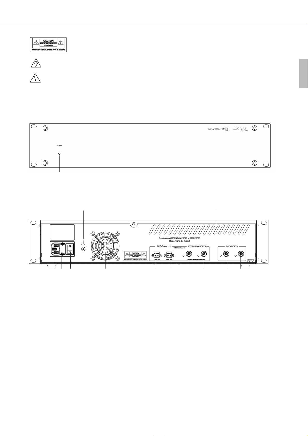
The CA 4146 power supply unit is used when more than 30 devices are to be used with the MCS-D 200 control unit. The CA 4146 power
supply unit can be used as a desktop device or mounted into a 19" rack.
One CA 4146 power supply unit can power up to 45 devices (e.g. microphone units, adaptors). Please note this is only a theoretical value.
The actual number of devices (e.g. microphone units, adaptors) also depends on the cable length.
1. Safety information
General
• READ these instructions.
• KEEP these instructions.
• HEED all warnings and follow all instructions.
Exemption from liability
• beyerdynamic GmbH & Co. KG will not be liable if any damage, injury or accident occurs due to negligent, incorrect or inappropriate
operation of the product.
Location
• The equipment must be set up so that the mains switch, mains plug and all connection on the rear of the device are easily accessible.
• If you transport the equipment to another location take care to ensure that it is adequately secured and can never be damaged by being
dropped or by impacts on the equipment.
Fire hazard
• Never place naked flames near the equipment.
Humidity / heat sources
• Never expose the equipment to rain or a high level of humidity. For this reason do not install it in the immediate vicinity of swimming
pools, showers, damp basement rooms or other areas with unusually high atmospheric humidity.
• Never place objects containing liquid (e.g. vases or drinking glasses) on the equipment. Liquids in the equipment could cause a short circuit.
• Do not install near any heat sources such as radiators, heat registers, stoves or other apparatus (including amplifiers) that produce heat.
Ventilation
• This equipment needs adequate ventilation. Do not cover ventilation grilles. If the heat it generates cannot be dissipated, the equipment
could be damaged or flammable materials in its immediate vicinity could be ignited. Take care to ensure that the air can circulate freely
through the ventilation grilles and keep flammable materials away.
• Do not insert objects into the ventilation grilles or other openings. You could damage the equipment and/or injure yourself.
Connection
• The equipment must be connected to a mains socket that has an earth contact.
• Protect the power cord from being walked on or pinched particularly at plugs, convenience receptacles, and the point where they exit from
the apparatus.
• Lay all connection cables so that they do not present a trip hazard.
• Whenever working on the equipment switch off all inputs and outputs to the power supply.
• Check whether the connection figures comply with the existing mains supply. Serious damage could occur due to connecting the system
to the wrong power supply. An incorrect mains voltage could damage the equipment or cause an electric shock.
• Unplug the device during lightning storms or when unused for long periods of time.
• If the equipment causes a blown fuse or a short circuit, disconnect it from the mains and have it checked and repaired.
• Do not hold the mains cable with wet hands. There must be no water or dust on the contact pins. In both cases you could receive an
electric shock.
• The mains cable must be firmly connected. If it is loose there is a fire hazard.
• Always pull out the mains cable from the mains and/or from the equipment by the plug – never by the cable. The cable could be damaged
and cause an electric shock or fire.
• Do not use the equipment if the mains plug is damaged.
• If you connect defective or unsuitable accessories, the equipment could be damaged. Only use connection cables available from or
recommended by beyerdynamic. If you use cables you have made up yourself, all claim to warranty is null and void.
Maintenance
• Only clean the equipment with a slightly damp or dry cloth. Never use solvents as these damage the surface.
Trouble shooting and servicing
• Do not open the equipment without authorisation. You could receive an electric shock. Leave all service work to authorised expert personnel.
• Refer all servicing to qualified service personnel.

CA 4146 – Controls and Indicators 17
english
The label shown on the left is attached to back of the unit. The symbols on
this label have the following meaning:
This symbol indicates that dangerous voltage constituting a risk of electric shock is present within this unit.
This symbol indicates that there are important operating and maintenance instructions in the literature accompanying this unit.
Safety symbols
2. Controls and indicators
Front view
Rear view
Mains connector
Fuse holder
Power switch
Ventilation outlet (Do not cover to provide unrestricted circulation.)
NetRateBus sockets, BUS-Power out, 48 V, 6 A max.
EXTENSION PORTS to connect microphone units such as MCS-D 202, Revoluto MCS-D 3173/3171 etc.
DATA PORTS to connect the MCS-D 200 control unit, CA 4146 power supply unit, CA 4522/44/66 digital/analogue interface
Ventilation slots (Do not cover to provide unrestricted circulation.)
Functional earth (avoid connection to earth wire)
3. Installation NetRateBus
• Devices, which are connected to the 6-pin connectors of the NetRateBus (DATA PORT and EXTENSION PORT ), are supplied with data
and current. Each chain may only be powered by one power supply unit (MCS-D 200 control unit or power supply unit of the CA 41xx
series). This is the reason why the CA 4146 power supply unit provides active and passive connections. The description “active” or
“passive” only refers to the power supply. Independing on the applied connector, the data are allocated to all connectors.
• The two DATA PORT sockets are passive connectors, i.e. the connected consumers (e.g. microphone units or adapters) are not
powered by the internal power pack of the CA 4146.
• The two EXTENSION PORTS are active connectors, i.e. the connected consumers (e.g. microphone units or adapters) are powered by
the internal power pack of the CA 4146.
• Within one chain only one active EXTENSION PORT of a power supply unit (MCS-D 200 control unit or power supply units of the CA 41xx
series) may be connected. The ring cabling is allowed when it starts and ends at the EXTENSION PORTs of the same CA 4146 power supply
unit. Refer also to chapter 7. “Examples”.
Power LED. LED illuminates green: device is turned on and ready for use

CA 4146 – Connections 18
4. Connections
4.1 MCS-D 200 control unit – CA 4146 power supply unit
• The MCS-D 200 control unit is connected to the DATA PORT of the CA 4146 power supply unit. Refer also to chapter 7. “Examples”.
Warning: Devices connected to the DATA PORT such as adapters or digital/analogue interfaces are powered by the MCS-D 200 control
unit and have to be considered for its power calculation.
4.2 Microphone units – CA 4146 power supply unit
• Connect microphone units, digital/analogue interfaces to the EXTENSION PORTS .
• Each device, which is connected to one of the EXTENSION PORTS , is powered by the CA 4146 power supply unit when the MCS-D 200
control unit and the power supply unit are switched on. The illuminated Power LED displays the power output of the power supply unit.
4.3 How to turn on the CA 4146 power supply unit
• Check all cables before turning on.
• We recommend turning on the devices in the following order.
1. Turn on all power supply units. The Power LED displays the operational status.
2. Then turn on the MCS-D 200 control unit. The Power LED of the MCS-D 200 control unit will illuminate.
4.4 BUS-Power out
• In special installations it may be necessary to guide the power supply of the microphone units separately from the NetRateBus cable. For
this kind of application there are the two BUS-Power out connectors.
• The sum of the currents which are drawn from the BUS-Power out connectors and the EXTENSION PORTs should not exceed 6 A.
4.5 Redundant Operation with CA 4146
• Use two CA 4146 power supply units in one MCS-D 200 system for redundant operation. Should one CA 4146 power supply unit fail, the
system will still operate without any interruption. At maximum you can connect 45 microphone units.
• Keep the subsequent set-up to achieve the desired redundancy.
MCS-D 200 control unit
1. CA 4146 power supply unit
2. CA 4146 power supply unit
MCS-D 31xx MCS-D 31xx MCS-D 31xx
max. 45 microphone units in the circle

CA 4146 – Optional Accessories 19
english
5. Technical specifications
Mains voltage. . . . . . . . . . . . . . . . . . . . . . . . . . . . . . . . . . 100 - 240 V AC 47 - 63 Hz
Fuse . . . . . . . . . . . . . . . . . . . . . . . . . . . . . . . . . . . . . . . . . 6.3 AT (H)
Power consumption . . . . . . . . . . . . . . . . . . . . . . . . . . . . . 330 W
Output current . . . . . . . . . . . . . . . . . . . . . . . . . . . . . . . . . max. 6 A DC
Temperature range . . . . . . . . . . . . . . . . . . . . . . . . . . . . . . 0 °C - +40 °C (humidity < 90%)
Dimensions (W x H x D) . . . . . . . . . . . . . . . . . . . . . . . . . . 19", 2 U (440 x 88 x 310 mm)
System connections . . . . . . . . . . . . . . . . . . . . . . . . . . . . . 2 x push pull, 6-pin, type Lemo/ODU
Extension connections . . . . . . . . . . . . . . . . . . . . . . . . . . . 2 x push pull, 6-pin, type Lemo/ODU
Weight. . . . . . . . . . . . . . . . . . . . . . . . . . . . . . . . . . . . . . . 5200 g
6. Optional accessories
CA 4302 NetRateBus cable, push-pull connectors, 2 m long . . . . . . . . . . . . . . . . . . . . . . . . . . . . . . . . . . . . . . . . . . . . Order # 483.361
CA 4305 same as above, but 5 m long . . . . . . . . . . . . . . . . . . . . . . . . . . . . . . . . . . . . . . . . . . . . . . . . . . . . . . . . . . . . Order # 483.370
CA 4310 same as above, but 10 m long . . . . . . . . . . . . . . . . . . . . . . . . . . . . . . . . . . . . . . . . . . . . . . . . . . . . . . . . . . . Order # 483.389
CA 4320 same as above, but 20 m long . . . . . . . . . . . . . . . . . . . . . . . . . . . . . . . . . . . . . . . . . . . . . . . . . . . . . . . . . . . Order # 483.397
CA 4300 NetRateBus cable, sold per metre . . . . . . . . . . . . . . . . . . . . . . . . . . . . . . . . . . . . . . . . . . . . . . . . . . . . . . . . . Order # 483.354
CA 4222 Digital repeater, DC connector for NetRateBus conference network, 2 push-pull connectors . . . . . . . . . . . . . Order # 483.265
CA 4223 Digital T-adapter, DC connector for NetRateBus conference network, 3 push-pull connectors . . . . . . . . . . . . Order # 483.273
CA 4224 Digital X-adapter, DC connector for NetRateBus conference network, 4 push-pull connectors. . . . . . . . . . . . Order # 483.281

CA 4146 – Examples 20
7. Examples
Inserting devices at any location
Devices such as microphone stations, interpreter stations and digital / analogue interfaces are looped in anywhere in the system.
Additional power supply units for chains
MCS-D 200 control unit (1 integrated power supply = 2 A) . . . . . . . . . . . . . . . . . . for approx. 15 devices
MCS-D 200 control unit option A (2 intergrated power supplies = 4 A). . . . . . . . . . for approx. 30 devices
To expand the system:
CA 4146 power supply unit (6 A) . . . . . . . . . . . . . . . . . . . . . . . . . . . . . . . . . . . . . . for approx. 45 devices
Connect the control unit and the power supply unit with each other via the DATA PORTS.
Connect all devices consuming power such as microphone units, interpreter stations, digital / analogue interfaces and adapters to the
EXTENSION PORTS.
MCS-D 200 control unit
OK
CA 4146 power supply unit
OK
MCS-D 200 control unit
CA 4146 power supply unit
more
microphone units
more
microphone units
more
microphone units
more
microphone units
more
microphone units
more
microphone units

CA 4146 – Examples 21
english
Additional power supply units when the microphone units are set up in a loop
With redundancy i.e. powering the microphone stations on both sides, any cable of the loop can be removed during operation without
interrupting the meeting. All microphone stations are then powered on one side. In this way a microphone station can be replaced during
operation for example.
A condition for redundancy is that all cable lengths had been selected in a way that a single-sided powering could cover the power
requirement.
Setup of the microphone stations in a loop
With redundancy i.e. powering the microphone stations on both sides, any cable of the loop can be removed during operation without
interrupting the meeting. All microphone stations are then powered on one side. In this way a microphone station can be replaced during
operation for example.
A condition for redundancy is that all cable lengths had been selected in a way that a single-sided powering could cover the power
requirement.
OK
MCS-D 200 control unit
CA 4146 power supply unit
OK
MCS-D 200 control unit
CA 4146 power supply unit

CA 4146 – Examples 22
Set up the microphone stations as a chain or in a loop.
The microphone stations are connected to the Extension Ports of the power supply units as a chain or in a loop.
OK
MCS-D 200 control unit
CA 4146 power supply unit
more microphone units

CA 4146 – Examples 23
english
Do not link chains, which are powered by different power supply units!
Warning:
Never link chains, which are powered by different power supply units. This could lead to an overload of the cable and cause short circuits
and cable fire.
MCS-D 200 control unit
CA 4146 power supply unit
NOT ALLOWED!
Possible overload of the cable!
more microphone units

CA 4146 – Examples 24
How to connect a power supply unit to the Extension Port
Note:
In this setup the microphone units connected to the power supply unit no. 3 only work when all power supply units are turned on.
MCS-D 200 control unit
1. CA 4146 power supply unit
2.CA 4146 power supply unit
3. CA 4146 power supply unit
more microphone units

CA 4146 – Examples 25
english
Setup of the system with microphone stations and interpreter stations
1 MCS-D 200 control unit (push-pull socket)
2 MCS-D 3171 delegate microphone unit with push-pull sockets, language selector, voting buttons and display
2a MCS-D 3173 chairman microphone unit with PRIORITY and CLEAR buttons (configuration via MCS-D 200 control unit),
push-pull sockets, language selector, voting buttons and display
3 MCS-D 202 interpreter station, headset (or microphone and headphone)
4 CA 4146 power supply unit, 6 A
5 CA 4566 Digital / analogue interface (6 in / 6 out)
6 E.g. external transmitter for wireless transmisson
7 Cable
8 CA 4302 conference cable (2 m, push-pull)
9 CA 4213 adapter (T-adapter)
1
6
7
5
4
8
3
9
2a
2

38
EC-DECLARATION
OF CONFORMITY
Application of
Council directive: 2004/108/EC
Electromagnetic Compatibility
Standards to which
Conformity is declared: EN 61 000-6-2 Immunity
EN 61 000-6-3 Emission
Manufacturer’s Name: beyerdynamic GmbH & Co. KG
Manufacturer’s Address: Theresienstrasse 8, 74072 Heilbronn, Germany
Type of Equipment: Conference & Discussion System
Model Numbers: CA 4146
I, the undersigned, as an employee of beyerdynamic, hereby declare that the equipment specified conforms to the above
Directive and Standards.
Manufacturer’s Signature:
Full Name: Ulrich Roth
Date: 1st January 2008
Position: Director of R&D

D4/BA CA 4146 (04.10)/Hoh./601.942 •
Änderungen und Irrtümer vorbehalten • Subject to change without notice. • Illustrations non contractuelles.
Sous réserve de modifications. • Printed in Germany
beyerdynamic GmbH & Co. KG
Theresienstr. 8 | 74072 Heilbronn – Germany
Tel. +49 (0) 7131 / 617 - 0 | Fax +49 (0) 7131 / 617 - 224
Weitere Vertriebspartner weltweit finden Sie unter www.beyerdynamic.de
For further distributors worldwide, please go to www.beyerdynamic.com
Table of contents
Popular Power Supply manuals by other brands

MGE UPS Systems
MGE UPS Systems 18/280 kVA Installation and user manual

Vertiv
Vertiv NetSure 5100 Series user manual

ABB
ABB ODPSE230C Installation and operating instructions

TDK-Lambda
TDK-Lambda LC1202 instruction manual

Ingenico
Ingenico iCT 200 Series quick start guide

QYSEA
QYSEA FIFISH quick start guide