Newport Oriel OPS-Q250 User manual
s
OPS-Q250, OPS-Q1000
Oriel® Quartz Tungsten
Halogen Lamp Power
Supplies
User's Manual
Family of Brands –ILX Lightw av e® •New Focus™ •Ophir® •Corion •Richardson Gratings™ •Spectra-Physics®
90074225MOPS-Q,RevB

90074225 MOPS-Q QTH Lamp Power Supplies
Page 2
1 GENERAL INFORMATION ......................................................................................... 5
1.2 GENERAL
WARNINGS
.............................................................................................................
6
1.3 ELECTRICAL
HAZARDS...........................................................................................................
7
1.4 FIRE
HAZARDS
.........................................................................................................................
7
1.5 LAMP
HANDLING
......................................................................................................................
7
1.6 LIGHT HAZARDS
......................................................................................................................
7
2 INTRODUCTION.......................................................................................................... 8
2.1
DESCRIPTION/FEATURES ......................................................................................................
8
2.2 DIMENSIONS
............................................................................................................................
9
2.3 QTH LAMP
COMPATIBILITY ..................................................................................................
10
3 SYSTEM SETUP........................................................................................................ 11
3.1 ITEMS INCLUDEDWITH
SYSTEM.........................................................................................
11
3.2
UNPACKING
............................................................................................................................
11
3.3 CHOOSINGA
LOCATION.......................................................................................................
11
3.4 POWERSUPPLY
CONNECTIONS.........................................................................................
12
3.4.1. Front Panel Controls/Connections ................................................. 12
3.4.2. Rear Panel Controls/Connections.................................................. 13
3.5 INITIAL START-UP
SCREEN
..................................................................................................
17
4 QUICK START GUIDE .............................................................................................. 18
4.1 SETTING LAMP
PARAMETERS
.............................................................................................
18
4.2 TURNING THE LAMP ON/OFF
...........................................................................................
18
4.3 LIGHT INTENSITY CONTROL
............................................................................................
19
5 OPERATING MODES................................................................................................ 20
5.1 POWER
MODE
........................................................................................................................
20
5.2 CURRENT
MODE
....................................................................................................................
20
5.3 INTENSITY
MODE...................................................................................................................
20
5.3.1. Dosed Mode .................................................................................. 20
6 POWER AND CURRENT OPERATION MODES...................................................... 21
6.1 POWEROPERATIONMODE
.................................................................................................
21
6.2 CURRENTOPERATIONMODE
.............................................................................................
23
7 FIRMWARE AND MODEL INFORMATION.............................................................. 24
7.1 UPDATINGTHE
FIRMWARE..................................................................................................
24
8 INTERLOCK CABLES/CONNECTIONS TO LAMP HOUSINGS.............................. 26
8.1 CONNECTION TO A Q SERIESTYPE
HOUSING
.................................................................
27
8.2 CONNECTION TO A RESEARCHLAMP
HOUSING..............................................................
28
9 DETECTOR THERMOELECTRIC COOLING ........................................................... 29
10 INTENSITY OPERATION MODE............................................................................. 32
10.1IDLE
FUNCTION....................................................................................................................
38
11 SHUTTER CONTROLLER ..................................................................................... 39
11.1SHUTTER
STATUS
...............................................................................................................
40
11.2 MANUAL SHUTTERMODE
.................................................................................................
40
11.3TTL SHUTTER CONNECTION
.............................................................................................
41
11.4TTL SIGNAL
POLARITY........................................................................................................
42
11.5TIMEDSHUTTER
MODE
......................................................................................................
43
11.6DOSED SHUTTERMODE
....................................................................................................
45
11.7EXTERNAL SHUTTER CONTROL
METHODS ....................................................................
47

90074225 MOPS-Q QTH Lamp Power Supplies
Page 3
12 AUDIO WARNING ................................................................................................... 48
12.1AUDIOWARNING
SETUP ....................................................................................................
48
13 MEMORY................................................................................................................. 49
14 SAVING SETTINGS................................................................................................. 50
15 MAINTENANCE ....................................................................................................... 51
15.1POWERSUPPLY
CLEANING
...............................................................................................
51
15.2LAMP CARE AND
HANDLING
..............................................................................................
52
16 LAMP LIFETIME AND REPLACEMENT................................................................. 52
17 DISPLAYING TOTAL LAMP HOURS ..................................................................... 53
17.1RESETTINGTOTAL LAMP
HOURS
.....................................................................................
53
18 OPS-Q SERIES OVERVIEW ................................................................................... 55
19 TROUBLESHOOTING............................................................................................. 56
EU DECLARATION OF CONFORMITY....................................................................... 59
APPENDIX A: COMPUTER CONTROL...................................................................... 60
COMMAND SET........................................................................................................... 61
WARRANTY AND SERVICE ........................................................................................ 67
CONTACTING ORIEL INSTRUMENTS........................................................................ 67
REQUEST FOR ASSISTANCE / SERVICE.................................................................. 68
REPAIR SERVICE........................................................................................................ 68
NON-WARRANTY REPAIR.......................................................................................... 68
WARRANTY REPAIR................................................................................................... 69
LOANER / DEMO MATERIAL ...................................................................................... 70
LIST OF FIGURES
Figure 1 Dimensionaldrawingof the OPS Series PowerSupplies.
.............................................................
9
Figure 2 OPS-Q Power SupplyFront Panel
Connections. .........................................................................
12
Figure 3 OPS-Q Power SupplyRearPanel
Connections
...........................................................................
13
Figure 4 The LCDdisplayof the OPS-Q Model PowerSupply.
.................................................................
17
Figure 5 USB ConnectorforFirmware
Updates. ........................................................................................
25
Figure 6 The LCDscreen image displayedduring firmwareand LCD GUI interface
updates. ..................
26
Figure 7 The output connectoron the rear panel ofthe OPS-Q250/OPS-Q1000Power Supplyfor interface
withOriel Lamp Housing. The 70050 (Black)Lamp Housing InterconnectionCable is also shown.
.........................................................................................................................................................
27
Figure 8 The Interlock Open and warning symbol indicatorof the power supply indicates a cable is
disconnectedand/or the lamp housing is open.
.........................................................................................
29
Figure 9 The LIK-LMPLight IntensityController Kit couplesto the Series Q orResearchLamp Housing
chosen by the user and includes the necessarycables to connect the LIK-LMPto the OPS-QPower
Supply.
........................................................................................................................................................
29
Figure 10 Setting the TE Cooler
Temperature
............................................................................................
30
Figure 11 Exploded viewof 71582 mountingto a Q Series Housing using the 68954 Adapter
Kit............
33
Figure 12 Exploded viewof 71582 mountingto a ResearchLamp Housing using the 68952 Adapter Kit.34

90074225 MOPS-Q QTH Lamp Power Supplies
Page 4
Figure 13 The DETECTORINPUTand TE COOLER output ports are for direct use of the LIK-LMP
with
the
OPS-Q Power Supply.
..........................................................................................................................
35
Figure 14 The 70062 (left)and 70018 (right) required for interfacingthe 71582 DetectorHead withOPS-Q
QTH Lamp Power Supply.
..........................................................................................................................
35
Figure 15 SelectingIntensityMode as theOperatingMode ofthe OPS-Q Power
Supply.........................
37
Figure 16 Idle Function
Setup.
...................................................................................................................
39
Figure 17 Shutter Status Indicatoron Display.
...........................................................................................
40
Figure 18 Shutter Status Symbols.
.............................................................................................................
40
Figure 19 ManualShutter Mode (Shutter
Closed). .....................................................................................
41
Figure 20 ManualShutter
Button. ...............................................................................................................
41
Figure 21 Shutter Output
Connector.
..........................................................................................................
42
Figure 22 Trigger
Example..........................................................................................................................
47
Figure 23 Warning
Icon.
..............................................................................................................................
48
Figure 24 AudioWarning
Setup.
.................................................................................................................
49
Figure 25 Saving Settings To
Memory........................................................................................................
50
Figure 26 Loading Saved Settings From Memory.
.....................................................................................
51
Figure 27 DisplayingLamp
Hours...............................................................................................................
53
Figure 28 RS232 Connector
.......................................................................................................................
60

90074225 MOPS-Q QTH Lamp Power Supplies
Page 5
1 GENERAL INFORMATION
Thank you foryour purchaseof this OPS power supplyfrom Oriel Instruments.
Please carefully read the following important safety precautions prior to unpacking and operating this
equipment. In addition, please read the complete User’s Manual for additional important notes and
cautionarystatementsregarding the use and operation ofthe system.
1.1 SYMBOLSAND DEFINITIONS
WARNING
Situation has the potentialto cause bodily harm or death.
CAUTION
Situation has the potentialto causedamage to property or equipment.
ELECTRICAL SHOCK HAZARD
Hazard arising from dangerous voltage. Any mishandling could result
in irreparable damage to the equipment,and personal injury or death.
EUROPEAN UNION CE MARK
The presence of the CE Mark on Newport Corporation equipment
means that it has been designed, tested and certified as complying
with all applicable European Union (CE) regulations and
recommendations.
NOTE:
Additionalimportantinformationthe user or operatorshouldconsider.
Please read all instructionsthat were providedprior to operationof the system.
The safety ofany system incorporating the OPS powersupply is thesoleresponsibilityof the assembler
of the systems.
If the equipment is used in a mannernot specified by Newport Corporation,the protectionprovided by the
equipmentmaybe impaired.
If there are any questions, please contact Oriel Instruments or the representative through whom the
system was purchasedpriortouse.

90074225 MOPS-Q QTH Lamp Power Supplies
Page 6
1.2 GENERAL WARNINGS
•Read all warningsand operating instructions for this system prior tosetup and use.
•Do not use this equipmentin or near water.
•To prevent damage to the equipment, read the instructions in the equipment manual for proper
input voltage.
•This equipmentis groundedthroughthe grounding conductorofthe power cord.
•Route the power cord and other cables so they are not likelytobe damaged.
•Disconnect power before cleaning the equipment.
•Do not use liquid or aerosol cleaners;use onlya dry lint-freecloth.
•Lock out all electricalpowersources before servicingthe equipment.
•To avoid explosion, do not operate this equipmentin an explosiveatmosphere.
•Qualifiedservice personnelshould perform safety checksafterany service.
•If this equipment is used in a manner not specified in this manual,the protection provided by this
equipmentmaybe impaired.
•To prevent damage to equipment when replacing fuses, locate and correct the problem that
caused the fuse to blow before re-applyingpower.
•Do not block ventilationopenings.
•Do not use or store flammableliquids near the power supply.
•Do not position this product in such a manner that would make it difficult to disconnect the power
cord.
•Use only the specifiedreplacementlamp.
•This product should only be poweredas describedin the manual.
•Do not remove the cover for normal usage.

90074225 MOPS-Q QTH Lamp Power Supplies
Page 7
1.3 ELECTRICALHAZARDS
Make all connections toor from the power supply with the power off. There may be dangerous voltage
present at the output terminals.
Tighten all lamp housing interconnectcable connections toprevent arcing.
There are no user serviceable parts inside the power supply. Do not use the power supply without its
cover in place. Lethal voltages are present inside.
1.4 FIREHAZARDS
Lamps are extremely hot during operation, and for several minutes afterbeing shut off. Keep flammable
objects awayfrom the lamp and lamp housing.
Each compatible Newport brand lamp housing is equipped with a condenser lens. The re-focused output
of this lens can cause ignition of flammabletargets includingbut not limited to walls, certain chemicals.
Use only the line cord supplied with the power supply. A substitute line cord may not be rated for high
current.
1.5 LAMP HANDLING
Read all informationand warnings provided with lamp.
Never touch any lamp or the reflector’s inner surface with bare fingers or other contaminates. Skin oil or
other substances can burn into the lamp envelope during operation and negatively affect the lamp’s
performanceand lifetime.
Always wear appropriate gloves and impact-resistant goggles when handling any lamp. Avoid any
mechanicalstrain during handling. Do not operate the lamp without all housingpanels in place.
Lamps become very hot after only a few minutes of operation (up to 150°C) and remain quitehot for at
least 10 to 15 minutes afterbeing turned off.
Do not run the lamp at more than 10% above its current or power rating. Lamp lifetime will decrease
dramatically.
1.6 LIGHT HAZARDS
These lamps produce considerable ultraviolet and infrared radiation. Avoid excessive exposure of the
eyes or skin to radiationfrom these lamps.
Utilize protective eyewearand gloves when operatingthese lamps.

90074225 MOPS-Q QTH Lamp Power Supplies
Page 8
2 INTRODUCTION
2.1 DESCRIPTION/FEATURES
The model OPS powersupplies are designedto meet the needs ofa regulated source of power or current
for proper operation of DC arc light sources and quartz tungsten halogen (QTH) light sources. The OPS
models provide constant power or constant current operation of these sources ofradiation, which isusually
required whenever a radiometric measurement is being made or whenever highly stable light output is
needed.
Features Include:
•Adjustableoutput withpreset so that the output can be set before runningthe lamp.
•Large LCD displayfor precise monitoring ofcurrent, voltage, power, and lamp running time as well as
light intensity and shuttertimingcharacteristics when used withexternallight intensity controller kit and
TTL shutter.
•Four horizontal and four vertical menu buttons as well as rotating knob on front panel for easy
navigation of powersupplyfeatures.
•LAMP and SHUTTER buttons located on front panel for manual control of lamp ignition and external
shutter. Icons on the LCD display show the ignition and open/close statuses of the lamp during
operationat all times.
•Safety interlock connector for safeguarding against accidentalexposure toUV light when used with a
Newport lamp housing.
•USB interfacelocated on front panel for firmwareupdates.
•RS232 and USB interfaces located on the rear of the power supply for user preference of RS232 or
USB external operationand monitoring.
•BNC connectoron rear panel for sending electronicsignals to open/closeTTL shutter.
•BNC and D-SUB connector on rearpanel fordirect connectionto LIK-LMP light intensitycontroller kit.
These connectors are used toregulate/control the temperature ofthe TE cooled detector in the LIK-
LMP and adjust current/powersupplied tothe lamp to ensure stable light output based on the current
output of the detector. The LIK-LMP is typicallyused when an additional level of stability is required
for the application.
•RoHS and CE compliance

90074225 MOPS-Q QTH Lamp Power Supplies
Page 9
2.2 DIMENSIONS
Figure 1 Dimensionaldrawingof the OPSSeriesPower Supplies.
90074225 MOPS-Q QTH Lamp Power Supplies
Page 10
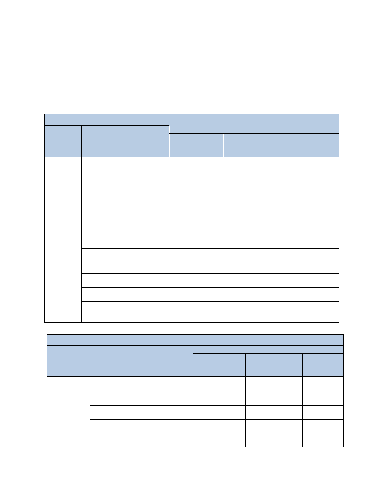
2.3 QTH LAMP COMPATIBILITY
Newport Corporation offers all the components required toassemble a complete illumination system. The
minimum components include a lamp, lamp housing, power supply, and possibly a socket adapter. The
table below explains which componentsare compatiblewith each othertocreatean illuminationsystem.
OPS-Q250 Series LampCompatibility Table
Power
Supply
Lamp or
IR Emitter
Lamp Rating,
Description
Compatible OrielLamp Housingsor Rod Mounts
Q
Housing
[Socket
Adapter]
Research
Lamp
Housings
[Socket
Adapter]
Rod
Mount
OPS-Q250
63358
QTH
45W
(
CA
L
IBRA
TED)
n/a
n/a
63966
63360
QTH
45W
(
UNCA
L
IBRA
TED)
n/a
n/a
63966
6332
QTH 50W
(SHORT FILAMENT)
60000 Housing
w
ith
60090 Interface
Kit
[60043]
66881, 66882,
66883,
66884, 67009,
67011
[60043]
n/a
6337
QTH 50W
(LONG FILAMENT)
60000 Housing
w
ith
60090 Interface
Kit
[60043]
66881, 66882,
66883,
66884, 67009,
67011
[60043]
n/a
6333
QTH 100W
60000 Housing
w
ith
60090 Interface
Kit
[60043]
66881, 66882,
66883,
66884, 67009,
67011
[60043]
n/a
6363
IR EMITTER 140W
60000 Housing
w
ith
60090 Interface
Kit
[60041]
66881, 66882,
66883,
66884, 67009,
67011
[60041]
n/a
63355
QTH
200W
(
CA
L
IBRA
TED)
n/a
n/a
63966
63368
QTH
200W
(
UNCA
L
IBRA
TED)
n/a
n/a
63966
6334NS
QTH 250W
n/a
66881, 66882,
66883,
66884, 67009,
67011
[60043]
n/a
OPS-Q1000 Series LampCompatibility Table
Power
Supply
Lamp
Lamp Rating,
Description
Compatible Oriel Lamp Housingsor Rod Mounts
Q Housing
[Socket Adapter]
Research Lamp
Housings
[Socket Adapter]
Rod
Mount
OPS-Q1000
6336
QTH 600W
n/a
66885, 66886
[6392NS]
n/a
6317
QTH 1000W
n/a
66885, 66886
[6392NS]
n/a
6315
QTH 1000W
(FEL)
n/a
66885, 66886
[6397]
n/a
63350
QTH 1000W
(CALIBRATED)
n/a
n/a
63965
63362
QTH 1000W
(UNCALIBRATED)
n/a
n/a
63965

90074225 MOPS-Q QTH Lamp Power Supplies
Page 11
3 SYSTEM SETUP
3.1 ITEMS INCLUDEDWITH SYSTEM
Oriel Instruments provides lamp interconnection cables with the lamp housing. The power supply
includes the following items:
▪Power Supply
▪Power Cord
▪User’s manual
3.2 UNPACKING
Remove all items from the shipping containers and verify each item is accounted for. The system is
carefully packaged tominimize the possibilityof damage during shipment. Inspect the shipping boxes for
external signs ofdamage or mishandling. Inspect the contentsfor damage.
If any item is missing or damaged, immediately contact Oriel Instrumentsor the Newport representative
from whom the system was purchased. It is suggested to save the packaging material and shipping
container, in casethe equipmentneeds tobe relocated ata future date.
When handling this power supply, hold it from underneaththe housing. Never use any knobs, buttons or
cables to carryor locate the power supply.
WARNING
Do not attempt tooperatethis equipmentifthereis evidence ofshipping
damage or there is suspicion that the equipment will not operate
correctly. Damagedequipmentmaypresent hazards.
3.3 CHOOSING A LOCATION
Choose an installation location where the powerrequirements can be met for the system. Be sure power
is not applied to the system until the setup hasbeen completed.
The environment should be that of a typical laboratory atmosphere, without excessive humidity and
contaminants in the air. Do not allow the ventilation holes on the power supply to be blocked. Airshould
be able tocirculate freelyaround the unit.
Once the connections have been made to the back of the power supply, the unit can be operated by
using the controls located on the front panel. Ensure that the final location allows for ease of access to all
front panel functions.

90074225 MOPS-Q QTH Lamp Power Supplies
Page 12
3.4 POWER SUPPLYCONNECTIONS
3.4.1. Front Panel Controls/Connections
Figure 2 OPS-Q Power SupplyFront Panel
Connections.
A. USB. The USB connectoron the front panel is used to install firmware and LCD GUI updates tothe
power supply. Any firmwareupdates, please visit OPS-Q power supplyproduct page.
B. Horizontal menubuttons. These four horizontal menu buttons are for using setting and monitoring
various features of the power supply:
a. Lamp OperatingMode
b. Manual/TimedShutter Control, DisplayFeatures
c. Saving/loadingparticularsetups.
C. SHUTTER. This button is for manual control of an electronic TTL input shutter. When pressed, the
shutterwill open/close.
D. Vertical menubuttons. These four vertical menu buttons are for navigatingsettings for each feature
associated with pressingthe horizontalmenu buttonsofthe power supply.
E. CLEAR. The CLEARbutton is for exiting the feature menu currently displayed on the LCD screen.
This button is also used to clearany error messages thatare displayed.
90074225 MOPS-Q QTH Lamp Power Supplies
Page 13
F. LAMP. The LAMP button is for manualcontrol ofthe lamp. When pressed, the lamp will ignite/power
down.
G. Control knob. The control knob is for setting the parametersspecifictoeach power supplyfeature.
H. POWER. This is the AC mains power switch. In the ON position as shown in Figure 2, AC powerwill
be switched into the main circuitry of the power supply. There is no output from the power supply
until the manual or external command to supply power to the lamp is received with the interlock
conditionsatisfied.
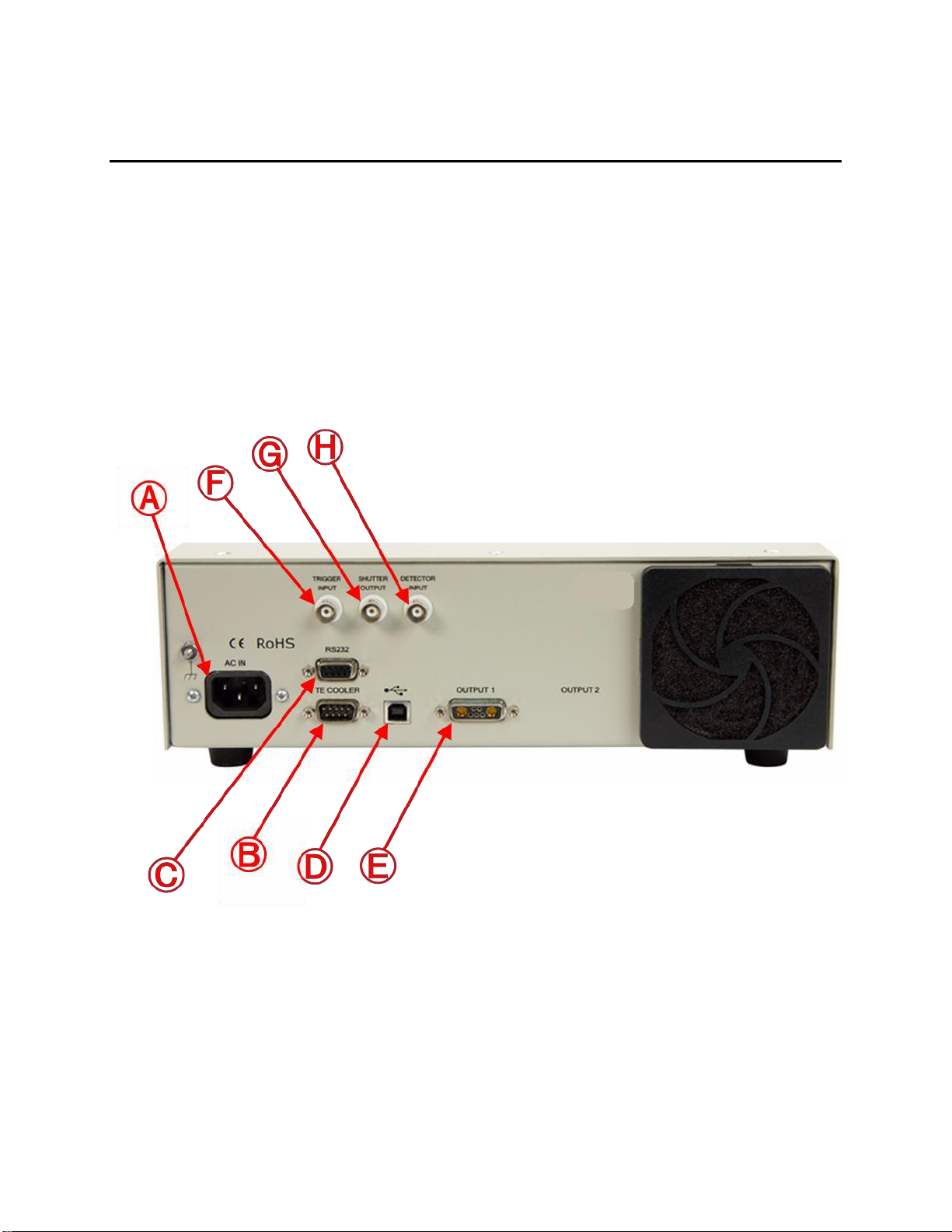
3.4.2. RearPanelControls/Connections
Figure 3 OPS-Q Power SupplyRear Panel
Connections
A. AC IN. Before powering up the system for the first time, it is suggested tohave a qualified electrician
verify the wall socket tobe used withthe power supply meetstherequirementsfor operationas noted.
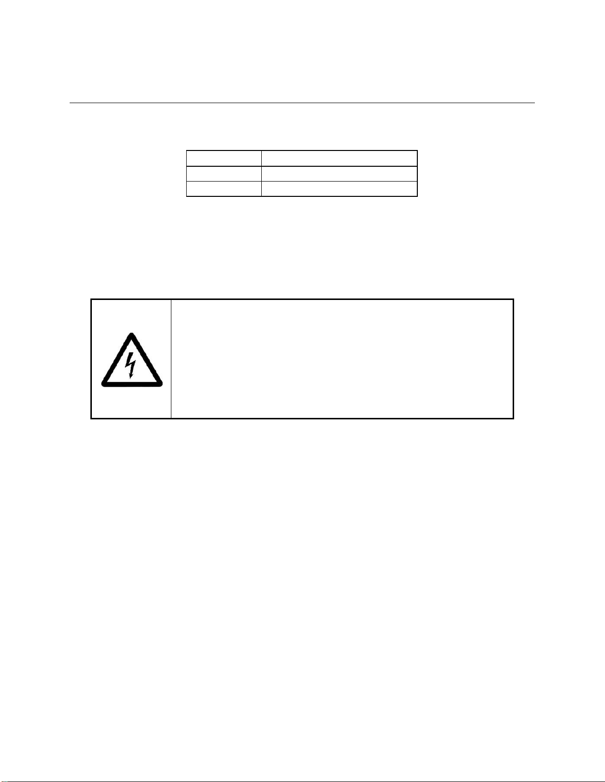
The line voltage requirementsfor the OPS power supplies are as follows:
90074225 MOPS-Q QTH Lamp Power Supplies
Page 14
Model
Input Rating
OPS-Q250
90 to 264 VAC, 47 to 63 Hz
OPS-Q1000
95 to 264 VAC, 47 to 63 Hz
A dedicated power line or line isolation may be required in certain locations, as the electronics contained
in the instrument are sensitive to static electricityand radiated electromagnetic fields. Operation of the
system near intensepulsed sources (lasers, Xenon flash lamps, etc.)maycompromiseperformance.
Before making any electricalconnections,verify the power switch is in the OFF positionfor the OPS.
Connect the powercord tothe back ofthe OPS before plugging itinto an ACelectricaloutlet.
ELECTRICAL SHOCK HAZARD
To avoid electric shock, connect the instrument to a properly earth-
grounded, 3-prong receptacle only. Failure to observe this precaution can
result in severe injury or death.
Never attempt toopen the powersupply. These models do not contain any
user serviceable parts. Failure to follow this warning can result in severe
injury or death.
The OPS product family conforms to CE standards for both safety and EMC. During normal use, this
equipment will not pose any electrical hazards to the user. Read all warnings before installing or
operatingthis system. Neveropen the OPScover and attempt to work inside.
Use the power cord provided withthe power supply. Never alter the power cord in any way. Be sure to
periodically inspect the power cord and replace it if any damage occurs. If a replacement power cord is
required, please contact Oriel Instruments do not attempt to replace the power cord with a similar cord
from a third party vendor. Use of a different line cord may not meet the electrical specifications required
touse this power supply in a safe manner.
B. TE COOLER. The LIK-LMP light intensity controller kit utilizes a TE cooled Si detector as its light
sensing head. The TE COOLERconnectoron the rear panel of the power supply is for monitoring and
controlling the temperature of the Si detector based on the 0-25 ° C temperature control range of the
OPS-Q Model Power Supply. The cable included in the LIK-LMP (also available separately as a spare
cable) is the 70062 Oriel ThermoelectricCooler to TE Cooled Detectorscable.
C. RS232. The RS232 connector located on the rear panel of the power supply allows for external
control of the power supply from a Windows based PC. The Command Set for RS232 control is in
Appendix B ofthis manual.
D. USB. The USB connector located on the rear panel of the power supply is for providing an alternative
external control methodto RS232. The CommandSet for USB control is in AppendixB of this manual.

90074225 MOPS-Q QTH Lamp Power Supplies
Page 15
E. OUTPUT 1. The interconnection cables between the lamp housing and power supply are noted in the
table below. A safety interlock feature does not allow the lamp to start if the cable or cables are not
connected. Never alter these cables and do not use if they appear to be damaged. Fully tighten all
connectionsbetweenthe lamp housingand the power supply to preventarcing.
Model
Lamp Type
Lamp Housing InterconnectionCable
OPS-Q250
QTH, IR
Oriel model 70050(Black)
OPS-Q1000
QTH
Oriel model 70050(Black)
If a replacementcable is needed,please contact OrielInstruments. Oriel Instrumentscan only guarantee
that the OPS Power Supply will meetperformancespecificationsand be operated safely iflamp housing
interconnectioncablesprovidedby Oriel Instrumentsas listed inthe table above or the table in Section 8
Interlock Cables/Connectionsto Lamp Housingsare used. The use of a lamp housing
interconnectioncable provided by a third party vendor or made on the user’s end could damage the
power supply and lamp housingand pose an electrical shockrisk to the user.
The connectorpin assignmentsare listed in the followingtable.
Pin
Signal
Description
A1
LAMP(-)
Connection to lamp negative terminal
A2
LAMP (+)
Connection to lamp positive terminal
1
GND
Ground for interlock (fan/elapsed time indicator if in housing
2
INTERLOCK(+)
Connected to +12V to satisfy interlock
3
+12 VDC
DC voltage for interlock (fan/elapsed timeindicator if in housing)
4
IGNITOR DRIVE
Momentaryground connection to fire Newport ignitor
5
INTERLOCK(-)
Connected to GND to satisfy interlock
MATING CONNECTOR:
Body: ITT# DAM-7W2P-K87(includespins 1-5)
Pins: ITT# DM 53745-1 (requires 2 per connector,A1 andA2)
Backshell:standard 15-pin D-SUB
ELECTRICAL SHOCK HAZARD
When operatingthe power supply above 60 V, a significant electrical shock
risk is present. Before operating the power supply, please inspect the
Lamp Housing Interconnection cable and confirm the cable is securely
connected to the power supply and lamp housing. Failure to observe this
precautioncan result in severe injury or death.
90074225 MOPS-Q QTH Lamp Power Supplies
Page 16
CAUTION
Do not turn on the power supply until the lamp has been installed and all
connections have been made to the power supply and lamp housing.
WARNING
When the Lamp On button is depressed, the lamp will begin emitting light.
Do not press the Lamp On button until the output flange is directed in such a
way that people, animals and equipmentwill not be harmedby the light.
If there are any questions or concerns, contact Oriel Instrumentsor the regional sales representative for
Newport.
F. TRIGGER INPUT. The BNC connector labeled TRIGGER INPUT is to remotely control the operation
of a shutterthat is connected tothe power supply. A TTL signal may be input to the
T
RIGGER INPUT
connectoror a remote switch closure maybe wired to the connector.
G. SHUTTER OUTPUT. The BNC connector labeled SHUTTER OUTPUT outputs a TTL signal to an
external electronic shutter to open/close the shutter based on the manual or external (RS232/USB)
commandsinput by the user.
H. DETECTOR INPUT. The 71582 detector head of the LIK-LMP light intensity controller kit is a TE
cooled Si detector that outputs a current signal proportional to the light output of the lamp, which is input
to the power supply via the DETECTOR INPUT BNC connection. This current signal allows the OPS-Q
Model Power Supply to raise/lowerpower/current as necessary to maintain a stable light output. This
additional level of stability is required for applications that need a highly stable light source or when the
user ops touse Intensityor Dosed Exposure operation modes.
90074225 MOPS-Q QTH Lamp Power Supplies
Page 17
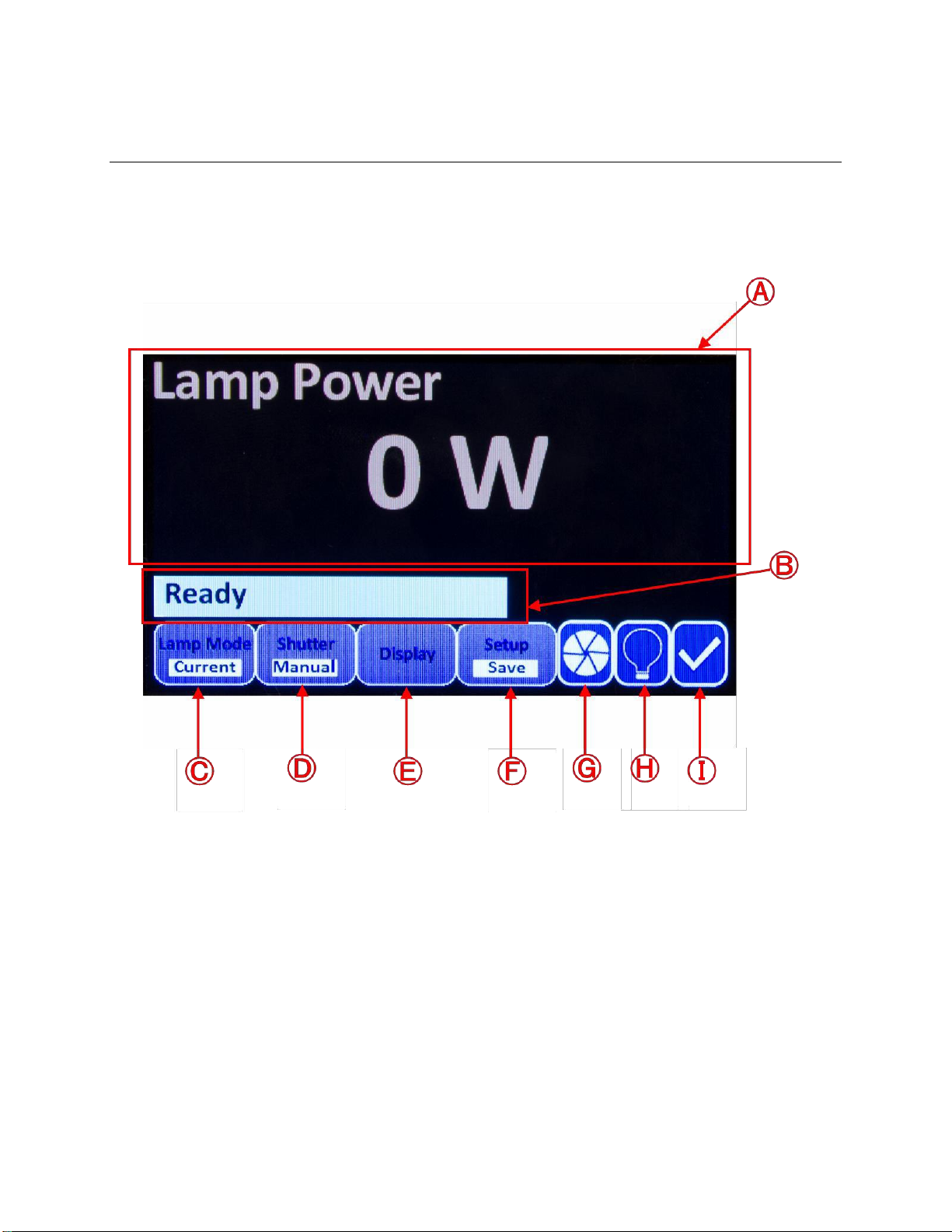
3.5 INITIAL START-UP SCREEN
Upon powering up the OPS-Q Model Power Supply. The following screen will appear on the power
supply’s LCD:
Figure 4 The LCD displayof the OPS-Q Model Power
Supply.
A. The main section ofthe LCD screen displays the desired parameteras selected by the user and will
be used for menu navigation.
B. This portion of the LCD screen displays a “Ready”status indicating the power supply and related
components(lamp, lamphousing,cable(s))are preparedfor lampignition,or displays “InterlockOpen,”
indicating a problem with the system setup. Similar error messages such as “Cooler Not Ready”
when using the LIK-LMP Light Intensity Controller kit and “Function Not Available” may also be
displayed here. The meaning of these error messages and troubleshooting techniques are explained
in the relevant portions ofthis manual.
C. Lamp Mode. The operatingmode as designatedby the user will be displayedby this indicator.
D. Shutter. The setting of the shutter, manual or timed, as designated by the user will be displayed
here.

90074225 MOPS-Q QTH Lamp Power Supplies
Page 18
E. Display. Pressing the horizontal menu button under this icon will reveal the vertical menu listing the
displayoptions available by the OPS-Q ModelPower Supply.
F. Setup. Pressing the horizontal menu button under this icon will allow the user to Save and Load
preferred settings, reset the amount of hours the OPS-Q has been recording for the current lamp in
use, and access otherfunctions of the power supply. More details on the functions accessible with
the menu button under this icon are explained throughoutthis manual.
G. ShutterIndicator. This icon displaysthe open/closestatus ofthe shutter.
H. Lamp Indicator. This icon displaysthe ignition status ofthe lamp.
I. This icon will display either a Check Mark, indicating lamp housing connections and lamp housing
door are properly secured, or an Exclamation Point, indicating the connectionsand/ordoor previously
referenced need to be re-examinedfor secure connection(s)
4 QUICK START GUIDE
4.1 SETTINGLAMP PARAMETERS
1. Press the horizontal menu button under the Lamp Mode icon. If Power Mode is desired, press the
horizontal menu button under the Lamp Mode indicatoruntil Power appears under Lamp Mode. If
Current Mode is desired, pressthis menu buttonuntil Current appears under lamp mode.
2. Upon choosing a lamp mode the operating power/current (Pset/Iset) and maximum operating
power/current (Pmax/Imax) will appear on the vertical menu. Press thevertical menu button next to
Pset/Iset and use the knob toset this parameterwhen a red bullet appears next to the current value.
Then, set Pmax/Imax. This is typically setto10% above the rated power/current for the lamp being
used.
Be aware that the Imax setting will determine the maximum current the power supply will supply to
the lamp, even if the lamp is being operated in Power mode. If the lamp is being operated in Power
mode and not reaching the Pset as directed by the user, turn off the lamp. Then, increase Imax while
staying within the lamp’s maximum current specification. Revert back toPower operation mode and
ignitethe lamp.
Please note that Power, Current,and Intensity Modesshare the same Imax setting. Changing
the Imax setting in one mode of operationwill change the Imax setting for the other modesof
operation. Before igniting the lamp, the maximum specifications should be confirmed and
presetby the user to avoiddamageto the lamp.
4.2 TURNING THE LAMP ON/OFF
When the lamp parameters have been set, press the LAMP button on the front panel. The OPS-Q
Series PowerSupplies have a Soft Start feature. These power supplies gradually apply poweror
current on lamp start-up and gradually reduce power or current on lamp shut-down. This prevents
catastrophicdamage tothe filament from in-rush current on lamp start, and minimizesstress to the
lamp. The reduction in thermal shock tocalibrated lamps ensures longer validity of the calibration.
As a result, a user may notice the QTH lamp/IRemitterdoes not instantly ignite or power off when
directed by the user/powersupply.

90074225 MOPS-Q QTH Lamp Power Supplies
Page 19
4.3 LIGHT INTENSITYCONTROL
1. The flux set point must be set first. There are two ways toset the flux set point:
A. AutoSet method:
i. Use “Current” or “Power” mode to turn ignitethe lamp first
ii. Press the horizontal menu button under “Display”and select “Lamp Intensity”
using the externalknob.
iii. Press the right mosthorizontalmenu key under Setup until the vertical menu with
CoolTemp, Idle, and Autosetappears.
iv. Press the “AutoSet” button, the systemwill automatically adjustthe gain of the
flux amplifierand set the flux set point to be 90%ofcurrent flux reading
v. Turn off lamp
B. Manual method:
i. Use “Current” or “Power” mode to turn ignitethe lamp first.
ii. Press the horizontal menu button under “Display”and select “Lamp
Intensity”using the external knob.
iii. Record this value. This value is to be used as the “Flux Set” set point.
iii. If the recorded value shows value of 2.5uA, 25uA or 250uA or 2500uA,
this indicates that the flux reading has overflowed with existing gain of
flux amplifier. If this occurs, the Autoset Method described above should
be used.
iv. Turn off the lamp.
v. Press the horizontal menu key under “Lamp Mode”and continue this
button until Intensityappears.
vi. When Intensity appears, press the vertical menu button next toFlux Set.
Use the knob to change this value to10% greaterthan the Flux Set point
just recorded.
Users who used the Manual Method describedabove to establish a Flux Set point can skip Steps
2 and 3 and proceed withpressingthe LAMP button to operate the lamp.
2. To change the lamp control mode, use the horizontal menu key under “Lamp Mode”and
press this button until Intensity appears.
3. Once Intensity modeis selected, press thevertical menukey next to Flux Set and use the
knob to adjust this value. Press the LAMP button toignitethe LAMP.

90074225 MOPS-Q QTH Lamp Power Supplies
Page 20
4. When in “Intensity”mode, if the signal output and/or TE cooler cables connecting the power
supply to the 71582 light intensity control kit detectorare not connected properly, “Cooler
Not Ready”may appear on the message bar of the LCD screen. If this appears, inspectthe
cables to confirm secure connections.
5 OPERATING MODES
5.1 POWERMODE
In power mode, the lamp is operated at a constant powersetting. As the voltage cannot be changed, the
current is raised or lowered tomaintain the powerat the same level. As the lamp ages, the radiant output
decreases. As an IRemitterages, its resistancemaydouble. However, the lamp life is prolonged.
5.2 CURRENT MODE
In current mode, the lamp is operated at a constant current setting. As the voltage cannot be changed,
the power is raised or lowered tomaintain the current at the same level. As the lamp ages, the power is
increased. This results in greater optical output which to some extent may help compensate for a
darkeninglamp envelope. However, the lamp life is reduced due tothe increase in power.
5.3 INTENSITYMODE
Light intensity mode allows the user to increase or decrease the output intensity ofthe lamp from a Flux
Set point. In order operate the lamp in Intensity Mode, the LIK-LMP Light Intensity Controller Kit (sold
separately) from Oriel Instruments is required. The LIK-LMP light intensity kit includes a TE cooled
detector, and all the necessary adapters and cables for mechanical and electrical compatibilitywith the
lamp housing (both 60000 Q Series and 45-1000 W Oriel Research Lamp Housings adapters included)
and OPS model power supply. While operating in Intensity Mode, varying the Flux Set parameterallows
the user to increase/decrease the output power intensity of the lamp during operation. If a calibrated
photodiode or other current output detector was used to determine the desired output intensity of the
lamp while the Flux Set was being adjusted, the flux (labeled as Output Intensity) displayed on the LCD
screen of the power supply can be adjusted to match the current output of the calibrated detectorby the
use of the Flux Cal Factor. Withthe use of the LIK-LMP, Intensity Mode ensures stable operation ofthe
establishedflux set pointof the lamp over long operationperiods.
5.3.1. Dosed Mode
Dosed mode is a special operating feature of Intensity Mode. When the lamp is in intensity control
mode and a TTL shutter is used, a user can set the Dose for the lamp to output. A Dose consists of a
flux and a time interval. When a user sets a flux set point in intensity mode and switches to dose
mode, a Dose should be specified by the user. The user should also specify the time interval for the
shutter to remain closed in between individual exposures of this Dose, and the amount of cycles
he/she would like this Dosed exposure to repeat for. Time is not directly set by the user, the time
interval the shutter remains open allowing the lamp to directly output light is determined by the power
supply based on the flux set point and the Dose as desired by the user. While operating in Dosed
mode a user can Stop a cycle of exposures, pause the current cycle while the shutteris closed, or
reset the Total Dose the lamp has output thus far as recorded bythe power supply.
This manual suits for next models
1
Table of contents
Other Newport Power Supply manuals


Popular Power Supply manuals by other brands

Liebert
Liebert Ship-Ahead Input/Output Cabinet NXL installation manual

Monacor
Monacor PSS-3800SV operating instructions

Elsner
Elsner KNX PS640+ Installation and adjustment

mini-box
mini-box M2-ATX-HV installation guide

Vahle
Vahle VKS10 Mounting instructions - Maintenance

Antec
Antec BASIQ BP-500U user manual


