6 - NET LAMP- Ver. 03 NET LAMP- Ver. 03- 7
D811475_03
FRANÇAIS
MONTAGEANLEITUNG DEUTSCH
MANUEL D’INSTALLATION
1) ALLGEMEINES
NET LAMP ist die Blinkleuchte von FAST NET. NET LAMP muß an eine Zentralsteuerung angeschlossen werden, die
eine Verbindung des Typs FAST NET unterstützt.
Die Blinkleuchte darf ausschließlich zusammen mit Steuerungen des Herstellers benutzt werden.
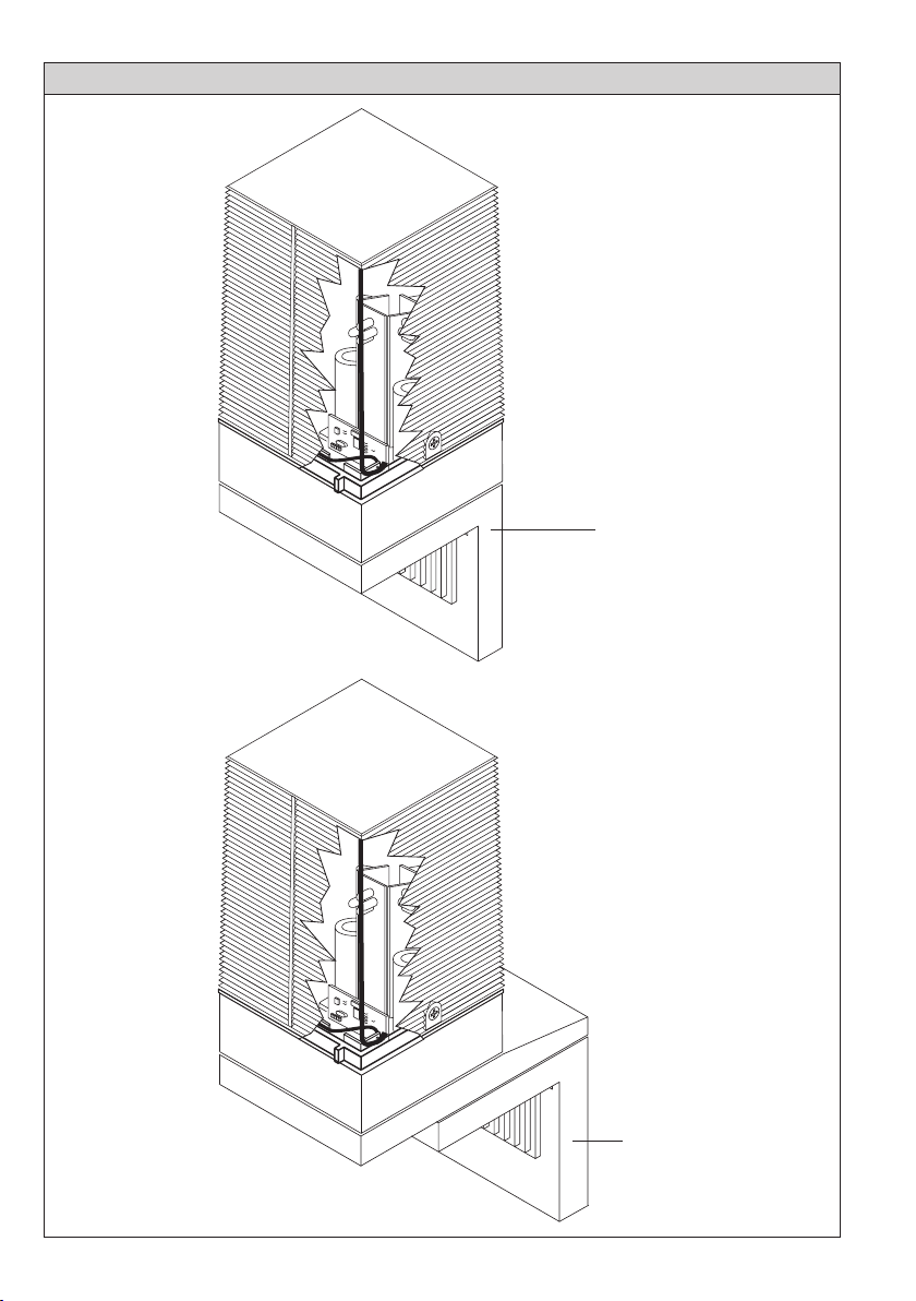
2) MONTAGE
a) Direkte Vertikalmontage (Abb. 1).
b) Montage an der Wand (Abb. 2) mit Wandmontage-Set Mod. SLM2 (Zubehörteil)
In vertikaler Position beträgt der Schutzgrad der Warnblinkleuchte IP44.
VORSICHT! Metallgegenstände in Antennennähe können den Funkempfang stören.
c) Das gelbe Kabel (A) und das schwarze Kabel (B) müssen dem angegebenen Streckenverlauf folgen (Abb. 3).
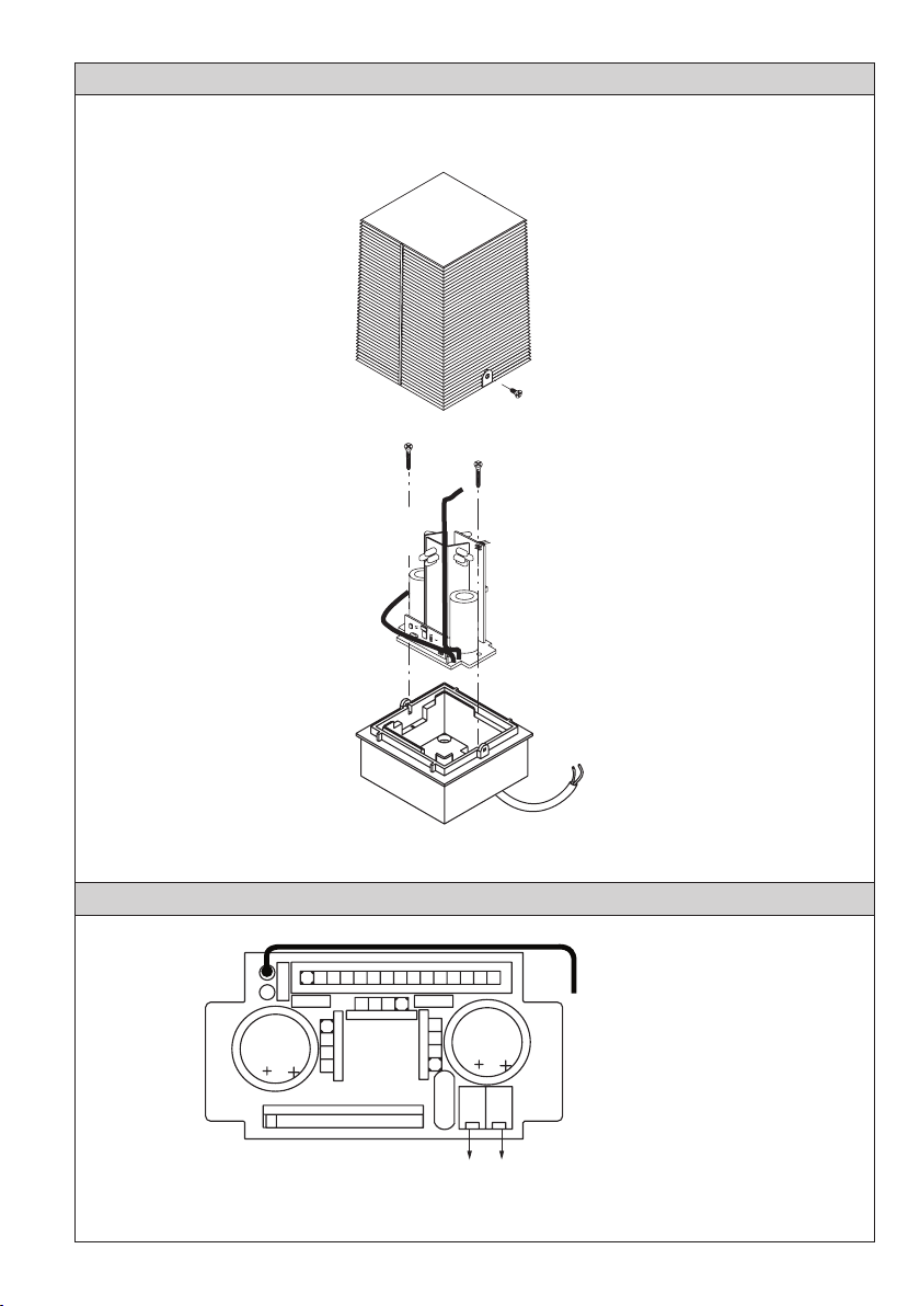
3) ZUSAMMENBAU
Bauen Sie die einzelnen Teile entsprechend Abb. 1 zusammen.
3.1) KLEMMLEISTENANSCHLÜSSE (Fig. 1A)
JP1 Versorgungsspannung (LINE)
JP2 Eingang Antenne (ANT)
ACHTUNG! Für den Anschluß nur eine Telefondoppelader benutzen; diese darf nicht polarisiert sein.
Achtung! Die Installation muß von Fachleuten vorgenommen werden. Vor jedem Eingriff an der Anlage ist die
Stromversorgung zu unterbrechen.
NET LAMP ist an eine Zentrale anzuschließen, welche die Verbindung des Typs FAST NET unterstützt.
Sowohl die Speisung, als auch die Übertragung läuft bei den Einrichtungen FAST NET ausschließlich über Telefon-
doppeladern ab. Die Doppelader ist nicht polarisiert: NET LAMP ist parallel geschaltet an die Klemmen FAST NET der
Zentrale anzuschließen und so zu adressieren, wie im Abschnitt “Adressierung” ausgeführt. Wenn die gesamte Anlage
verkabelt ist, müssen die Vorrichtungen FAST NET angelernt werden, wie es in der Betriebsanleitung der benutzten
Zentrale beschrieben ist.
4) ADRESSIERUNG (Abb. 4).
NET LAMP besitzt einen 2-Wege-Dipschalter zur Adressierung der Vorrichtung. In einem Netz FAST NET lassen sich
maximal 4 Blinkleuchten NET LAMP anschließen, davon 2 mit Funkkarte, wenn die Gesamtzahl der 16 anschließbaren
Vorrichtungen nicht überschritten wird. Die Blinkleuchte NET LAMP ohne Funkkarte nimmt einen Platz ein, während
sie mit Funkkarte zwei Plätze einnimmt.
Innerhalb eines Netzes FAST NET kann jede Adresse nur von einer einzelnen
Vorrichtung verwendet werden, es ist also nicht möglich, mehr als eine NET LAMP mit derselben Adresse anzuschließen.
Zur Prüfung der von den Dipschaltern vorgegebenen Adresse siehe die Tabelle in Abb. 4.
5) FUNKKARTE
Die Funkkarte läßt sich in NET LAMP integrieren, indem man das Kleinmodul in den Steckplatz JP3 einfügt, wie in der
Zeichnung von Abb. 3 dargestellt.
6) WARTUNG
GEFAHR! Vor jeder Art von Wartung oder Instandsetzung muß die Stromversorgung unterbrochen werden.
Reinigen Sie regelmäßig die Haube der Blinkleuchte.
1) GENERALITES
NET LAMP est le feu clignotant de FAST NET. NET LAMP doit être connecté à une centrale qui supporte la connexion
FAST NET.
Le feu clignotant ne doit être utilisé qu’avec les unités de commande duconstructeur.
2) MONTAGE
a) Montage vertical direct (fig. 1).
b) Montage vertical mural (fig. 2) avec support mod. SLM2 (accessoire)
En position verticale, le degré de protection est IP44.
ATTENTION! La présence de masses métalliques adossées à l’antenne peut déranger la réception radio.
c) Le câble jaune (A) et le câble noir (B) doivent suivre le parcours indiqué (Fig. 3).
3) ASSEMBLAGE
Assembler les parties comme indiqué à la fig. 1.
3.1) CONNEXIONS DU BORNIER (Fig. 1A)
JP1 Alimentation (LINE)
JP2 Entrée antenne (ANT)
ATTENTION! Pour la connexion utiliser uniquement un fil duplex de type téléphonique, le fil duplex n’est pas polarisé.
Attention! L’installation doit être effectuée par du personnel qualifié. Avant d’effectuer n’importe quel type d’intervention
sur l’installation, couper l’alimentation. NET LAMP doit être connecté à une centrale qui supporte la connexion FAST
NET. Les dispositifs FAST NET utilisent seulement un fil duplex de type téléphonique soit pour l’alimentation que pour la
communication. Le fil duplex de type téléphonique n’est pas polarisé. Connecter NET LAMP en parallèle sur les bornes
FAST NET de la centrale ; adresser NET LAMP comme indiqué dans le paragraphe d’adressage. Apres avoir complété
le câblage de toute l’installation, effectuer la procédure d’apprentissage des dispositifs FAST NET comme indiqué dans
les instructions de la centrale utilisée.
4) ADRESSAGE (Fig. 4)
Un interrupteur Dipswitch à 2 voies pour adresser le dispositif est présent sur NET LAMP. Dans un réseau FAST NET
il est possible de connecter jusqu’à un maximum de 4 feux clignotants NET LAMP dont jusqu’à un maximum de 2 avec
carte radio sans excéder le numéro maximum total de 16 dispositifs connectés. Le feu clignotant NET LAMP sans carte
radio occupe une place, tandis qu’avec la carte radio il occupe 2 places. Dans un réseau FAST NET chaque adresse
peut être utilisée par un seul dispositif, c’est à dire qu’il n’est pas possible de connecter plus qu’un NET LAMP avec la
même adresse. Pour vérifier l’adresse programmée par les DSW, s’adresser aux tableaux de la Fig. 4.
5) CARTE RADIO
Il est possible d’intégrer sur NET LAMP la carte radio en insérant le module dans le connecteur JP3 comme indiqué sur
le dessin de la figure 3.
6) ENTRETIEN
DANGER! Couper l’alimentation de la motorisation en cas d’interventions d’entretien ou de réparation.
Nettoyer périodiquement la calotte du clignotant.