BGU WK 600 B CLASSIC User manual

Südharzer Maschinenbau GmbH
Helmestraße 94 ∙ 99734 Nordhausen/Harz
Zentrale: 03631/6297-0 6297-111
Internet: www.bgu-maschinen.de
e-mail: [email protected]
LOG SAW
WK 600 B CLASSIC
Carefully read these instructions
before starting and using your saw!
OPERATION MANUAL
Set-up & instal-
lation
Use
Maintenance
Accessories
Made in Ger-
many

2
TABLE OF CONTENTS
1. GENERAL INFORMATION 3
1.1 About the manual 3
1.2 Delivery and transport claims 3
2. PRODUCT OVERVIEW 5
2.1 Log-saw with gasoline engine 5
3. DECAL LISTINGS 6
4. SAFETY RULES 8
4.1 Safety rules about saw blade 9
4.2 Mandatory application field 9
5. OPERATION 10
6. REPAIRS AND MAINTENANCE 11
6.1 First maintenance after initial start-up 11
6.2 Ordinary maintenance 12
6.3 Cleaning after use 12
6.4 Replacing the saw blade 12
6.5 Tensioning and replacing the V-belt 13
6.6 Consumables 13
7. HANDLING AND Transport 14
8. DISPOSAL 14
9. Technical Data 15
9.1 Noise emissions 15
10. TROUBLE-SHOOTING CHART 16
11. OTHER AREAS OF POSSIBLE HAZARD 16
11.1 Mechanical dangers 16
11.2 Environmental dangers 16
12. WARRANTY 17
13. SPARE PARTS for WK 600 B classic 18
14. CE – STATEMENT OF COMPLIANCE 23

3
Dear customer,thank you very much for your trust and preference in
choosing our equipment and joining the number of our best custo-
mers in the world. We are confident that our equipment will be up to
all your expectations and assure you a long lasting quality and perfor-
mance.
1.1 About the manual
Please take time to read this manual and learn to how operate and
maintain the saw safely.
For your easier reading this manual is laid out in several sections pro-
gressively numbered 1 through 14 and listed on the “content” page.
The information, pictures and technical data in this document reflect
current or planned product features, functions, and characteristics as
of the publication date. Because of on-going product improvements
and feature additions, information in this document is subject to
change without notice.
If you are experiencing a problem or functional trouble on your machi-
ne, please read the “trouble-shooting” section to identify possible cau-
ses and remedies. If the problem or functional trouble is not listed in
the troubleshooting chart contained in this manual, ask your Authori-
zed Service Centre for service. When you have checked all the possib-
le causes listed and you are still experiencing the problem, ask your
Authorized Service Centre for help.
When you order parts maintenance or repair services, your Authorized
Service Centre, your dealer or eventually the manufacturer need your
machine serial number and engine serial number. These are the num-
bers that you have recorded on the product identification label of the
manufacturer on the machine.
1.2 Delivery and transport claims
Upon delivery of the machine please check for visual machine dama-
ges such as damaged packing or scratched buckled parts. If so, make
a remark on all copies of the delivery bill before signing for accep-
tance.
Also have the truck driver sign al copies of the delivery bill.
Should your shipper or the truck driver refuse to accept your claim,
fully reject delivery and make sure to inform us (the manufacturer)
immediately. No claims shall be taken into account by the shipper or
by the insurance company, if a reservation note is not made on the
delivery bill.
1. GENERAL INFORMATION

4
All transport damages including hidden ones must be notified within
latest 2 days from delivery. Therefore delivery must be collected and
inspected within this term. Later claims shall be disregarded.
In case of assumed but not visually clear transport damages make su-
re to mark the following sentence on the delivery bill: „Reserved de-
livery due to assumed transportation damages.“
Insurance and shipping companies act with extreme caution in case of
transport damages and sometimes refuse to accept responsibility.
Please make sure to provide clear and exhaustive evidence (photos)
of the claimed damages.
Thank you in advance for your help and understanding in this matter.
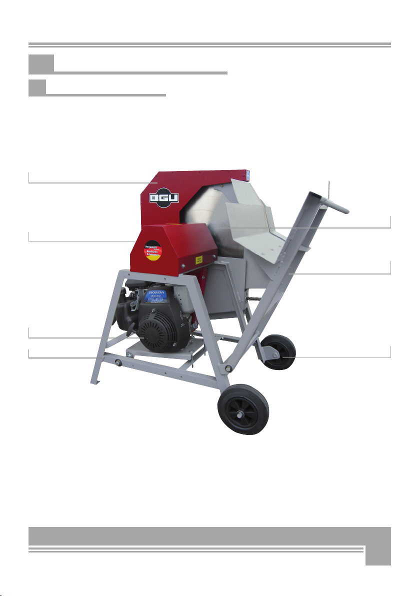
5
Rear grip-handle
2.1 Log-saw with gasoline engine
2. PRODUCT OVERVIEW
Upper hood
Gasoline engine
Stand Wheels
Log carriage
Saw blade

6
1. Warning label „Do not operate the machine in-
doors!“
Never run the machine inside a closed area.
Exhaust fumes are toxic!
2. Aufkleber
Safety pictogram
„Wear ear plugs and goggles!“
Loud noise can cause impairment or loss of hearing, wear a suitable
protective device such as ear plugs and safety goggles.
3. Personal protection sign
Mind these instructions for safe operation!
4. Machine safety label
„Before operating the machine read this manual
and mind all safety instructions“
To avoid personal injury or death, carefully read and understand all
instructions pertaining to the saw including the engine manufacturer’s
operating and maintenace instruction manual.
5. Safety-alert symbol
Read and recognize safety information. Be alert to the potential
for personal injury when you see this safety-alert symbol.
6. Personal protection sign “Wear suitable protec-
tive boots!”
7. Personal protecion sign “Wear suitable protect
ve gloves!”
This label shows that you must wear safety gloves when working with-
the saw.
3. DECAL LISTINGS
7
8. Machine safety label
„Before setting-up, servicing, maintaining and clea -
ning the machine, disengage power and stop the en-
gine. Lock the tool and secure it against acciden-tal
start.“
This safety label reminds users of a pinched hands danger.
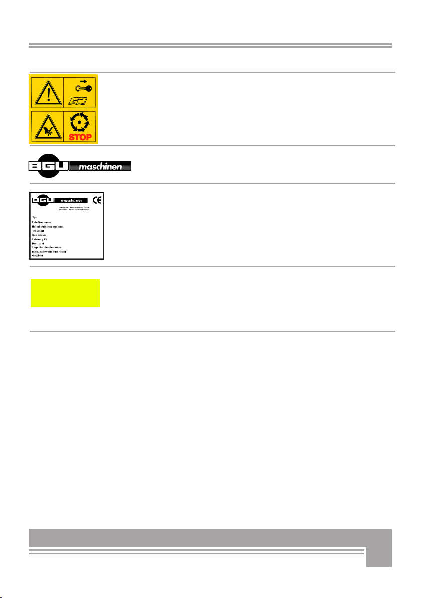
9. “BGU-maschinen” Manufacturer’s logo
10. Identification label „Product identification“
This label shows the company details of the manufacturer and the
main machine technical data.
11. Machine safety label Keep your hands off all machine
parts identified by this
label! Burning danger.
BEWARE!
hot parts

8
Strictly perform installation, set-up, maintenance, cleaning
and transportation with the motor switched off and the blade
firmly secured against accidental operation.
Immediately disconnect power off the machine in case of any
eventual fault or trouble.
Before operating the saw for the first time read and familiarize
with the instructions of the engine manufacturer!
The user shall strictly comply with these operation, set-up, mainte-
nance, repair and trouble-shooting instructions in order to assure safe
operation and no damages to the equipment. Moreover we recommend
to let the machine be run and maintained only and strictly by trained
and skilled staff who must be familiar with the applicable occupational
safety and health administration rules as well as applicable transportati-
on rules. Incorrect use of the saw can cause serious injury or death.
No person under school leaving age should operate a circular saw.
Those who have reached school leaving age but are below the age of
18 may operate a circular saw, if supervised by a competent person of
18 years or over. The machine shall be installed and kept in a suitable
location selected by the customer for safest operation.
The working area around the machine must be kept as clear as pos-
sible from surrounding obstacles and slippery foundation floors should
be duly treated (do not use saw dust or wood ash for this purpose).
Make sure that the equipment stands on a safe stable foundation.
Do not allow within the hazardous zone any unauthorized third or persons
who are not familiar with the dangers related to use and operation of the ma-
chine. Allow no bystanders, especially children and pets in the working area.
● Due and proper illumination of the working site must be provided at all times.
● The saw blade must be duly sharpened for maximum performance
and no recoil danger. Flash and chips must be removed off the
crown wheel.
● Damaged or buckled blades (very likely to break during operation)
should not be used.
● Always wear suitable hearing (ear plugs or muffs) and eye
protection(goggles or safety glasses) while operating the machine.
● Set up the machine on a firm surface which is free from stumps,
boulders and other obstructions and ensure that a wide but confined
area is available around the machine.
● Operators must wear steel toe safety shoes and snug-fitting tear-re-
sistant work cloths.
● No additional customised protections or tools should be provided on
board of the machine, other than the ones designed and supplied by
the manufacturer.
4. SAFETY RULES

9
● Do not apply pressure (for instance by means of the wood stock)
against the blade to make it come to a quicker stop.
●
The machine is not designed for indoor use (dust release).
● NEVER leave the machine unattended with the running motor.
● Before leaving the operator‘s station for any reason, stop the engi-
ne, disconnect power and secure the machine against accidental
operation.
4.1 Safety rules about saw blade
The unit is strictly designed for use with a 600mm (outer diameter)
blade. The blade (Cr) is capable to withstand a maximum number of
revolutions of 3000 rev. per minute.
Strictly use blades as per EN Standard 847-1.
Do not ever use worn out blades in need of sharpening.
Make sure that the blade shows good conditions, no damages, no
cracks, no buckling and no missing/broken teeth/bits.
Hard metal blades require special care and handling. Make sure that
the blade bits do not ever hit against hard surfaces (for example conc-
rete floors), which might cause invisible bits damage.
Hard metal blades must be suitable to operate at 3250 revolutions per
minute.
4.2 Mandatory application field
These log-cutting saws are strictly designed for preparation of fire-
wood. Sawing to be strictly performed with wood stock on the log car-
riage. All other applications are forbidden and considered as “misuse”.
The manufacturer is not liable for any damage or injury resulting from
misuse!
The machine is capable to handle wood stocks in diameter of 8-19.5
cm. Shrubs and tiny branches bundles must be loaded on the trough
and securely hold on both sides of the blade.
The machine is strictly conceived for ONE-MAN OPERATION
ONLY.
Check the tension of the V-belt before first use!
Misuse will completely void your warranty. The manufacturer
accepts no liability for personal injuries and damages to other
equipment caused by misusing the machine.

10
5. OPERATION
This log-cutting saw model WK 600 B Classic is ideally recommended
for stationary use in your yard.
A rugged all-steel construction assures longest machine life at any
operative condition.
This machine is equipped with inbuilt gasoline engine for independent
power provision. Please read the instructions of the engine ma-
nufacturer before use.
When you switch the machine on make sure to check that the blade is
mounted to rotate in the proper direction before cutting any materi-
al. The tool must rotate against the operator that is upward toward the
operator. Load the log in the carriage and smoothly push to the blade.
Make sure to avoid inhaling gasoline vapors during use.
If you working with twisted or crooked logs make sure to load the
log on the carriage, so that the bolged side of the log is turned to the
blade in order to avoid the log from tipping over or jamming during
cutting and consequent possible even major damages to the blade.
Now fasten the grip on the log carriage and push to smoothly tilt it
over towards and through the blade.
NOTE: avoid excessive pressure on the carriage through the
blade with cutting. Excessive hold-down pressure may slow the
blade down and cause dangerous jamming!
When pushing the log through the blade doing so avoid all jerky, bum-
py movements that could lead to risky and dangerous situations. Tim-
ber in maximum diameter of 200mm and length of 1.1 m must lay on
the carriage by the entire length with no projecting end.
After the first log is cut off the timber, let the carraige swing down to
start-position (wide opened) before advancing the remaining timber to
the blade and starting a new sawing cycle.
If you try to feed the stock forward and cut before the carriage rea-
ches back to start position, you may run the risk of hitting the stock
against the blade guard consequently causing severe personal injuries
and machine damages for which the manufacturer carries no liability.
If the maximum 16 mm spacing between clearance inserts (wood
strips) is reduced because of excessive wear, provide for immediate
replacement of the wooden inserts! (see Figure 1)
Fig. 1
wood strips
Saw blade
11
6. REPAIRS AND MAINTENANCE
Make sure that the machine is fully disconnected and all mo-
ving parts are secured before performing any maintenance/re-
pair work on the machine. In the event of any malfunctioning,
switch the machine off before trouble-shooting.
6.1 First maintenance after initial start-up
Check and tighten all fixation elements after 1 operation hour, in or-
der to avoid damages to the motor.
Make sure to check the torque of all fixation hardware used for the
driving pulley of the motor. Adjust torque, as necessary.
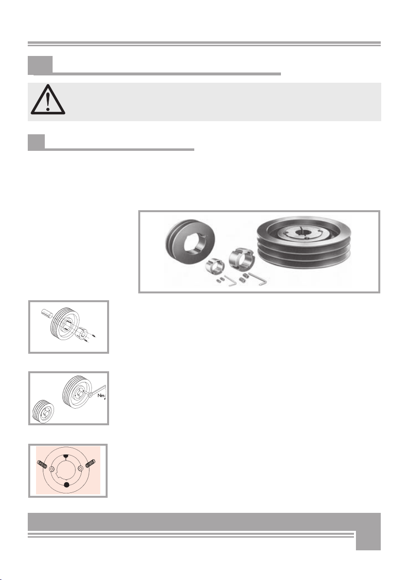
Procedure:
• Unscrew and remove the cover 2 (pos. 8 of the spare part list) over
the pulley by removing the 4 hex screws M6x16 and relative was-
hers (pos. 31, 23 see spare part list)
• Remove screw M8x25 (Pos. 41) with its spring lock (Pos. 40, of the
spare part list) and washer (Pos. 38, of the spare part list)
• Check the torque of both threaded pins and adjust them, if necessa-
ry, using a wrench 3 with 5.7 Nm torque (fig. 5)
Fig. 2
optibelt
Die Keilrillenscheiben sind vor der Neumontage auf Beschädigungen und korrekte
Ausführung zu überprüfen.
Taper-Buchsen, Schrauben-Anzugsmomente
Abmessung Schlüssel- Schrauben- Anzugs-
TB 1008, 1108 3 2 5,7
TB 1210, 1215, 1310, 1610, 1615 5 2 20,0
TB 2012
TB 2517
TB 3020, 3030 8 2 92,0
TB 3525, 3535 10 3 115,0
TB 4040
TB 4545
TB 5050
Fig. 3
Fig. 4
Fig. 5
3. Welle säubern und entfetten. Scheibe mit Taper-Buchse bis zur
5. Mittels Inbusschlüssel nach DIN 911 Stiftschrauben bzw.
Zylinderschrauben gleichmäßig mit den in der Tabelle ange-

12
Fig. 6
saw blade
Log carriage
6.2 Ordinary maintenance
The following tasks belong to ordinary maintenance works:
● Clean the machine from eventual residual wood, chips or dirt.
● Lubricate all moving parts.
● Grease all pivoting parts of the log carriage
6.3 Cleaning after use
Remove wood chips and saw dust produced and left on the machine
during work.
Clean the log carriage assembly removing all wood rests.
6.4 Replacing the saw blade
Safety note ! Wear safety gloves - pinched hands danger!
Before replacing the blade make sure to disconnect the machine
from power (unplug the electric motor or turn the tractor off).
Following instructions apply for safe and proper blade replacement:
● Disconnect power off the machine (unplug power cord or stop the
motor of the tractor) and wait for the blade to come to a complete stop.
● Tipp the upper blade hood over by releasing the 4 screws
● Release and undo the fixation bolt on the blade clamping flange
using a spanner to secure the blade flange on the motor side as you
undo the nut (spanner SW 41).
● Remove the clamping flange.
● Pull the old blade off the shaft (make sure to wear tear-resistant
gloves. DANGER!)
● Fit the new blade on the shaft. Note direction of rotation. All tools must
always work against the feed direction that is revolutions must occur
towards the operator’s station. (see Figure 6)
● Mount the locking flange back on the blade shaft minding the right
position of the feather-key in the flange.
● Tighten fixation bolt on the flange. BEWARE: when assembling the
new blade make sure to follow the dismounting procedure: saw
blade, external saw blade clamping flange, washer, fixation screw.
● Refit the blade hood in the original position duly set and clamped.
Saw blades, where tips do not any longer show through the
slot in the log carriage with the saw in its start/posions, will
have reached the end of their regrind life and shall be taken
out of service.
13
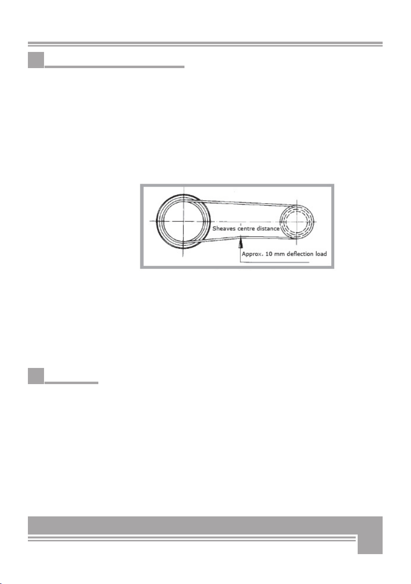
6.5 Tensioning and replacing the V-belt
If you are operating a WK 600 B model, proper maintenance requires
re-tensioning of the belt after a certain number of operation
hours. To perform stretching of the V-belt, you need adjusting the
special regulation screw located underneath the gearbox cover.
Release the engine mount fixation and adjust the V-belt so that you
can still provoke an approx. 10 mm of deflection by applying one fin-
ger tip pressure (see figure 7 - Stretching of the V-belt).
Fit the gearbox cover and the engine mount back into place before
operating the machine again.
Running the saw with a loose V-belt will cause increased wear and
shorten you belt life.
To replace the belt, release the clamp-screws and remove the
safety guard from the V-belt drive area. Remove the old belts from
the sheaves and fit the new ones on.
Make sure to refit the V-belt casing back in place before operating the
machine again.
BEWARE: failure to provide due re-tensioning will result into a less ef-
ficient V-belt drive that slips and may be wear out faster
6.6 Consumables
Consumable parts that are subject to normal wear are not covered by
the manufacturer‘s warranty. These are:
Saw blade (Code 95004 for HM versions)
Wood strips (Code 54383)
V-belt (Code 56187)
Figure 7
Stretching of the V-belt

14
These log & timber cutting saws are light equipment that can be
easily moved on short-distance by means of two caster wheels and
an ergonomic, comfortable grip handle located on the chassis on the
opposite side as the log carriage. In order to avoid infringement of the
clearance area around the machine, the grip handle can be swivelled
up and down on the model WK 600B.
Simply fasten the grip and lift the saw for safe and rapid hauling of
the machine.
For safety reasons the grip handle should remain retracted (or lifted
up) during work to avoid risk of tripping or entanglement.
7. HANDLING AND TRANSPORT
8. DISPOSAL
When the machine is fully obsolete and cannot be of any longer use,
it should be duly dismounted ahead of discarding. Certain components
need deactivation and dismantling in order to assure that no further
use is made by other parties and that no worn out parts are recycled
for other applications.
During dismantle be alert for possible recyclable materials and compo-
nents that belong to differentiated waste collection procedures applica-
ble in your country.
The manufacturer is not liable and undertakes no responsibility for per-
sonal injuries or damages that may result from the recycling of worn
out machine parts and eventual re-use in other applications different
than originally stated in this manual.
Dismantling procedure:
Take good note please: each and every dismantling task must be per-
formed by authorized service centres or trained skilled staff only!
● Lock and secure all moving parts of the machine and pull the ma-
chine down into single components
● Deliver each single component only to authorized waste manage-
ment facilities
● Remove rubber and plastic parts from the machine that must be-
separately disposed
Deactivated, clamped moving/driving parts and components are of no
further risk and danger.
15
9.1 Noise emissions
The noise level was measured in compliance with the general rules for
establishment of noise and acoustic pollution of garden and agricultu-
ral equipment on work sites as well as with other national standards
for noise measurement. The applicable measuring parameters were:
Measurement on the machine front edge at 1600 mm height and
400mm away from the blade on the right hand side, while processing
beech wood in the size of 80+/-5% of the admissible timber diameter
as per this instruction. Detected noise levels:
Without load 92 db(A)
With max load 110 db(A)
Hearing protection is mandatory!!
The above mentioned values are emission measurements and may not
be therefore assumed as for a safe work environment. Although there is
a relationship between noise emission and immission levels, this is not a
sufficient basis to determine the extent of on-site required protection.
There are a lot of other factors that can influence site work and risk of
injuries and namely: the actual site/buildings configuration,
the concomitant presence of other noise sources (for instance other ma-
chines performing other works in the neighbourhood) etc... The factors
applied for determining safety of a workplace may also very
from one country to the other. We are reporting here the noise values
detected in the facility of the manufacturer on order to allow the user
performing a better evaluation of the possible risk/disturbance.
Technical data Unit/Mea-
sure
WK 600 B Classic
Max. timber diameter mm 195 (7.6 in)
Saw blade diameter mm 600/30
Power of gasoline engine PS 5
Engine speed RPM 3600
Saw blade speed RPM 1780
Length mm 900 (35.4 in)
Width mm 680 (26.7 in)
Height mm 1030 (40.5 in)
Weight kg 95 (209 lbs)
9. TECHNICAL DATA

16
11.1 Mechanical dangers
Possible dangers related to machine moving parts (saw blade) are
minimized by means of suitable safeties and protections that cannot
be dismounted unless special tools and equipment is used. Do not
attempt to remove or by-pass any of the machine inbuilt safeties.
DANGER: removing or by-passing inbuilt machine safeties may result
into serious operator’s personal injuries.
11.2 Environmental dangers
The machine is strictly designed for outdoor applications.
DANGER: do not operate the machine indoors to avoid risk of inha-
ling wood dust.
The following section will detail procedures for checking your saw,
should you encounter a malfunction.
Before setting, operating, cleaning, maintaining or repairing
the processor, read the manufacturer’s operating and mainte-
nance instruction manual.
10. TROUBLE-SHOOTING CHART
Type of trouble Possible causes Remedies
The machine does not
start
- Faulty engine
- No gas in tank
- Oil level in the engine too low
- Check/replace the engine
- Fill new gas
- Touch up the oil
The machine starts but
the blade is not blade is not
running
- Locking flange of the blade
shaft or engine side is not tight
- Tighten both the screw and its
nut
Blade chops - Stump blade - Sharpen or replace the blade
11. OTHER AREAS OF POSSIBLE HAZARD

17
12. WARRANTY
All BGU machines are covered with warranty terms in accordance with
the law. Customers should promptly notify the manufacturer eventual
material or production claims on their detection. While asking for war-
ranty service, customer should show copy of their purchase invoice or
receipt. The warranty does not cover for faults due to natural wear,
temperature or weather agents as well as misuse, faulty installation
or set-up, improper operation and lubrication or acts of vandalism.
No warranty will be given on parts damaged by improper handling,
use and application. The manufacturer is further not responsible for
warranty service on machines used for other applications than men-
tioned in this manual, altered or modified by the customer or other
thirds, or overloaded. Never attempt to use an incomplete machine or
one fitted with unauthorized modification. Any modifications to your
machine can cause personal injuries, and will void your Warranty.
Consumable parts with a prescribed life (i.e. pulleys, tools, blades and
various auxiliary materials) are excluded from the warranty as well as
adjustment, optimization and fine-setting or retrofitting works.

18
WK 600 B Classic
1
2
3
4
5
6
7
8
9
11,38,40,41
12
13
14
15
16
16
31
22
18
36
22
29
18,23,31
32
23
23
27
24,29
37
22
31
20
20
27
34
28
28
21,33
39
44
45
13. SPARE PARTS FOR WK 600 B CLASSIC

19
Pos.
Description
Code
DIN
Dimensions
1Steel stand assembly
24661
2Log carriage assembly
20531
3Upper saw hood, assembly
20977
4Saw arbor, complete assembly
24678
5Cover for saw arbor assembly
24685
6Grip handle, assembly
24688
7V-belt casing 1
24681
8V-belt casing 2
24682
9Angle plate for V-belt casing
24683
11 Drivingpulley of the engine
24684
12 Engine mount
24690
13 Locking lever
20907
14 Honda gasoline engine
53897
15 Circular saw blade
95004
600x2,8x30(d=30H8)
16 Caster wheels
52565
200x50x16
17 Raw-edge V belt
56187
AX 40 1046 LP
18 Multi-range blind rivet (multigrip)
51847
d=4,8 l=11 (1,5-6,5mm)
19 Spring washer
51705
127 B6
20 Washer
51647
125 6,4
21 Washer
51648
125 8,4
22 Washer
51650
125 13
23 Washer
51969
9021 6,4
24 Washer
51698
9021 10,5
25 Washer
51651
125 10,5
26 Washer
51699
9021 13
27 Self-locking hex nut
51606
985 M6
28 Self-locking hex nut
51607
985 M8
29 Self-locking hex nut
51609
985 M12
30 Hex nut
51594
934 M10
31 Hex screw
51429
933 M6x16
32 Hex screw
51431
933 M6x20
33 Hex screw
51443
933 M8x16
34 Hex screw
51454
933 M8x50

20
Pos.
Description
Code
DIN
Dimensions
35 Hex screw
54467
933 M10x80
36 Hex screw
51478
933 M12x30
37 Hex screw
51481
933 M12x45
38 End plate
10612
39 Blind rivet nut
51987
M6 L=19 (3-5,5) D=9
40 Spring washer
51706
127 B8
41
Hexagon socket button head screws
51552
7380 M8x25
42
Hex screw
52134
933 M8x45
43
Washer
51697
9021 8,4
44
Side stop
21642
45
Star grip screw
51006
D=40 M8x20
Table of contents
Other BGU Saw manuals


Popular Saw manuals by other brands


Hitachi Koki
Hitachi Koki C 7SB2 Handling instructions

GMC
GMC LS1620 instruction manual

Hilti
Hilti SC 60W-A36 manual

Jet
Jet J-3410 Operating instructions and parts manual

MK Diamond Products
MK Diamond Products MK-APC Owner's manual & operating instructions

Fieldmann
Fieldmann FDK 200802-E instruction manual


