BGU KS 700E User manual

USER’S MANUAL
Carefully read these instructions before starting
and using your cross-cut saw!
CROSS-CUT SAW
KS 700E/KS 700H/ KS
700Z
Südharzer Maschinenbau GmbH
Helmestraße 94 ∙ 99734 Nordhausen/Harz
Zentrale: 03631/6297-0 ∙ 7-111
Internet: www.bgu-maschinen.de
e-mail: [email protected]
We manufacture
in Germany
Set up
& use
Maintenance
Accessories

2
CONTENTS
1. General information 3
1.1 About the manual 3
1.2 Delivery and transport claims 3
2. Product overview 5
2.1 Cross-cut saw 600

3
Dear customer,thank you very much for your trust and preference in
buying this cross-cut saw!
This cross-cut saw is available from us in the following variants. They
differ from each other due to the different power combinations
KS 700E powered electrically by a 400 V motor
KS 700H powered hydraulically
KS 700H powered by power take off from the tractor
KS 600 powered electrically by 230 V motor
KS 600 powered electrically by a 400 V motor
1.1 About the manual
Please take time to read this manual and learn to how operate and
maintain the winch safely.
For your easier reading this manual is laid out in several sections. The
sections are progressively numbered 1 through 16 and listed on the
“contents” page.
The information, pictures and technical data in this document reflect
current or planned product features, functions, and characteristics as
of the publication date. Because of on-going product improvements
and feature additions, information in this document is subject
to change without notice.
If you are experiencing a problem or functional trouble on your machi-
ne, please read the “trouble-shooting” section to identify possible cau-
ses and remedies. If the problem or functional trouble is not listed in
the troubleshooting chart contained in this manual, ask your Authori-
zed Service Centre for service.
When you have checked all the possible causes listed and you are still
experiencing the problem, ask your Authorized Service Centre for
help.
When you order parts maintenance or repair services, your Authorized
Service Centre, your dealer or eventually the manufacturer need your
machine serial number. These are the numbers that you have recorded
on the product identification label of the manufacturer on the machine.
1.2 Delivery and transport claims
Upon delivery of the transfer deck please check for visual machine da-
mages such as broken packing or scratched buckled parts. If so, make
a remark on all copies of the delivery bill before signing for accep-
tance.
1. GENERAL INFORMATION

4
Also have the truck driver sign al copies of the delivery bill.
Should your shipper or the truck driver refuse to accept your claim,
fully reject delivery of the machine and make sure to inform us (the
manufacturer) No claims will be taken into account by the shipper or
by the insurance company, if a reservation note is not made on the
delivery bill.
All transport damages must be notified within latest 2 days from de-
livery. Therefore delivery must be collected and inspected within this
term. Later claims will be disregarded.
In case of assumed but not visually clear transport damages make
sure to mark the following sentence on the delivery bill: „Reserved
delivery due to assumed transportation damages.“ Insurance
and shipping companies act with extreme caution in case of transport
damages and sometimes refuse to accept responsibility. Please make
sure to provide clear and exhaustive evidence (photos) of the claimed
damages.
Thank you in advance for your help and attention to this matter.
5
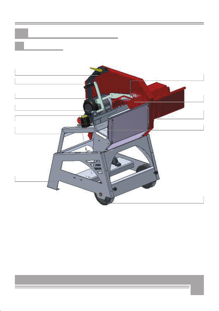
Upper saw-blade
Wheels
Log hold-down
Saw blade
2. MACHINE OVERVIEW
Handling grip
2.1 Cross-cut saw 600
w. electric motor, 230 / 400V
Motor
On/Off Switch
Steel stand
Timber carriage
- extension
Crank lever f. motor carrier
Crank handle f. log clamp
Timber carriage

6
1. . Notice Warning
„Before setting-up, servicing, maintaining and clea-
ning the machine, disengage power and stop the
engine. Lock the tool and secure it against acciden-
tal start.“"
This is to remind the operator that maintenance and cleaning proce-
dures may only be performed with the power off and all moving parts
strictly secured against accidental start. WARNING : watch out, the
blade may take a few minuted to come to a complete stop! Wait till it
stops before accessing the unit in any way.
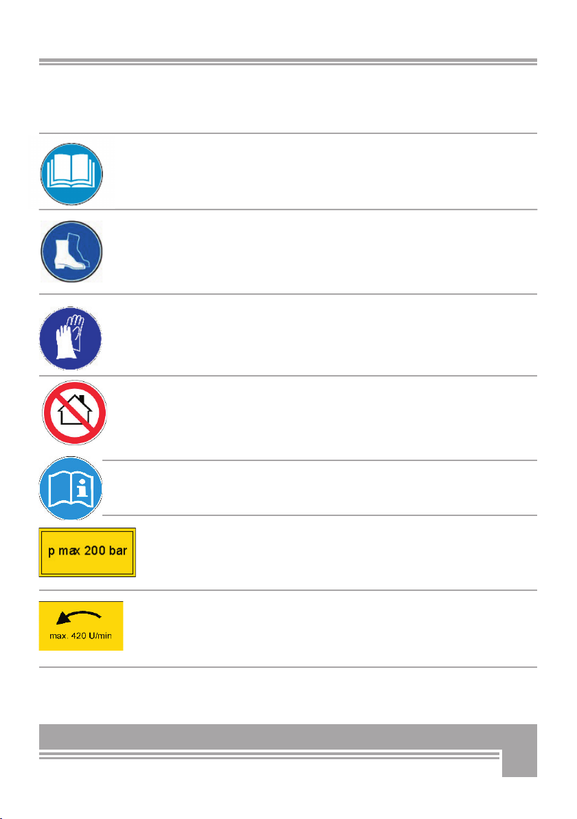
2. Notice Warning
„Eyes and hearing protection is mandatory
Loud noise can cause impairment or loss of hearing, wear a suitable
protective device such as ear plugs or goggles.
3. Pictogram „Check direction of motor revolutions“
This pictogram shows the must-direction of motor revolutions.
4. Safety-alert symbol“
Read, understand, and follow all instructions in this manual and on
the machine before starting!
5. Identifi cation label“
This label shows the company details of the manufacturer and the
main technical data of machine.
6. “BGU-Maschinen“ Manufacturer’s logo
3. SAFETY PICTOGRAMS AND WARNING
7
7. Notice Warning“
Always familiarize with the contents of this manual before setup.”
Read, understand, and follow all instructions in this manual and on
the machine before starting!
8. Safety decal “WARNING Always wear safety shoes“
9. Safety decal “WARNING! Always wear safety
gloves”
10. Notice Warning
“Never run the machine indoors” inside a closed area. The exhaust fu-
mes are toxic!
11. Personal protection sign „Before operating read
operator‘s manual and safety instructions!“
12. Machine safety label „p max 200 bar“
Maximum operating pressure is 200 bar.
13. Machine safety label „max 420 RPM“
This label shows the max admissible number of PTO shaft revolutions.

8
Strictly perform installation, set-up, maintenance, cleaning and
transportation with the motor switched off and all moving parts
firmly secured against accidental operation. Immediately dis-
connect power off the machine in case of any eventual fault or
trouble.
Users shall strictly comply with these operation, set-up, maintenance,
repair and trouble-shooting instructions in order to assure safe opera-
tion and avoid damages to the equipment. The owner must understand
these instructions and must allow only persons who understand these
instructions and are familiar with the related risks to operate the saw.
The operators assigned to this machine must be familiar with the ap-
plicable occupational safety and health administration rules as well as
applicable transportation rules. Incorrect use of the saw can cause se-
rious injury or death.
No person under school leaving age (18) should operate this saw. Tho-
se who have reached school leaving age but are below the age of 16
may operate a log splitter if supervised by a competent person of 18
years or over. The machine shall be installed and kept in a suitable lo-
cation selected by the customer for safest operation.
The working area around the machine must be kept as clear as possi-
ble from surrounding obstacles. Slippery foundation floors should be
duly treated (do not use saw dust or wood ash for this purpose).
Make sure that the saw stands on a safe stable foundation.
Do not allow within the hazardous zone any unauthorized third or per-
sons who are not familiar with the dangers related to use and opera-
tion of the machine. Allow no bystanders, especially children and pets
in the working area.
● Due and proper illumination of the working site must be provided at
all times.
● The saw blade must be duly sharpened for maximum performance
and no recoil danger. Flash and chips must be removed off.
● Damaged, deformed or buckled blades should not be used.
• A skilled licensed electrician must be asked for any repair of
the electric system!
● Always wear gloves, eye and hear protectors as well as safety work
clothes when handling /operating the machine.
Ensure that a wide but confined area is available around the machine
and ensure maximum working freedom.
● Das Tragen von Sicherheitsschuhen, sowie eng anliegender Kleidung
ist für die Bedienperson erforderlich
● Operators must wear steel toe safety shoes and snug-fitting tear-re-
sistant work cloths.
4. SAFETY

9
● No additional customised protections or tools should be provided on
board of the machine, other than the ones designed and supplied by
the manufacturer.
● Do not apply pressure (for instance by means of a wood stock)
against the blade to make it come to a quicker stop.
● Do not use this machine indoors.
NEVER leave the machine unattended without prior power disconnec-
tion.
● Before leaving the operator‘s station for any reason, stop the ma-
chine, disconnect power and secure the machine against accidental
operation.
4.1 Saw blade, safety rules
The following units come with the following (outer diameter) blades:
OD 600 mm for KS 600
OD 700 mm for KS 700E, KS 700Z and KS 700H
Hard metal blades are set to support a maximum speed of 2700 rpm.
Make sure to comply with this requirement.
All saw blades must be certified to EN 847-1.
Hard metal blades required accure care and maintenance. Make sure
that the blade bits do not ever hit against hard surfaces (for example
concrete floors), which might cause invisible bits damage.
Strictly use sharp blades that are free from any damage or flaw.
Do not ever use worn out blades in need of sharpening. Make sre that
the blade shows good conditions, no damages, no cracks, no buckling
and no missing/broken teeth/bits.
4.2 Mandatory application field
This cross-cut saw is designed and should be used for cutting round
firewood logs only. The manufacturer will consider any other use or
application as “misuse”,
Depending on the variant the machine cutting capacity (timber diam.)
is:
KS 600: 8 - 20 cm [3 - 8 in]
KS 700E/Z/H 8 - approx. 25 cm [3 - approx. 10 in]
PLEASE NOTE: this is a one-man operation machine ONLY.
Lack of compliance with these instructions may lead to
dangerous risks and situations and will completely void
your warranty, in which case the manufacturer will not be
responsible for customers’ claims or resulting damages and/or
injuries.
10
The model variants KS 600-230V, KS 600-400V and KS 700EWK are
ideally recommended for stationary use in your yard, whilst the models
KS 700H and KS 700Z can be conveniently used for firewood produc-
tion straight in the woods.
The models KS 600-230V, KS 600-400V and KS 700E are powered by
electronic braking force control. The electric motor must be connec-
ted to a 16-Amp EC power outlet. In case of alternated power (AC)
230V supplies please make sure to use power cords with a section of
2.5 mm2 [0.0039 in2]. These are normally available on the market as
3x2.5 cables. Power supply is controlled by means of a simple switch/
plug combination.
Make sure the length of the power cord does not exceed 10 m [32 ft].
The model KS 700H is powered from the tractor hydraulics. It supplied
with two hydraulic hoses that must be attached your tractor hydraulics
for saw operation. When attaching and connecting the hydraulic hoses,
remember: to check that they are fit properly both on machine and
tractor side;
Attach he red end of the hose to the pressure side and the blue end to
the return flow side.
If you are operating the saw a stationary machine on a yard, you may
also power it by means of any hydraulic power generator.
The KS 700H variant is additionally equipped with 3 point linkage.
A rugged all steel construction assures longest machine life to all vari-
ants at any operating condition.
Attach models KS 700Z directly to power take off on your tractor using
a PTO driveline.
Press the detent lock inward as you slide the machine shaft onto the
tractor PTO stub shaft. Slide the machine shaft forward far enough to
make sure the detent lock has snapped into the lock position.
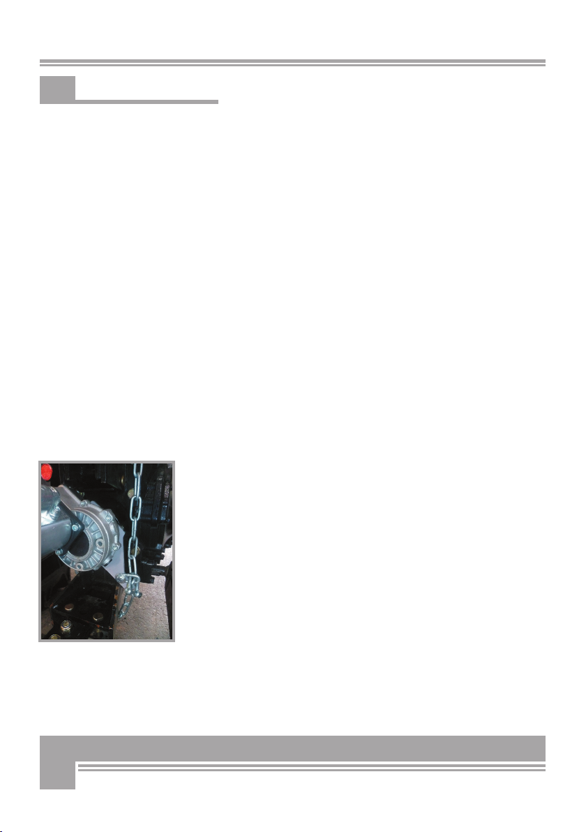
Secure the drive shaft with the special restraining chain to avoid
dangerous twisting.
Make sure that the gearbox (Pos 1, Fig. 1) always matches the position
of the catch on the tractor and faces the direction of driveline revolu-
tion.
Once you successfully connected the saw to a tractor’s 3 point
hitch, and installed the PTO driveline, you are ready to start using it.
Strictly engage the PTO driveline, with the machine/tractor idled. First
off, locate and engage the On/Off saw switch on the left hand side of
the saw.
Then increase the speed of tractor PTO stub up to max. 420 RPM. Now,
the saw is ready for use.
To stop the saw when finished, repeat the same operation in the re-
verse order: slow tractor speed down, switch the saw off, disengage
the PTO, stop the tractor engine, and finally remove the gearbox.
Make sure to disconnect power (switch the tractor off) before perfor-
ming any work (maintenance or repairs) on the saw.
5. OPERATION
Fig.1

11
5.1 Timber carriage extensions
Before starting to operate your saw, make sure to assemble the ex-
tensions of the timber carriage (if you have a KS 600) and
the folding timber carriage (if you have a KS 700E or a KS 700H) on
the right hand side of the blade (carriage extensions are not installed
by the manufacturer to save on transportation space).
For KS 600 models, screw the carriage extensions (1, Fig. 1.1)
using 3 cap square screws.
Fit the screws from the inside face throughout the extension piece
and tighten on the outside face using washer and hex nut (Pos. 2,
Fig.1.1).
For KS 700E, KS 700Z and KS 700H
Bolt the mounting plate (Pos. 3, Fig.2) for the timber carriage to the
steel stand of the saw. Fit the 4
hex screws (and shim underneath them) throughout the plate and
tighten on the back side using a washer and a hex nut for each screw
(Pos. 4, Fig. 2).
5.2 Log-length marks
The marks on the carriage extensions as well as those on the carriage
Pos. 5, Fig. 3) are designed to check, “read” and adjust the length of
the timber pieces to be but off.
Based off of the required log length, timber will have to reach out to
one or the other marking (20cm, 25cm or 33cm) [8, 10, or 13 in].
If you need - just for example - to cut off 50 cm (29 in) long logs,
then you need to push you timber on the carriage and onto the exten-
sion all the way to the outer rim of the extension right hand side.
5
Fig. 3
4
3
Fig. 1.1
1
2
Fig. 2,

12
5.3 First saw cut
Before starting, inspect the machine for evident, visible dama-
ges and unusual conditions.
Make sure the timber carriage is in the initial position (fold
down open) and the locking lever is engaged.
Starting:
Switch the saw on.
If you have an electric version start the machine pressing the
green button of the switch (Pos. 8, Fig. 6).
After switching the machine on (all versions) make sure that the
saw blade gradually starts turning in the right direction. You should
check if the blade runs so that revolutions occur always towards the
operator’s station.
Should rotation be performed in the opposite direction, immediate-
ly stop the machine and use a phase inverter (400V motors only) to
change the plugging polarity of the conductor cable (see Fig. 4):
The plug used for powering the electric versions must be fi tted with a
no-volt release switch designed for rated current up to 30mA.
For KS 700H the control valve lever should be in
7 ON as in Pos. 9, Fig..7).
6 Load your timber on the carriage from your saw left hand side.
Advance timber on the carriage towards the opposite (right) side until
the right end of the timber matches the required log length marking
on the carriage extension.
Depending on timber hardness and diameter, it is recommendable to
clamp the timber using the special hold-down. Fasten the hold-down
grip and pull it down to clamp timber securely on the carriage through
out cutting.
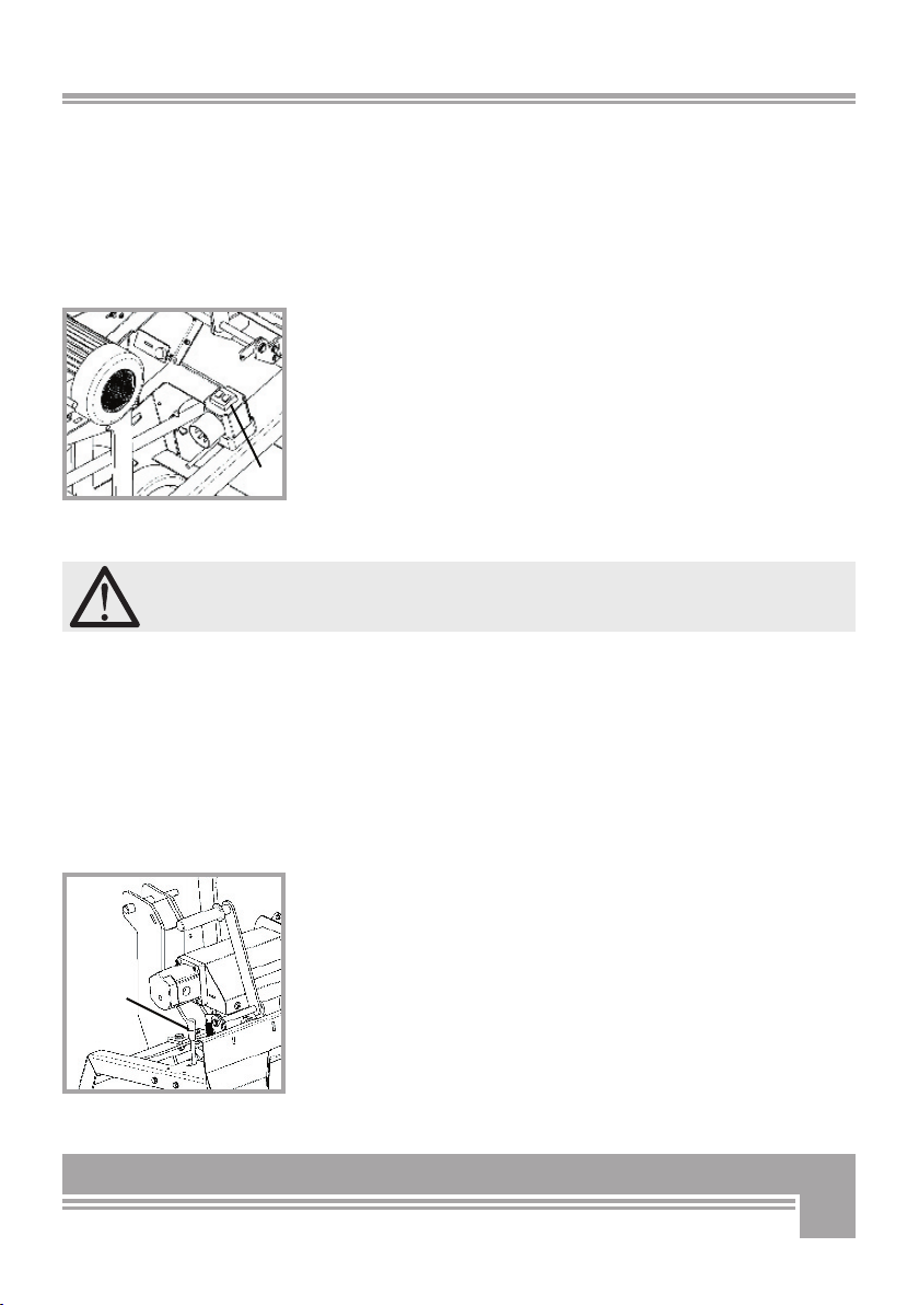
To carry out the fi rst timber cut, fasten the motor carrier crank (Pos.
6, Fig. 5) with your right hand and engage (press down) the crank
handle (Pos. 7 - Fig. 5). This is to release the motor carrier. Now pull
the motor carrier smoothly to the front. When doing so avoid all jerky,
bumpy movements that could lead to risky and dangerous situations.
Caution: Avoid excessive pull force during cutting as this may
slow the blade down and lead to an undesirable jamming of
the saw blade.
Fig.5
Fig. 4 , Phase inverter
7
6
13
As soon as the fi rst log is cut, move the motor carrier back to its ini-
tial position. Make sure to wait for complete cut of the fi rst log before
you advance timber again to the blade. This will prevent risk of inju-
ries for the operators and machine damages that are not covered by
the manufacturer’s warranty.
Strictly cut the next log when the timber has been pushed to the right
all the way to the required log length mark.
Switch the machine off when the job is done.
Stopping:
To stop an electric machine model, use the red button on the
switch (Pos. 8, Fig. 6).
The electric variants are equipped with electronic brake controller that
allows the saw blade to come to a complete stop within 10 seconds
from switching off the machine. The brake controller function permits
the blade to come to a complete stop within a max lag-time of 10 se-
conds after switching the motor off (or disconnecting power supply).
In this case, switch on the machine again to reactivate the electric
motor brake controller.Generation of a humming noise after the bla-
de has come to a complete stop is fully normal and due to motor fan
operation.
DO NOT switch the saw on, while the braking process is
in progress. Restarting during braking is not possible. Wait
approximately 1 minute before restarting the machine
after it was switched off.
The machine is designed for a max number of 10 ON/OFF cyc-
les per hour to avoid damages to electronic braking system.
After you switch the motor off, wait for the blade to come to a
complete stop before unplugging the machine.
Failure of the saw blade to completely stop within 10 minute
time, please stop using the saw immediately and have it over-
hauled!
For KS 700H the control lever (Pos. 9, FIg. 7) should be set
on OFF (=AUS in German).
The model KS 700H is also equipped with electronic brake controller.
The electronic brake controller allows the stopping of blade within max
10 seconds after switching the motor off.
Fig. 6
8
Fig. 7
9
14
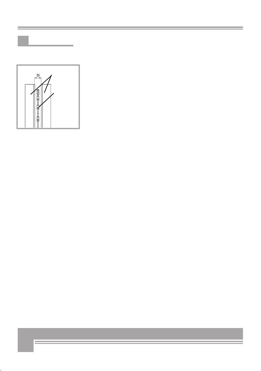
5.4 Saw blade inserts
The maximum spacing between clearance inserts should never be less
than 16 mm.
If the maximum 16 mm spacing between clearance inserts (wood
strips) is reduced because of excessive wear, provide for immediate
replacement of the wooden inserts! (Fig. 8).
The wooden inserts are consumable materials. Therefore, they are not
covered by any warranty (see paragraph 6.4).
Fig. 8
„Max distance between wood inserts“
Wood strips
Saw blade

15
6. REPAIRS AND MAINTENANCE
Make sure that the machine is fully disconnected and all mo-
ving parts are secured before performing any maintenance/
repair work on the machine. Unplug the machine from the po-
wer supply before attempting any cleaning.Immediately di-
sconnect power off the machine in case of any eventual fault
or trouble.
6.1 Ordinary maintenance
Make maintenance a regular part of daily operation. The daily main-
tenance routine needs to include:
• Cleaning of the machine and clearing of all parts from residual wood
debris, chips, dust, bark pieces and eventual other waste.
• Lubrication of all moving parts.
6.2 Cleaning after use
Remove wood chips and saw dust produced and left on the machine
during work. Clean the log carriage assembly removing all wood rest
6.3 Replacing the saw blade
DANGER! BEWARE: pinched hands danger!.
Always wear tear-resistant, safety gloves while handling any cut-
ting tool. Disconnect power and prevent any accidental restart.
(Unplug the machine, disconnect the hydraulic circuit)
.

16
Following instructions apply for safe and proper blade replacement:
● Disconnect the machine from the power supply (stop and unplug or switch
the tractor off and detach the machine from the tractor), and wait for the
blade to have come to a complete stop.
● Open the hood fl ap over the blade by releasing the hex screws (just undo
them a bit. Do not pull them out)
● Fit the fi xation bolt (Pos. 10, Fig. 9) in the special bushing on the steel
stand to secure the blade while undoing the screws.
● Release and undo the fi xation bolt on the blade clamping fl ange
(Pos. 11, Abb. 9).
● Remove the clamping fl ange.
● Pull the old blade off the shaft (make sure to wear tear-resistant
gloves. DANGER!)
● Fit the new blade on the shaft. Note direction of rotation. All tools must al-
ways work against the feed direction that is revolutions must occur towards
the operator’s station.
Saw blade Timber carriage (see Fig. 10 “saw blade position”). Make sure
that the saw blade fi ts tightly on the sits fi rmly on the fi xed fl ange hub!
● Mount the locking fl ange back on the blade shaft minding the right
position of the feather-key in the fl ange.
● Tighten fi xation bolt on the fl ange. BEWARE: when assembling the new
blade make sure to install the hardware in the right order, that it: saw blade,
external saw blade clamping fl ange, washer, fi xation screw.
● Remove the fi xation bolt
● Fit the blade hood in the original position and secure it by tightening all
screw
● If you have a KS 700Z: make sure to check the hydraulic oil level in the
machine before each new use, and every once in a while. Accurately avoid
contaminating the tank with dirt, wood chips, or saw dust.
Make sure that the machine never runs without oil or with a low oil level.
When this happens, air is likely to reach inside the hydraulic loop. Failure to
maintain due oil level may cause poor running and irregular saw operation
(very rough, jerky motions) as well as major pump damages. Please schedu-
le your fi rst oil change after approximately 50 operation hours and at least
once a year from then on. Always replace the oil fi lter with each completely
new oil fi ll. Recommended oil types:
DEA HD B 46, Shell Tellus 10-46, Esso Nuto H 46
Monitor your saw cut quality always. A dull saw blade will immedi-
ately turn into a poor cut quality. In this case seek professional ser-
vice to regrind. Do not regrind worn out blades yourself. Always ask
for skilled help.
6.4 Consumables
KS 600:
Saw blade (Code No. 95004 HM) -
Wood strip, left side (Code No. 29711)
Wood strip, right side (Code No. 29712)
KS 700:
Saw blade (Code No. 95021 HM)
Wood strip, left side (Code No. 29713)
Wood strip, right side (Code No. 29714)
Hydraulic hoses (please replace them after approx. every 4 years).
CONSUMABLES ARE NO WARRANTY PARTS!!!
Fig. 10
Position of the saw
blade“
Sägeblatt
Holz-
aufl age
Fig.9
10
11

17
7. TRANSPORTATION
These cross-cutting saws are light equipment that can be
easily moved on short-distance by means of two caster wheels and an ergono-
mic, comfortable grip handle located on the stand on the opposite side as the
timber carriage. In order to avoid infringement of the clearance area around
the machine, the grip handle can be pulled in/out.
Secure the grip handle with its linchpin (Pos. 12, Fig. 11) to prevent the handle
from accidentally sliding back in while pushing the machine away.
Simply fasten the grip (Pos. 13, Fig. 11) and lift the saw for safe and rapid
hauling of the machine. For safety reasons the grip handle should remain re-
tracted during work to avoid risk of tripping or entanglement. Just pull it out
when you need it to move /handle the machine around.
Remember to lock the carriage before attempting any even short-distance
handling of the machine. To lock the carriage fl ip it to the front and secure
it with the clevis pin (Pos. 14, Fig.12). Fit the clevis pin into the holes in the
stays of the motor carrier and through the bushing welded on the steel stand.
Use the cotters (Pos. 15, Fig. 12) to secure le clevis pins against accidental
slipping out and release.
If you have a KS700E/ Z or a KS700H fold up and secure the timber carriage.
7.1 Transporting the machine (for KS 700H only) on a three-point linkage
Attach the machine to a 3-point hitch (Pos. 13, Cat. I or II) of a tractor
(or another equivalent vehicle), and comply with the following instruc-
tions:
Should the dimensions of the machine hide any of the travel signs and
illumination systems on board of your tractor (rear/head lights, rear
travel lights, stop lights, turn indicators etc...), you must provide for
the same signs and lights on the machine is order to travel on public
roads.
The same applies for eventual other tools and ancillary equipment in-
fringing the tractor profi le by 1 meter in the back and by 40 cm on
the sides. In this latter case, side lights must be provided in the front.
Make sure to apply suitable warning sings (white/red) as per DIN Stan-
dards 11300 to warn about protruding obstacles likely to endanger the
nearby traffi c. For more updated information please consult StVO. If
transporting by attachment to a three-point hitch of a farming tractor,
make sure to provide suitable front ballast for increased steering per-
formance, if required in accordance with the tractor load chart.
Do not exceed the max transportation speed of 30 km/h.
12
Fig.11
13
Fig. 12
14 15
Fig. 13

18
8. DECOMMISSIONING AND DISPOSAL
When the saw is fully obsolete and cannot be of any longer use, it
should be duly dismounted ahead of discarding. Certain components
need deactivation and dismantling in order to assure that no further
use is made by other parties and that no worn out parts are recycled
for other applications.
During dismantle be alert for possible recyclable materials and compo-
nents that belong to differentiated waste collection procedures applica-
ble in your country.
The manufacturer is not liable and undertakes no responsibility for
personal injuries or damages that may result from the recycling of
worn out machine parts and eventual re-use in other applications dif-
ferent than originally stated in this manual.
Dismantling procedure:
Take good note please: each and every dismantling task must be per-
formed by authorized service centres or trained skilled staff only!
● Lock all moving parts of the mill and pull the machine
● Release all pressure out of the hydraulic hoses and drain all hydrau-
lic oil out
● Hydraulic oil is highly polluting and must be safely disposed of
● Deliver each single component only to authorized waste manage-
ment facilities
● Remove rubber and plastic parts from the machine that must be se-
parately disposed of.
Deactivated, clamped moving/driving parts and components are of no
further risk and danger.
Electric components must be separately disposed to avoid substantial
environmental threat. In the event of fire on the electric deployment
system of the machine, use of an explosion proof extinguish system is
required (for example powder fire extinguishers).

19
9. TECHNICAL SPECIFICATIONS
Technical Data U/Mes. Cross-cut
saw 600
Cross-cut
saw 600
Cross-cut
saw 700E
Cross-
cut saw
700H
Cross-cut
saw KS
700Z
Max. timber diameter mm 200 200 250 250 250
Saw blade diameter mm 600/30 600/30 700/30 700/30 70030
Output power P1 S6
40% ED
kW 3,0
(60%ED)
4,0 5,2 -
Tractor power require-
ment
kW/PS - - - 10 kW/
13,6
10 kW/
13,6
Saw blade velocity U/min 1280 1380 1380 1750 1750
Voltage U V230 400 400 -
Current I A 13,5 6,8 9,0 -
Frequency Hz 50 50 50 -
Inlet fuses A 16 slow-
blow
K 20 slow-
blow
16 slow-
blow
-
No volt release switch ja ja ja -
Safety thermal overload
switch
ja ja ja -
Operating pressure bar - - - max.200
Flow rate l/min - - - max.30
Weight kg 140 140 195 202 250
Max number of driveli-
ne rev.
420
Operating Dimensions
Length mm 1124 1124 1589 1677 1677
Depth mm 967 967 1104 1154 1154
Height mm 1354 1354 1431 1432 1432
Transport Dimensions
Length 782 782 947 1035 1035
Depth 967 967 1104 1104 1104
Height 1354 1354 1435 1435 1435

20
9.1 Noise emissions
Noise emissions were measured in accordance with the European di-
rectives for the measurement of noise emissions on the workplace.
The measurement was performed by external authorized certification
bodies in compliance with the applicable standards based on applica-
ble rules for agricultural and forestry equipment. The detected noise
level was.
Measurement on the machine front edge at 1600 mm height and
400mm away from the blade on the right, while processing beech
wood in the size of 80+/-5% of the admissible diameter as in the
user’s manual.
Detected noise level:
No load Full load
Saw model 700E / 700H 82 db(A) 96 db(A)
Saw model 600 82 db(A) 96 db(A)
When working with BGU wood processor, use ears protectors!
The above mentioned values are emission measurements and may not
be therefore assumed as for a safe work environment. Although there
is a relationship between noise emission and immission levels, this is
not a sufficient basis to determine the extent of on-site required pro-
tection. There are a lot of other factors that can influence site work
and risk of injuries and namely: the actual site/buildings configura-
tion, the concomitant presence of other noise sources (for instance
other machines performing other works in the neighbourhood) etc...
The factors applied for determining safety of a workplace may also ve-
ry from one country to the other. We are reporting here the noise va-
lues detected in the facility of the manufacturer on order to allow the
user performing a better evaluation of the possible risk/disturbance.
This manual suits for next models
2
Table of contents
Other BGU Saw manuals


Popular Saw manuals by other brands

Diamond Tech International
Diamond Tech International Power Miter II Operation manual

Black & Decker
Black & Decker BDRS1800 instruction manual

Makita
Makita 2712 instruction manual

Scantool
Scantool SC 125V user manual

Bosch
Bosch Professional GKS 130 Original instructions

Schwamborn
Schwamborn FBS P operating instructions


