BGU BBS 500 B User manual

page 1 / 51
Insructions manual CTR 520 GX 2014-05-05
INSTRUCTIONS FOR USE
THE LOG BAND SAW
BBS 500 B
Südharzer Maschinenbau GmbH Helmestraße 94 ∙ 99734
Nordhausen/Harz Zentrale: 03631/6297-0 ∙ 7-111 Internet:
www.bgu-maschinen.de e-mail: [email protected]

page 2 / 51
Insructions manual CTR 520 GX 2014-05-05

page 3 / 49
Insructions manual BBS 500 B 2014-05-05
0. Generally ............................................................4
0.1.Safety regulations.................................................. 4
0.2.Scope of use / Designated use.............................. 6
0.3. Unacceptable ways of using.................................. 6
0.4.Requirements for operational staff ........................ 6
0.5. Requirements for machine - security devices........ 7
0.6.Safety guards ........................................................ 7
1. Shipping, handling and storage.......................8
1.1.Surface protection ................................................. 9
1.2.Packing.................................................................. 9
1.3.Dismantling/ repacking .......................................... 9
1.4.Disposal................................................................. 9
2. Installation........................................................10
2.1.Required surface ................................................. 10
2.1.1. Danger zone, operator´s station....................... 11
2.2. Location of machine ............................................ 11
2.3.Fuel...................................................................... 11
3. The machine data ............................................12
3.1. Description of the machinery............................... 13
3.3. Technical data...................................................... 13
4. Putting into operation .....................................16
4.1. Safety check........................................................ 16
4.2. Parking zone........................................................ 16
4.3. The rst cut.......................................................... 16
4.4. Setting up and the clamping of material .............. 17
4.4.1.Angular rests .................................................... 17
4.4.2.Material clamps ................................................ 17
4.5.Residual risks and risk situations ........................ 18
5. Description of the machine and its adjustment........ 20
5.1.Arm................................................................................... 20
5.1.1. Adjustment of a saw band ............................................ 20
5.1.2. Replacing of the saw band ............................................ 22
5.1.3. Cooling, cleaning of the saw band................................. 22
5.1.4. The sliding guide bar of the saw band........................... 22
5.1.5. Replacing of the tensioning wheel V-belt ...................... 23
5.1.6. Tensioning of the drive wheel V-belt ............................. 23
5.1.7 Adjustment of the clutch and brake, belt replacement.... 23
5.2. The drive........................................................................... 24
5.2.1.Engine ........................................................................... 24
5.3. Setting the cut thickness .................................................. 25
5.3.1. Measurement of the cut height ..................................... 25
5.3.2. Thickness setting using the dial..................................... 25
6. Preventive maintenance of machine ........................ 26
6.1.Maintenance and inspection............................................. 26
6.2. Lubricating plan ................................................................ 27
7. Saw bands.................................................................... 27
7.1.Safety regulations............................................................. 27
7.2.Instructions for tool operation ........................................... 27
7.3. Troubleshooting when using the saw bands .................... 28
8. Faults - causes and remedies .................................... 29
9. Circuit diagram ............................................................ 30
9.1. Circuit diagram for BBS 500 B ...................................... 30
9.2.List of electrical components of BBS 500 B .................. 30
10. Machine accessories ................................................ 31
11. ............. 32
12. Assembly instructions.............................................. 33
13. Spare parts................................................................. 38
Dear Customer,
we thank you that you have decided to purchase our product, and we wish you much success with it. To get the
machine without problems served, please pay careful attention to the following instructions.
Manufacturer: Südharzer Maschinenbau GmbH
Helmestraße 94
99734 Nordhausen
Germany
© Copyright 2013 All rights, especially the right for copying, distribution and translation reserved. No part of
this manual must not , without the written permission of Südharzer Maschinenbau GmbH in any form (print,
photocopy, scanning, microfilm or any other method), be reproduced or with use of electronic systems recorded,
processed, copied or distributed.
These instructions correspond to the current technical specifications. Any technical changes, misprints and differences
in pictures are subject to change without notice. In case the machine will be sold to a third party, provide it with
this guide..
Content
ORIGINAL INSTRUCTIONS FOR USE ver. 05/05/2014

page 4 / 49
Insructions manual BBS 500 B 2014-05-05
0. Generally
This manual is intended to provide you information and help you to become familiar with the log band saw of the
BGU maschine company and utilizing its potential use by its determination. The operating instructions contain
important instructions how to operate the machine safely, professionally and economically. Its observance will avoid
risks, reduce repair costs and downtime and increase reliability and service life. Instruction manual provides
guidance based on the current national regulations for accident prevention and environmental protection. The
operating instructions must be in place to use the machine still available. Operating instructions must be read
and applied by anyone who is responsible for the installation, transport and storage, use, operation,
maintenance and disposal of equipment. In addition to the manual and binding rules applicable in the user
country and the place of use for the prevention of accidents must be observed and approved rules for safe and
professional work.
putting the machine into operation. The manufacturer is not liable for damages resulting from
disregard of operating instructions and safety instructions. At the same time the buyer loses
Warranty Card - service
The Warranty Card is a separate attachment of the operating instructions
The warranty period : see warranty card
Conditions for maintaining liability claims
• Transporting and storing the machine according to the manual
• Use and maintenance of equipment according to the manual
• The use of prescribed operational llings
The warranty does not apply to:
• Violent and mechanical damage to the machine by an intervention of consumers or other persons
• Unavoidable event (natural disaster)
• Damage to the machine during transport
• Storage or placement the machine in a humid, chemical, or otherwise unsuitable environment
• Wear parts - band saw guides, V-Belts of impellers, band saw blade
or by post to the address: see warranty card.
Notications to consumers:
The seller is obliged immediately to issue to the consumer when purchasing, the product warranty card which must
be completed correctly and legibly and stamped by the dealer signature and date of purchase. The seller must inform
the buyer informatively to be familiar with the product, its use and handling.
The data required for the application of the warranty (post warranty) repairs:
• Type of machine
• The warranty card number (the same as the serial number of the machine)
• Date of issue of the warranty certicate
0.1. Safety regulations
The machine is designed using state of the art and the approved safety rules. However, it may occur when using a
serious threat to the health of users or third parties or to adverse effects on the machine or other property values. In
order to avoid these threats as much as possible, it is essential to ensure the safety notes in the operating instructions.
These safety instructions the person has to read and understood before starting up the machine. Failure to follow
these instructions can result in serious injury and property damage!

page 5 / 49
Insructions manual BBS 500 B 2014-05-05
Particularly important points in this manual that relate to safety are highlighted with
Warning label - danger of compression, shear, impact
Warning label - danger of cuts or cut off, snatching, draw in
Warning label - Danger caused by a sawdust scattering
Warning label - Danger caused by falling objects or their ejection
Warning label - Danger - hot surface
Label TOTAL STOP - Use when necessary equipment emergency stop
Label of the need to use protective equipment - Eye and Ear Protectors
Label of the need to use protective equipment - Protective gloves, boots
Label of the machine safe handling - Place of suspension
understand its contents

page 6 / 49
Insructions manual BBS 500 B 2014-05-05
0.2. Scope of use / Designated use
Log Band Saw is designed primarily for the logs initial processing. It is intended solely for cutting wood materials,
whether soft, hard, dry, raw or frozen in length according to the machine design. The use according to specications
includes compliance with the operating instructions and compliance with inspection and maintenance conditions.
0.3. Unacceptable ways of using
Any other use dened in Chapter. 0.2. is understood as the use of inappropriate determination. For damages caused
by this way the manufacturer is not liable. Risk is borne by the user.
0.4. Requirements for operational staff
The machine operator is responsible for the overall safe operation of the machine and
compliance with safety and technical instructions given in this manual.
The machine may only be operated if it is in the perfect technical safety
User is obliged to at least once per shift to check the machine outside recognizable damages or defects (see Chapter
6). The resulting defects and damage to the protective devices, and machines behavioral changes that threaten the
safety, report immediately to the supervisor. Switch off the machine and secure against restarting. Wait for decision
on the repair and reinstatement of your machine.
When operating the machine, not remove, relocate, shut it down or modify any safety devices. Warranty claims are
otherwise ineffective! If during the repair or maintenance must be some safety devices removed, turn the ignition
switch, activate TOTAL STOP button and close the fuel supply.
• Remove when working loose clothing and cover long hair
• Ensure that other persons were away from the belt at least 5 m, protect them against ying sawdust and dangers
in the event that the saw band should have broken
• All the people that help you must be familiar with all safety rules
• Safety rules must be placed at the workplace on a clearly visible place
• Keep your hands away from the saw band, never adjust any saw band when the engine is running. Before you
manipulate with the saw band, turn off the motor and secure it against restarting!
appropriate protective equipment (eyewear, hearing, gloves, safety shoes
with steel toe).

page 7 / 49
Insructions manual BBS 500 B 2014-05-05
0.5. Requirements for machine - security devices
Before opening the protective device, wait until the saw band is at rest.
Shutting down the machine in case of an emergency with the button STOP TOTAL.
New start-up is possible only after the removal of the emergency and manual
override of the button by its pulling or turning.
machine and tool operation and deceleration, prohibited.
In the danger zone shall be any unauthorized person. The danger zone must also be free of foreign objects and the
ground must be at to prevent tripping.
Parking zone (see the chapter 4.2)
The parking zone is used to a safe shut down of the traversing bridge with a band saw arm.
• You provide the handling of the cut material (niggering of log, alignment, clamping, rotating, removing of timber)
• You provide the setting of the movable bar of the saw band (if the machine is not equipped with a motorized bar*)
• You provide the setting of the saw band cooling
• You provide the cleaning or maintaining the machine
• You provide the cleaning around the machine
• The machine operator leaving the workplace
0.6. Safety guards
The log band saw is the cutting machine equipped with a cutting saw band. To perform this process, the teeth of the
saw band must penetrate into the work piece in the machining area. Safety guards against the contact with the saw
band can therefore be installed only outside the machining area. Other safety guards protect against a contact with
dangerous parts of the drive or hot engine parts..

page 8 / 49
Insructions manual BBS 500 B 2014-05-05
• The safety arm cover (impellers of the saw band
with belt) is secured by two screws in captive design. If
the safety cover is not closed and both screws are not
tightened, it is not permitted to run the engine. Safety
covers are tted with hinges, in service operations is
not necessary to disassemble.
• Safety guards of the saw band drive (pulleys and
belts) . Guards must be removed during tensioning,
exchange and check of V-belts and the brake
adjusting.
• The safety guard of the band outside the machining
area on the moving guide bar. During service
operations is not necessary to remove the guard.
Safety guards are allowed to dismount only when the engine is not running and the
guards and after testing their safety functions.
1. Shipping, handling and storage
The machine is dispatched dismantled and packed on a wooden pallet. If, with the machine whose the basic length is
4500 mm, more than one extension section of length 2225 mm is supplied, these extension sections are stored on other
pallet. The machine is supplied with one saw band mounted on the machine, the oil lling of the engine and without
fuel. During transport must be taken appropriate measures to prevent damage from moisture, vibrations and shocks.
After installing the basic and extension section(-s) at the site of use, the bridge with the arm is lifted by crane and
placed gently on the basic section.
Traversing bridge can only be lifted by crane.
When the traversing bridge is attached to the original manufacturer pallet, it can be transported on
a pallet trolley.
SAFETY GUARD
OF ARM
SAFETY GUARD GRIP
BOLTS
BELTS GUARDS
BOLTS
THE BAND GUARD

page 9 / 49
Insructions manual BBS 500 B 2014-05-05
Scope of delivery:
• The basic machine (see chapter 3.2)
• Optional equipment according to the order (extension
section)
• 1 saw band (installed)
• Instructions for use
1.1. Surface protection
Machine components are protected against corrosion
with powder coat or base colour and two-component
polyurethane varnish. Sliding surfaces are coated with
anti-rust oil. Other components and machine parts are
nished with zinc.
Against weather influences during the transport, the
machine parts are packed in a stretch foil. Upon customer
request according the type of expedition, the machine
can be in casing or overseas box.
1. Set all machine parts to the basic position, the arm must be
2. Empty and clean the container of coolant
3. Clean machine
4. Drain the gasoline and treat the engine according to the user manual of the engine - page 13:
Engine laying
5. Coat the sliding surfaces of machine with anti-rust oil
6. Secure the bridge travel of the arm for transport
8. Enclose accessories
1.4. Disposal
After the nal removal from service, the machine is disposed according to the provisions in force in the respective
country. We recommend contacting a company specialized in disposal.
BRIDGE SUSPENSION
THROUGH THE HOLES
IN STIFFENERS
BRIDGE
FRAME
LONGERONS
BOARDING
OF LONGERONS
PALLET
BOXES
OF SMALL PARTS
FRAME
CROSSMEMBERS

page 10 / 49
Insructions manual BBS 500 B 2014-05-05
2. Installation
Installation of the machine is done by customer itself according to the „Mounting instructions“, see Annex 1. Installation
can be performed also by professional service - contact your dealer or manufacturer.
2.1. Required surface
The machine can be installed on any convenient at oor. For optimum machine performance and achievement of
maximum accuracy in cutting, it is recommended to install the machine on a at concrete surface or on concrete slabs
under shelter. Any other basis is necessary to consult the manufacturer. Due to the drive by gasoline engine is not
permitted to operate with in conned spaces.
Recommendations / preconditions:
• Plan to have enough space for the ow of material, material removal and machine maintenance, see Danger zone
• Post of the saw and staff must be at, clean and shall not impair the operation and activities of the operator
• Install lifting equipment for heavy materials
• Provide good lighting in the workplace
For the spatial arrangement of the machine, observe all applicable standards and sanitary regulations of the airspace
in the workplace. The deployment of machines must eliminate threats to other employees from the operation in the
event of the tool accident, by thrown material to be cut due to the insufcient clamping, breakage of the saw band
and the like.
BBS 500
The dimensions marked for K are the anchor holes dimensions of the machine basic section, holes ø11 mm.
BBS 50
The dimensions marked for K are the anchor holes dimensions of the machine basic section, holes ø 11 mm.
800 K800 K650 K800 K800 K396
698 K
275
4875
1650
565
254 800 K800 K396
225
698 K

page 11 / 49
Insructions manual BBS 500 B 2014-05-05
Danger zone is within 2.5 of each side of the machine. In the danger zone must not be any unauthorized person. The
danger zone must also be free of foreign objects and the ground must be at to prevent tripping.
the following features::
The machine operator must, when running the saw band, be located at the control
panel only.
2.2. Location of machine
The machine can be operated at ambient air temperature of + 5 ° C to + 40 ° C. The average air temperature must
never exceed 24 hours + 35 ° C. Relative humidity from 30% to 95%, to an altitude of 1000 m. In the case of higher
altitudes consult the use with the machine manufacturer. At temperatures lower than +5 ° C, replace conventional
refrigerants for the media which operate at the appropriate temperatures.
2.3. Fuel
Used engine is approved to operate on unleaded gasoline with an octane rating of 86 or higher.
burns or seriously injure. Turn off the engine, near must not be resources
Gasoline can damage varnishes and some plastics. Be careful not to spill gasoline. Damage caused by spilled gasoline
is not covered under warranty.
250
250 250
250
OPERATOR´S
PLACE

page 12 / 49
Insructions manual BBS 500 B 2014-05-05
3. The machine data
THICKNESS
GAUGE
LIFT HANDLE
ENGINE
HEIGHT INDICATOR
CLUTCH AND
BRAKE LEVER
COOLING
BASIC SECTION
ANGULAR REST
CLAMP
ADJUSTABLE LEG
FRAME CLUTCH
ARM
TENSIONER
SLIDE BAR
THROTTLE
LEVER
HANDLE
TOTAL STOP
TRAVERSING BRIDGE

page 13 / 49
Insructions manual BBS 500 B 2014-05-05
3.1. Description of the machinery
The machine is designed in a modular way which allows easy replacement or adjustment of all major technology units
and their individual parts. The machine consists of three basic parts:
The basis of each machine is a basic section to which you can connect, according the required cut length, the
extension sections. Basic and extension sections are tted with xed log loading surfaces, clamps of material and
angular adjustable rests.
On traversing sections moves the bridge of the band saw arm. The movement of the bridge on sections is manual -
pushing. On the bridge is placed the arm of the saw band which is placed on pulleys in order to move up and down.
The vertical movement of the arm is secured by a chain drive and worm gear. The movement of the arm is manually
operated by handle with arrestment. Precise adjustment of the arm height allows a circular scale indicator.
On the right side of the arm is a drive wheel of the saw band, driven by a spark ignition engine through a two-stage
belt gear. The clutch function represents the belt tension by the move of the entire motor, and a quick stop of the saw
band is secured by the brake shoe acting on the pulley. Position of the drive wheel pin is adjustable. On the left side
is located a tension wheel system. The movable body of the tensioning system moves in the cast iron guiding. Both
wheels are made of light alloy. In the circumference of the wheel is a machine cut groove for V-belt which forms the
interface between the wheel and the saw band. When cutting, the saw band is guided on both sides with guides of
hard metal.
3.2. Machine design
The basic design of the machine is possible, for an extra fee, to supply with special accessories.
The basic version:
Traversing frame, with length of 4.5 meters can cut logs of a maximum 3.45 m, is equipped with three sets of angular
rests and clamps. Material handling and clamping is manual.
Special accessories:
Extending sections: the total length of 2.25 m, it extends the cutting length of the basic section by 2.25 m, contains
1x angular rest and 1x clamp. The number of extending sections is not limited.
Angular rest with clamp: The basic version can be tted with a maximum of 6 angular rests with the clamp. Each
extension section can be equipped with a maximum of 3 angular rests with clamp.
3.3. Technical data BBS 500 B
1 Max. diameter of the log 550 mm
2 Max. width of the beam (board) 530 mm
3 Max. stroke of the saw band 480 mm
4 Min. height of the saw band above the table 25 mm
5 Max. passage of the arm 200 mm
6 The cutting length of the basic section 3,45 m
7 The length of the extending section 2,25 m
8 Max. cutting length unlimited
9 Min. cutting length 0,75 m
10 The engine of the saw band 8,7 kW
11 Diameter of impellers 400 mm
12 Width of impellers 25 mm
13 Dimensions of the saw band 3340 × 27 × 0,9 mm
14 Cutting loss 1,5 - 2,2 mm
15 Saw band speed 15 m/s
16 Machine width - max. 1660 mm
17 Machine height min. - max. 1500 - 1600 mm
18 The length of the basic version incl. control panel 4,9 m
19 Weight of the basic version incl. accessories 370 kg
20 The length of the extending section 2.25 m
21 Weight of extension 73 kg
22 Working table height from oor 235 - 260 mm

page 14 / 49
Insructions manual BBS 500 B 2014-05-05
17
(MAX)
16
22 3
5
1
2
4
17
(MIN)
11

page 15 / 49
Insructions manual BBS 500 B 2014-05-05
The cutting lengths of the machine
To use the minimum length of the cut is necessary to place the clamp so that it is possible to clamp a log by two
clamps. Each extending section increases cutting length by 2.25 m
The noise measurements were made at machine steady state . During the operating state of a load, the most
commonly used technology process was measured. During operating statuses with the technology, the noise levels
were measured at a work station.
Measured according to EN ISO 3746:2011
The measured value exceeds the value specied in Decree 176/2008, Article 1.7.4.2. point, therefore it is necessary
during operation to use hearing protection devices and monitor the noise characteristics of the device.
The values of the measured noise level of the machine may vary according to the type of material and technology
used. These values are emission levels and may not represent the safe working level. Although the correlation
between emission levels and exposure levels, these values can not be used to reliably determine whether or not
further action is required. Factors that affect the actual level of exposure include the characteristics of the work area,
other sources of noise, etc., such as the number of machines and other adjacent processes. Maximum permissible
levels of exposure may also be different in different countries. This information is intended to serve users as better
tools for hazards and risk assessment.
Electromagnetic radiation
With regard to the electromagnetic field, the device meets all requirements of the standard EN 12198-1 + A1: 2008.
750
345
The measured values
Machine sound power LWA 109,8 dB (A)
Sound pressure LPA 92,3±3 dB (A)

page 16 / 49
Insructions manual BBS 500 B 2014-05-05
4. Putting into operation
It‘s all as for the technical safety in perfect condition?
Are all protective devices correctly installed?
• Check the position of the clamps and angular rests to be out of the cutting path of the saw band
• Check the positions of the cut material to prevent its release during the cutting or its thrust to the traversing bridge
• The machine is now ready for operation
The parking zone is used to a safe shut down of the traversing bridge with a band saw arm.
• You provide the handling of the cut material (niggering of log, alignment, clamping, rotating, removing of timber)
• You set the sliding guide rail of the saw band
• You set the cooling of the saw band
• You provide cleaning or maintaining the machine
• You clean around the machine.
• The machine operator leaves the workplace
1. Make sure that the TOTAL STOP button is released, the band covers are closed and the band is properly tensioned.
2. Make sure that traversing bridge is in the parking zone at the beginning of the machine track
3. Set up the angular rests to the vertical position
4. Load up the log on a saw table
a) using suitable machinery - such as a forklift truck
b) using the track for rolling up the log * and levers for rolling up the log *
- place the two parts for rolling up the log in suitable position with regard to the length of the log
- roll up the log, using a lever for turning the log, so that it has always been secured with the track latch
before changing the position of the lever
5. According to the diameter of the log, set the angular rests to the appropriate position
6. Clamp the log by the material clamps
7. Visually inspect if the position of the log, angular rests and clamps allows you to make the cut
8. Adjust the height of the saw band
9. Adjust the sliding guide bar to the suitable position according to the diameter of the log
10. Make sure that the clutch lever and the brake is in the position „braked
11. Open the fuel supply, turn the engine switch to position 1, and when the engine is cold turn the choke.
12. Pull the starter handle cable to start the motor. If necessary starting again, wait until the motor stops.
13. Adjust coolant ow
PARKING
ZONE
OPERATOR´S
PLACE

page 17 / 49
Insructions manual BBS 500 B 2014-05-05
14. If the choke was turned on, you can, after stabilization of the engine, turn it off.
15.With a throttle lever slightly increase the engine speed and smoothly move the clutch and brake lever to the position
„connected“.
16. Pull the throttle lever to the handle to set the maximum engine speed and smoothly move the band into the material.
17. During the cutting operation observe the machine, possibly the sound changes. If necessary (large knots, larger
width change of the cut), you can adjust the traverse speed - change the speed as smooth as possible, and in the
smallest necessary extent - a sharp change in traverse speed can affect the cut atness,).
18. Once the belt at the end of the log comes out of the wood, release the throttle and clutch lever and brake lever to
the position „stopped“.
19. Lift the saw band above the material being cut off
20. Move the travel bridge cross to the parking zone at the start of the track
21. Remove the cut material from the saw
22. Adjust the height of the band for the next cut
4.4. Setting up and the clamping of material
Any material handling perform only when traversing bridge with a band saw arm is
Before loading a log (logs) on the table, it is necessary the angular rests tilted so that the logs does not fall from the
table. This device is also used for slabing when producing the squared timber. Log clamping is carried out by material
clamps. Clamps can be moved on the machine frame according the length the cut log. The actual log clamping is
performed using the spikes of the clamp that can be adjusted in height by folding clamp arms according to shape
and size of timber.
4.4.1. Angular rests
Serve:
• To prevent rollover of the log via the machine table when loading
• As the rest when clamping
• To create a right angle
Before cutting or traversing a saw bridge, the angular rests must be set in such a position (height)
4.4.2. Material clamps
They are collapsible, allowing their height adjustment. They can be used in two ways:
1. Clamping against angular rests
The wood is pushed by spikes set to the appropriate height to angular rests
2. Clamping against the stop on the frame cross member
Applicable only for prisms
Angular rests are folded and the clamps are adjusted as low as possible
saw band and the guide rollers.
The sliding guide roller of the saw band must be as close as possible to the material being cut. Material must not with
its length exceed the length of the cutting machine.
When loading material on the machine frame store it gently and avoid greater impact - it could cause deformation of
the machine or its displacement.
Check logs before their cutting (stones in the bark, mud, sand, tie pins, etc.). Very dirty logs is necessary, especially
from the side where the saw band get into the log, to get rid of bark or clean (e.g. with a wire brush).
ANGULAR
REST
HANDLE
CLAMP
SPIKE
page 18 / 49
Insructions manual BBS 500 B 2014-05-05
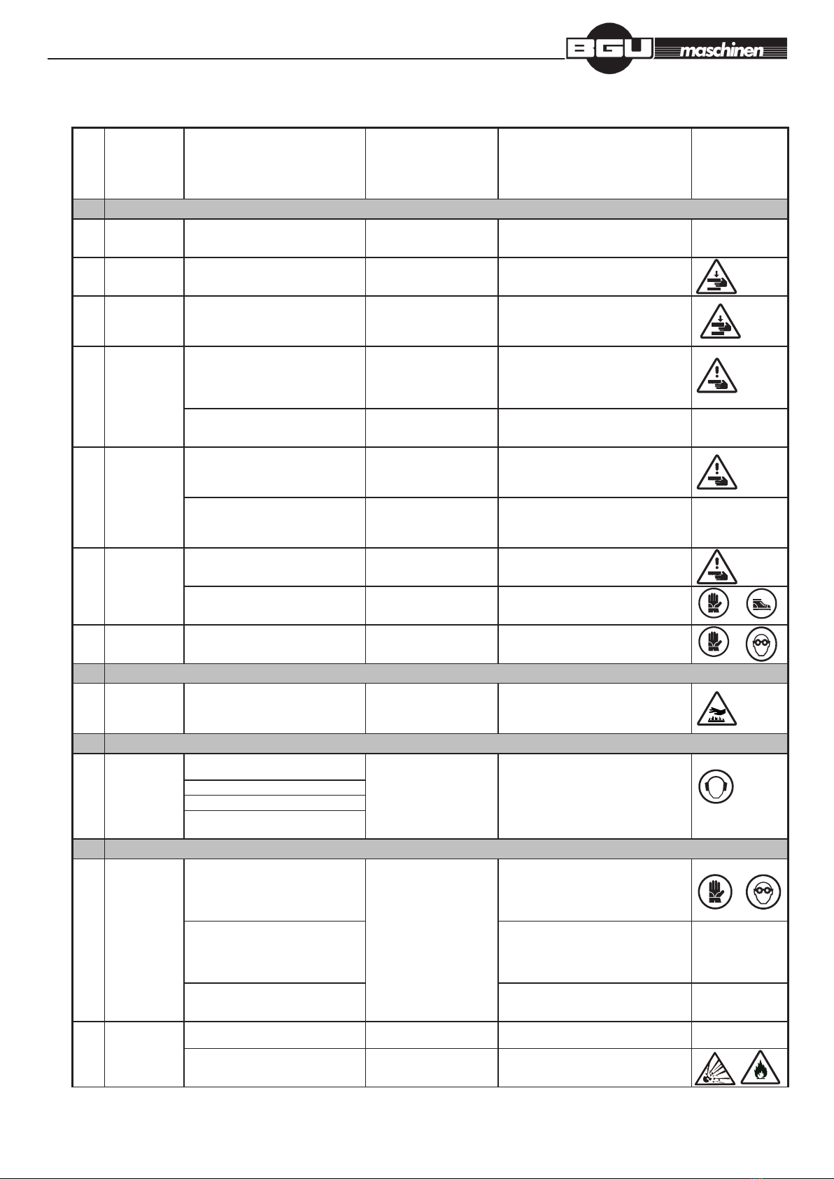
Processed according to standards: Directive 2006/42/EC, NV 176/2008 Coll., EN 1807+ A1: 2010, EN ISO 14121-1:2008
Accor
ding
to
EN
1050
Danger
situations / activities
Dangerous space
(spaces))
Protective measures
(implemented by the designer
/ user)
Safety sign at
machine
1 Mechanical danger
1.1 Compression
danger
Clamping of the cut material during
insertion / modication of the position /
removing material
Between the jaws and
material to be sawn
Warning instructions - use gloves It is not
1.2 Danger of cut Clamping of the cut material during
insertion / modication of the position /
removing material
Between the jaws and
material to be sawn
Warning sign on both ends of the arm
(covering) warnings in the instructions for
use
1.3 Danger of cutting
yourself or
cutting off
The moving of the cutting tool in the
work, machine adjusting, changing
cutting tools, maintenance, repair
For the cutting tool IInstallation of guards outside the cutting
area, warning signs at both ends of the
arm (covering) warnings in the instructions
for use
1.4 Danger of
capturing
Manually operated a cutting tool traverse
during an activity
For the the cutting tool and
the adjacent stationary parts
of the machine. Between the
facilities for cleaning tool and
the cutting tool for cutting
Installation of guards outside the cutting
area, warning signs at both ends of the
arm (covering) warnings in the instructions
for use
Parts of the machine during the
mechanically controlled movement (for
example, parts of the transmission)
For the moving part of the
machine
Safe covering of the belt drive, warnings in
the instructions for use
It is not
1.5 Danger of
drawing in or
capturing
The moving of the cutting tool in the work In the vicinity of the cut
material and adjacent parts of
the machine
IInstallation of guards outside the cutting
area, warning signs at both ends of the
arm (covering) warnings in the instructions
for use
Parts of the machine during the
mechanically controlled movement (for
example, parts of the transmission)
At places for insertion and
removal, and service areas
and in the vicinity of the
cutting process
Safe covering of the belt drive, warnings in
the instructions for use
It is not
1.6 Danger of impact Material handling during the activity,
adjustment of machine, assembly of tool
for cutting
Parts of the machine with
mechanical movement (such
as frame saw band in action)
Warning sign on both ends of the arm
(covering) warnings in the instructions for
use
The fall due to gravity U řezaného materiálu, u
mechanismů pro manipulaci s
obrobkem
Warnings in this manual, to observe the
conditions of occupational safety
1.7 Danger of stab or
puncturing
Handling the instrument (s) for cutting For cutting tool (especially
when replacing)
The sign to use protective equipment on the
control panel, warning in the instructions for
use - replacement of the saw band
3
3.2 Touching a
person of
parts with high
temperature
During repairs Hot engine parts, exhaust Partial covers, warnings in the instructions
for use
4
4.1 Loss of hearing
(deafness), other
physiological
disorders (loss
of balance,
consciousness)
●Vibration of the cutting tool and the cut
material
At the machine and / or in its
vicinity
The sign to use protective equipment on
the control panel, warning in the manual -
optimal work piece clamping and the choice
of cutting conditions
● Aerodynamic noise of the cutting tool
● Handling of the cut material
● Parts generating and transmitting
power
7
7.1 Hazards caused
by contact
with harmful
substances or
their inhalation
or swallowing
(liquids, mists,
gases, fumes,
dust)
Skin contact with harmful materials At the machine and / or in its
vicinity
Signs to use protective equipment on
the machine, instructions in the manual,
to observe the conditions and safety
instructions of the manufacturer of cooling
liquid
Inhalation or ingestion of substances
(e.g. coolant) used or generated during
cutting
To observe the safety conditions of work
and the manufacturer‘s instructions of
cooling liquid warning in the manual - when
spraying to reduce the amount of cooling
liquid
NIt is not
Leakage of dust, mists and fumes while
cutting
To observe the the safety conditions of
work, cautions in the manual - in the event
of change of cutting conditions
It is not
7.2 Risk of re or
explosion
Flammable material being cut and waste
(sawdust, shavings, bark)
At the machine and / or in its
vicinity
Caution in the manual - maintaining order at
the machine, cleaning of machine
It is not
Relling of gasoline At the machine and / or in its
vicinity
Caution in the manual, signs of explosion
and re

page 19 / 49
Insructions manual BBS 500 B 2014-05-05
8 Danger from neglecting of ergonomic principles
8.1 Unhealthy
position or
excessive
exertion
(repeated
overload)
Inappropriate body position and
excessive exertion
For the saw control The ergonomic design of the machine,
lifting of the cutting head is controlled by an
electric drive
It is not
Excessive
exertion and
/ or repeated
overloading
Manual control of the machine At the track of machine When manual handling of log use the track
for rolling up the log as well as the lever,
warnings in the manual
It is not
8.2 Inadequate
demands on the
anatomy of the
arm - hand
Manual control of the machine In places of the operator
when working
Ergonomic positioning of the control panel
and other controls, observe the conditions
of work safety, warnings in the manual
It is not
8.4 Inadequate local
lighting
Weakened balance and accuracy in
handling activities / setting the cut
material and cutting tools
In places of the insertion and
removal of cut material, in
places of tool assembly for
cutting
Observe the safety conditions of work,
cautions in the manual - recommended
lighting of machine
It is not
When inserting or removing material,
while adjusting, changing of cutting tool,
maintenance
Observe the safety conditions of work,
cautions in the manual - recommended
lighting of machine
It is not
8.6 Human errors,
human behaviour
Logically implied improper use For the machine Caution in the manual - forbidden use of the
machine
It is not
Careless operation of controls Warning in the manual - requirements for
operational staff
It is not
Improper handling of the material being
cut and the cutting tool, their incorrect
adjustment
Warning in the manual - safe handling and
clamping of material, machine adjustment
Není
When inserting or removing material,
while adjusting, changing of cutting tool,
maintenance
When replacing the saw blade, the machine
can not start (cover is open, service mode),
warning in the manual - a safe handling and
clamping of material, machine adjustment
It is not
8.7 Danger
caused by an
inappropriate
design,placement
or wrong
identication
of controls
Improper placement and choice of
manual controls (such as control device
to start, stop and for coolant) during the
operation, while adjusting, changing tools
for cutting and maintenance
For the machine Ergonomic positioning of the control panel
and other controls.
It is not
11
by the inability
to stop the
machine in most
appropriate
conditions
Malfunction or failure of the control
system during the working cycle of the
machine
At the machine and / or in its
vicinity
Installation of the emergency button
TOTAL-STOP on the control panel,
warnings in the manual
14 Failure
of control
circuit
When adjusting, cleaning For the machine Without deliberate mechanical action on
the starter cord, the engine can not start,
warnings in the manual - the correct and
safe maintenance and adjustment
It is not
15 Danger caused
by incorrect
connection
Tool for cutting, or its part ejected during
machine operation
At the machine and / or in its
vicinity
Covering of the most part of the saw band
on the arm, warnings in the manual -
replacement, tensioning and adjustment of
the saw band
It is not
17 Danger
caused by
falling down or
ejection
of objects
of liquid
Ejection or falling parts of the cut
material and debris, during the machine
operation, cutting, adjusting, changing
cutting tools, maintenance
At the space and / or in the
vicinity of the cutting area and
cut material
Signs to use protective equipment, warning
in the manual - the optimum cutting
conditions, setting the sliding guides,
maintenance instructions
Cutting tool or tooth breakage and
ejection
At the machine and / or in its
vicinity
Covering most of the saw band, warnings
in the manual - the optimum cutting
conditions, setting the sliding guide bar, the
control panel in a safe position
It is not
Ejection of broken machine parts Caution in the manual - in the danger zone
only machine operator
It is not
18
by loss of
stability
Dropping or tipping over an unsecured
machine or its parts
For the machine The machine has a robust design to
prevent overturning during normal
operation. When handling - warnings on
machinery packaging, warnings in the
manual - instructions for safe handling
and installation of equipment, anchoring of
equipment

page 20 / 49
Insructions manual BBS 500 B 2014-05-05
5. Description of the machine and its adjustment
Any material handling perform only when the traversing bridge with a band saw arm
5.1. Arm
5.1.1. Adjustment of a saw band
The arm is a sturdy steel weldment. The saw band is guided on the drive and tensioning wheel, front of and behind
the cut in two guides with hard metals. Fixed guide is placed on the saw arm. The movable guide is movable on the
guide bar and in feeds always as close to the material being cut. A sliding guide bar is provided with a saw band guard
out of the cut area.
ARRESTING BOLT
OF THE GUIDE BAR
TILTING
BOLT
BOLTS OF
THE VERTICAL
ADJUSTMENT
BOLTS OF
THE HORIZONTAL
ADJUSTMENT
BOLTS FOR THE
SAW BAND
CLEARANCE
ADJUSTMENT
GUIDE PLATE GUIDE PLATE
BOLTS FOR THE
SAW BAND
CLEARANCE
ADJUSTMENT
COVER OF
BAND SAW
FIXED GUIDE MOVING GUIDE
Table of contents
Other BGU Saw manuals


