1Standard equipment
Abrasive cut-off wheel 355
Socket wrench 17 (for LW1401 only)
Note: The standard equipment may vary by country or model variation.
2Optional accessory
Abrasive cut-off wheel 355
3Index
1Standard equipment.............................................................................................................................................................2
2Optional accessory ..............................................................................................................................................................2
3Index....................................................................................................................................................................................2
4Caution ................................................................................................................................................................................2
5Repair ..................................................................................................................................................................................3
5-1 NECESSARY REPAIRING TOOLS .........................................................................................................................3
5-2 LUBRICANT AND ADHESIVE APPLICATION ....................................................................................................4
5-3 DISASSEMBLY/ASSEMBLY...................................................................................................................................5
5-3-1 Armature.............................................................................................................................................................5
5-3-2 Handle section ....................................................................................................................................................5
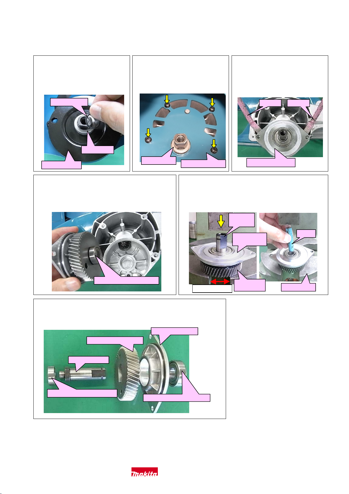
5-3-3 Helical gear 50....................................................................................................................................................6
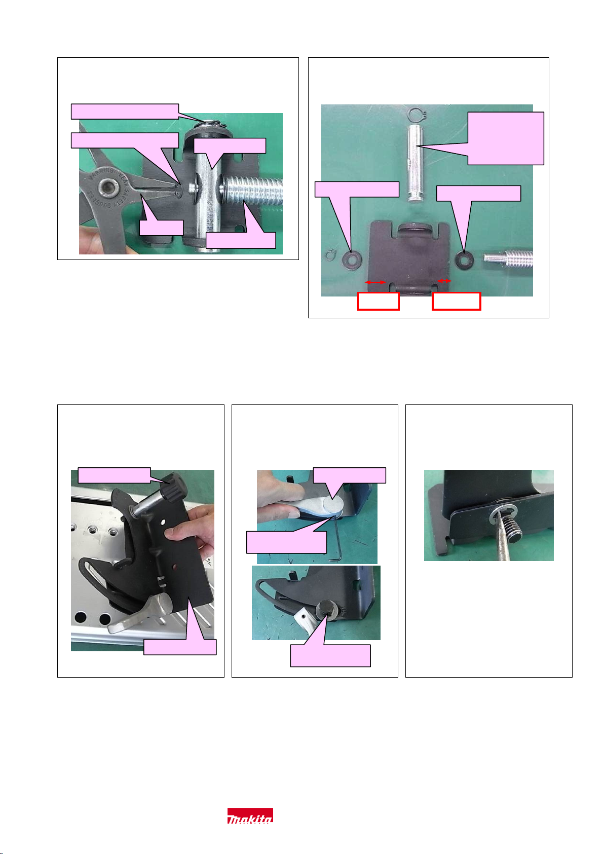
5-3-4 Vise Section ........................................................................................................................................................8
5-3-5 Guide plate..........................................................................................................................................................9
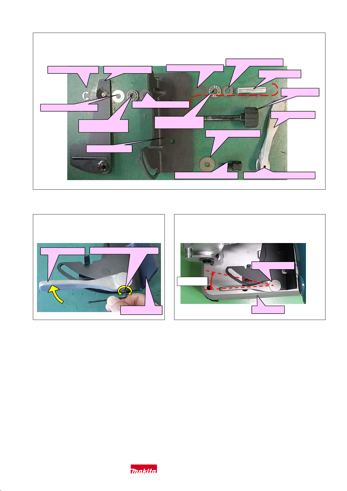
5-3-6 Main frame, Base and others ............................................................................................................................ 11
6Circuit diagram..................................................................................................................................................................13
7Wiring diagram..................................................................................................................................................................14
4Caution
Repair the machine in accordance with “Instruction manual” or “Safety instructions
Follow the instructions described below in advance before repairing:
· Wear gloves.
· Remove Abrasive cut-off wheel.
· When the engine is hot from use, cool down the engine enough or you can get burned.
· In order to avoid wrong reassembly, draw or write down where and how the parts are assembled, and what are the parts.
· It is also recommended to have boxes ready to keep disassembled parts by group.
· Handle the disassembled parts carefully.
· If some bolts and screws are too tight, use an impact driver.
· Tighten the bolts and the screws to the specified torque.
Makita Corporation 2/ 15


 Guide")