PROCEDURE FOR
CHANGING THE BLADE _
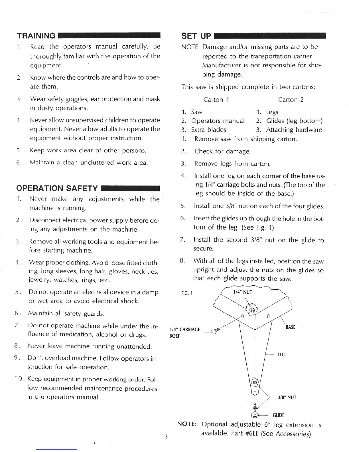
Step 1:
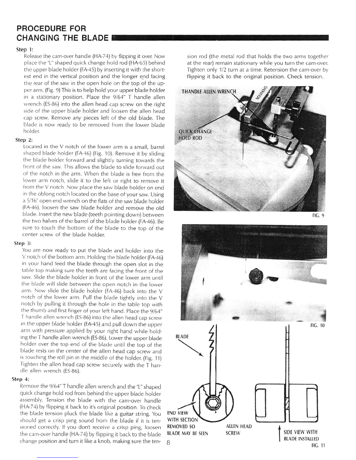
Release the earn-over handle (HA-74) by flipping it over.
I
ow
place the "L" shaped quick change hold rod (HA-65) behind
the upper blade holder (FA-45) by inserting it with the short-
est end in the vertical position and the longer end facing
the rear of the saw in the open hole on the top of the up-
per arm. (Fig.
9)
This is to help hold your upper blade holder
in a stationary position. Place the 9/64" T handle allen
wrench (ES-86) into the allen head cap screw on the right
side of the upper blade holder and loosen the allen head
cap screw. Remove any pieces left of the old blade. The
blade is now ready to be removed from the lower blade
holder.
Step 2:
Located in the
V
notch of the lower arm is a small, barrel
shaped blade holder (FA-46) (Fig. 10). Remove it by sliding
the blade holder forward and slightly turning towards the
front of the saw. This allows the blade to slide forward out
of the notch in the arm. When the blade is free from the
lower arm notch, slide it to the left or right to remove it
from the
V
notch. Now place the saw blade holder on end
in the oblong notch located on the base of your saw. Using
a 5/16" open end wrench on the flats of the saw blade holder
(FA-46), loosen the saw blade holder and remove the old
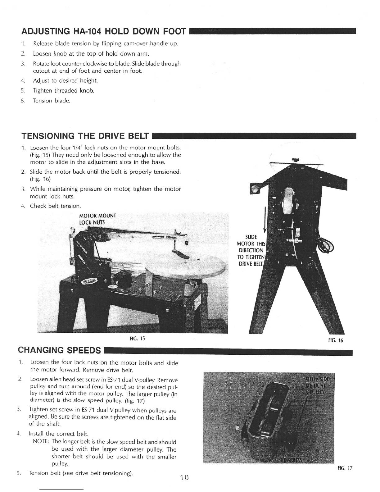
blade. Insert the new blade (teeth pointing down) between
the two halves of the barrel of the blade holder (FA-46). Be
sure to touch the bottom of the blade to the top of the
center screw of the blade holder.
Step
3:
You are now ready to put the blade and holder into the
V notch of the bottom arm. Holding the blade holder (FA-46)
in your hand feed the blade through the open slot in the
table top making sure the teeth are facing the front of the
saw. Slide the blade holder in front of the lower arm until
the blade will slide between the open notch in the lower
arm. Now slide the blade holder (FA-46) back into the V
notch of the lower arm. Pull the blade tightly into the V
notch by pulling it through the hole in the table top with
the thumb and first finger of your left hand. Place the 9/64"
T
handle allen wrench (ES-86) into the allen head cap screw
in the upper blade holder (FA-45) and pull down the upper
arm with pressure applied by your right hand while hold-
ing the T handle allen wrench (ES-86). Lower the upper blade
holder over the top end of the blade until the top of the
blade rests on the center of the allen head cap screw and
is touching the roll pin in the middle of the holder. (Fig. 11)
Tighten the allen head cap screw securely with the T han-
dle allen wrench (ES-86).
Step 4:
Remove the 9/64" T handle allen wrench and the
"L"
shaped
quick change hold rod from behind the upper blade holder
assembly. Tension the blade with the earn-over handle
(HA-74) by flipping it back to it's original position To check
the blade tension pluck the blade like a guitar string. You
should get a crisp ping sound from the blade if it is ten-
sioned correctly. If you don't receive a crisp ping, loosen
the earn-over handle (HA-74) by flipping it back to the blade
change position and turn it like a knob, making sure the ten-
8
sian rod (the metal rod that holds the two arms together
at the rear) remain stationary while you turn the earn-over
Tighten only 1/2 turn at a time. Retension the earn-over by
flipping it back to the original position. Check tension.
FIG.
9
l•. ~
.'
BLADE
<.
FIG.
if-
~
r--
L.-.....o
10
~
END VIEW
WITH SECTION
REMOVED SO
BLADE MAY BE SEEN ALLEN HEAD
SCREW
t
SIDE VIEW WITH
BLADE I STALLED
FIG.11