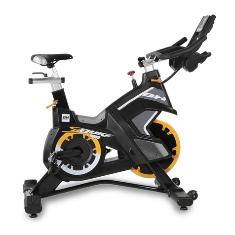
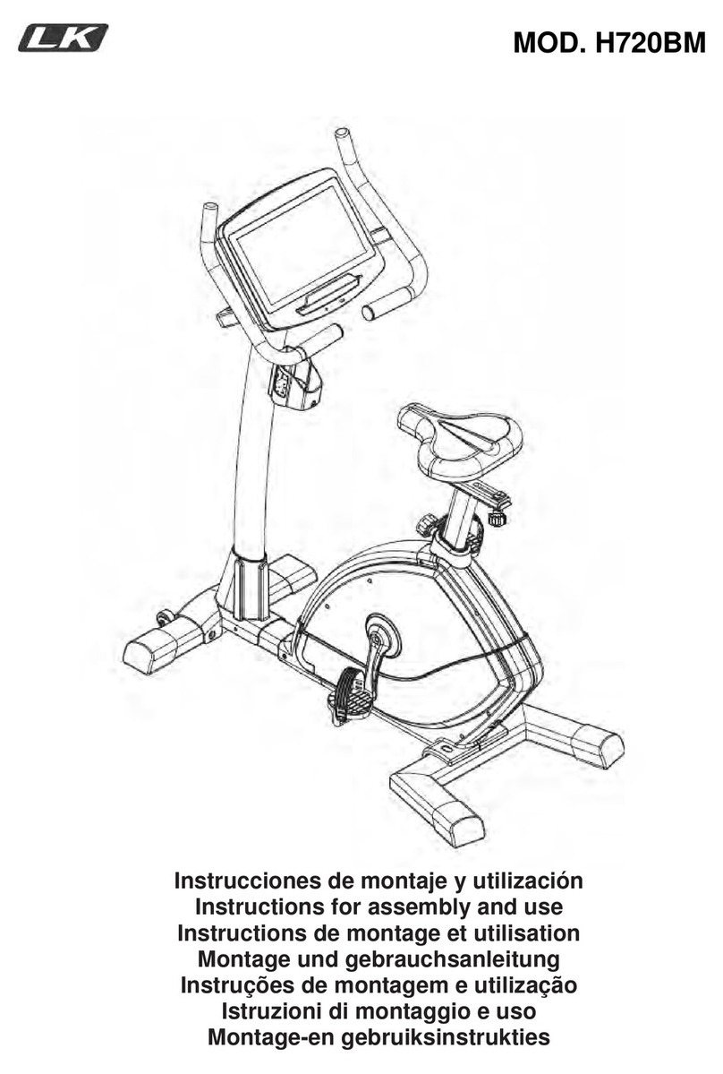
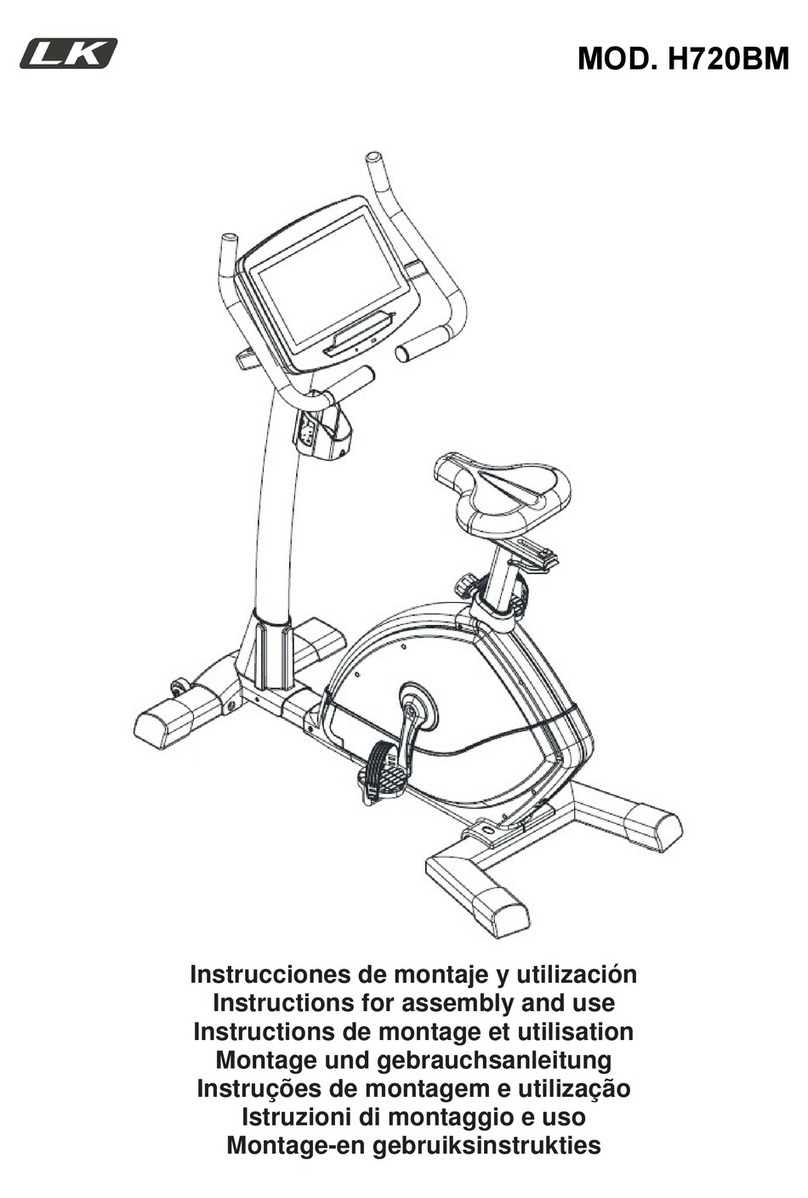
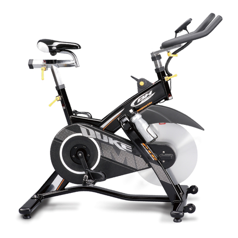
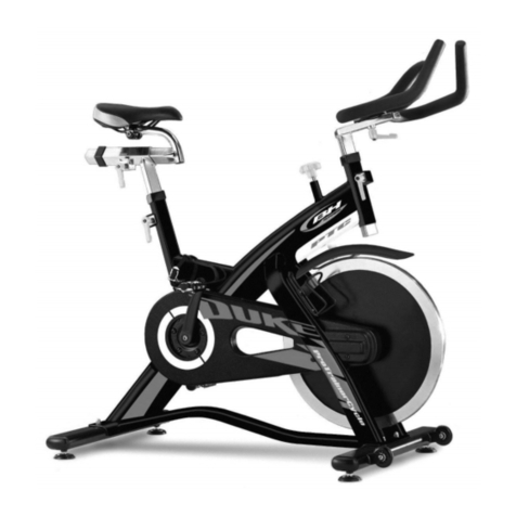
BH Hipower G290 Operator's manual

1
G290
Instrucciones de montaje y utilización
Instructions for assembly and use
Instructions de montage et utilisation
Montage-und Gebrauchsanleitung
Instruções de montagem e utilização
Istruzioni di montaggio e uso
Montage-en gebruiksinstrukties

2
Fig.1
Fig.2 Fig.3

3
Fig.4 Fig.5
Fig.5A
Fig.6 Fig.7

4
Fig.8 Fig.9
Fig.10 Fig.11

5
Español
INSTRUCCIONES DE
SEGURIDAD.-
Antes de comenzar cualquier programa
de ejercicio, consulte a su médico. Se
recomienda la realización de un
examen físico completo.
Trabaje en el nivel de ejercicio
recomendado, no llegue al agotamiento.
Si siente dolor o molestias de cualquier
tipo, pare el ejercicio inmediatamente y
acuda a su médico.
Utilice el aparato sobre una superficie
sólida y nivelada, con algún tipo de
protección para el suelo o alfombra. Por
razones de seguridad, el equipo deberá
disponer a su alrededor de un espacio
libre no inferior a 0,5 m.
No permita a los niños jugar con este
aparato o a su alrededor. Mantenga las
manos alejadas de las partes en
movimiento.
Compruebe la elíptica antes de
comenzar el ejercicio, para asegurarse
de que se han montado todas las
piezas y que las tuercas, tornillos,
pedales y brazos se han apretado
correctamente antes del uso.
Utilice prendas y calzado apropiados
para el ejercicio físico. No utilice
prendas sueltas. No utilice calzado con
suela de cuero o tacones altos.
Este aparato ha sido probado y cumple
con la norma EN957 bajo la clase S.C.
adecuado sólo para uso profesional.
Peso máximo del usuario 115Kg. El
frenado es independiente de la
velocidad.
IMPORTANTE.
Lea las instrucciones detenidamente
antes de proceder con el montaje.
Retire todas las partes del cartón de
embalaje e identifíquelas con respecto
al listado, para asegurarse de que no
falta ninguna.
No elimine el cartón hasta haber
montado la elíptica completamente.
Utilice el aparato siempre de acuerdo
con las instrucciones. Si encuentra
algún componente defectuoso durante
el montaje o comprobación del
aparato, o si oye algún ruido extraño
durante la utilización, pare.
No utilice este aparato hasta que se
haya solucionado el problema.
1) El modelo G290 tiene un volante de
inercia de 20Kg que esta conducido
con rueda fija y se debe utilizar
solamente bajo supervisión
profesional.
2) Es muy importante que el modelo
G290 este montado correctamente y
recomendamos que las personas que
lo monten, estén convenientemente
cualificados para realizar el montaje
de este modelo.
3) Para la realización de los ejercicios
es conveniente que el tubo del
manillar está fijado a la altura correcta
para su cuerpo.
Cerciórese de que esté apretado con
seguridad y observe que no tiene
ningún movimiento lateral o vertical.
Lea atentamente el apartado 9-10, de
regulación y ajuste de altura del tubo
manillar:
4) El G290 tiene que estar asentado
sobre una superficie llana y sin el
movimiento lateral. Hay tacos de
regulación de asentamiento situados
por debajo el tubo trasero (4).

6
Gire estos tacos de regulación a la
derecha o a la izquierda hasta que el
aparato este totalmente estable en el
suelo.
5) El regulador de frenada, actúa
también como freno de seguridad
girando al máximo la palanca de
aumentar la resistencia de frenada.
6) Asegúrese que que tiene un área
libre detrás del aparato y está libre de
cualquier obstáculo.
7) Para un uso regular y fiable del
aparato, lea el programa de
mantenimiento detallado, en las
páginas finales de cada idioma.
INSTRUCCIONES PARA EL
EJERCICIO.-
El uso de la elíptica le reportará
diferentes beneficios, mejorará su
condición física, tono muscular y,
junto con una dieta baja en calorías, le
ayudará a perder peso.
1 La fase de calentamiento.
Esta fase acelera la circulación
sanguínea en el cuerpo y pone a tono
los músculos para el ejercicio.
También reduce el riesgo de
calambres y lesiones musculares. Es
aconsejable realizar algunos ejercicios
de estiramiento, según se muestra
más adelante. Realice cada estira-
miento aproximadamente durante 30
segundos, no fuerce los músculos. Si
siente dolor, PARE.
2. La fase de ejercicio.
En esta fase se realiza el esfuerzo
más importante. Tras el ejercicio
regular, los músculos de las piernas
aumentarán su flexibilidad. Es muy
importante mantener un ritmo
constante. El ritmo de ejercicio será lo
bastante alto para aumentar las
pulsaciones hasta la zona objetivo
que se muestra en el gráfico
siguiente.
Esta fase debería durar un mínimo de
12 minutos aunque se recomienda a
la mayoría de la gente comenzar con
períodos de 10-15 minutos.
3. La fase de relajación
Esta fase permite la relajación del
sistema cardiovascular y muscular. Se
trata de una repetición de los ejercicios
de calentamiento, por ejemplo,
reduciendo el ritmo, y continuando
aproximadamente 5 minutos. Repita
los ejercicios de estiramiento, y
recuerde no forzar los músculos.
Según transcurran los días, necesitará
entrenamiento más prolongados y de
mayor intensidad. Es recomendable
ejercitarse un mínimo de tres días por
semana, en días alternos.
Tonificación muscular.
Para tonificar los músculos durante el
ejercicio deberá seleccionar una
resistencia alta. Esto implicará una
mayor tensión sobre la musculatura
de las piernas y quizás deba reducir el
tiempo del ejercicio.

7
Si también desea mejorar su forma
física general, deberá cambiar su
programa de entrenamiento. Realice
los ejercicios de calentamiento y
relajación de costumbre, pero cuando
esté llegando al final de la fase de
ejercicio, aumente la resistencia para
someter sus piernas a un mayor
esfuerzo. Deberá reducir la velocidad
para mantener el ritmo cardíaco en la
zona objetivo.
Pérdida de peso En este caso, el
factor importante es el esfuerzo
realizado. Cuando más intenso y más
prolongado sea el trabajo, mayor será
la cantidad de calorías quemadas.
Efectivamente, el trabajo es el mismo
que se realiza para mejorar la
condición físico, pero el objetivo es
diferente.
INDICACIONES GENERALES.-
Lea atentamente las instrucciones de
este manual. Este le da indicaciones
importantes sobre el montaje,
seguridad y uso de la máquina.
1 Esta unidad esta diseñada para uso
profesional. El peso de usuario no
debe exceder de 115Kg.
2 Mantenga las manos alejadas de
cualquiera de las partes móviles de la
unidad.
3 Los padres y otras personas
responsables de los niños deben de
tener en cuenta la naturaleza curiosa
de estos y que puede llevarles a
situaciones y conductas que pueden
resultar peligrosas. Esta unidad no ha
de utilizarse en ningún caso como
juguete.
4 Es responsabilidad del propietario
asegurarse que todos los usuarios de
la máquina estén adecuados e
informados sobre todas las
precauciones necesarias.
5 Su unidad sólo puede ser usada por
una persona al mismo tiempo.
6 Utilice prendas de vestir y calzado
adecuado. Átese los cordones
correctamente.
1. INSTRUCCIONES DE
MONTAJE.-
Saque la unidad de la caja y
compruebe que tiene todas las piezas
Fig.1.
Se recomienda la ayuda de una
segunda persona para la
realización de este montaje.
(1) Cuerpo principal.
(2) Tubo manillar.
(3) Tubo caballete delantero con
ruedas.
(4) Tubo caballete trasero con tacos
regulables.
(6) Brazo superior izquierdo.
(7L) Pie izquierdo.
(7R) Pie derecho.
(18)
Tubo tija manillar.
(23) Eje de gir
o brazos.
(26) Brazo superior derecho
(35) Apoya pies izquier
do.
(36) Apoya pies derecho.
(76) Tuerca M-8.
(77) Arandela plana M-8.
(78) Tornillo M-8x50.
Llave de tubo con destornillador estrella
(A) Bote fijador rosca tornillo.
2.- MONTAJE DEL TUBO
MANILLAR.-
Coja el tubo manillar (2) que viene
embalado junto al cuerpo principal (1)
e insértelo en dirección de la flecha,
en el agujero del tubo tija (18) Fig.2,
apriete el pomo (79) en dirección de
las agujas del reloj y coloque el tapon
trasero (20), sujetándolo con los
tornillos (21).

8
A continuación introduzca el tubo de
tija en el saliente del cuerpo principal
(1) como le muestra la Fig.2.
Posiciónelo a una altura media y
apriete el pomo (79) en dirección de
las agujas del reloj Fig.2.
3. COLOCACIÓN DE LOS
TUBOS CABALLETE.-
Coja el tubo caballete trasero (4) con
tacos de regulación Fig.3. Introduzca
los tornillos (78) coloque las arandelas
(77), y las tuercas (76), y apriete
fuertemente.
Acerque el tubo de caballete delantero
con ruedas (3) al cuerpo central (1),
posicionando las ruedas hacia delante
de la unidad, Fig.3, introduzca los
tornillos (78), coloque las arandelas
(77) y las tuercas (76) y ayudándose
de la llave apriete fuertemente.
4. MONTAJE DEL EJE GIRO
BRAZOS.-
Introduzca el eje giro de brazos (23)
por el soporte horizontal del tubo remo
Fig.4 y déjelo centrado, entre las dos
lineas (B) marcadas en el eje. Apriete
fuertemente los tornillos (67).
5. MONTAJE DE LOS PIES.-
Coja el pie derecho (7R), y posicióne
el casquillo del brazo (17) en el eje
(23) Fig.5.
A continuación introduzca la biela (R)
en el cuadradillo del eje (30) Fig.5,
coja el tornillo (27) y apriete
fuertemente la biela.
Coja el tornillo (13) junto con la
arandela (14) y atornille en el eje (23),
Fig.5, apriete fuertemente.
ATENCIÓN: Coja el pie izquierdo
(7L), y realice el mismo montaje que
ha realizado para el montaje del pie
izquierdo (7R), poniendo especial
atencion que el montaje de la biela
izquierda (L) se tiene que quedar a
180 grados con respecto a la biela
derecha (R) como le muestra la
Fig.5A.
Coloque con los tornillos (66) el
portabotellines (34) en el tubo soporte
de tija del cuerpo principal (1) Fig.5A.
AVISO: Es muy importante el
reapretar todos los tornillos que han
intervenido en el montaje de la
máquina, a las primeras horas
aproximadamente de uso de la
maquina, poniendo especial atencion
a los tornillos (27) de las bielas (R ) y
(L) Fig.5A.
6. MONTAJE DE LOS
REPOSAPIÉS.-
Posicione el reposapiés izquierdo (35,
marcado con la letra L) sobre el pie
izquierdo (7L) de la unidad, Fig.5, (la
posición izquierda y derecha en la
unidad es siempre en la posición de
hacer el ejercicio) coja los tornillos
(43), y apriete fuertemente.
Seguido posicione el reposapiés
derecho (36 marcado con la letra R)
sobre el pie derecho (96), coloque los
tornillos (43) y apriete fuertemente.
7. MONTAJE DE LOS
BRAZOS SUPERIORES.-
Coja el brazo superior izquierdo (6)
(marcado con la letra L).
Introduzca el brazo en el saliente del
brazo inferior izquierdo (5L) haciendo
coincidir las letras (L), Fig.6, apriete el
tornillo (T) del brazo inferior 5L con la
llave allen de 8 mm. Seguido realice el
mismo montaje con el brazo superior
derecho (26).
9
8. REGULACIÓN DE
ESFUERZO.-
Para un control de esfuerzo regular de
su ejercicio, este aparato dispone de
un mando de tensión (19), Fig.7.
Para aumentar la resistencia del
pedaleo usted gire el mando de
tensión (19), en sentido de las agujas
del reloj (+), hasta conseguir que el
esfuerzo de su ejercicio es el ideal
para usted. Para disminuir la
resistencia del pedaleo, gire el mando
de tensión (19), en sentido contrario a
las agujas del reloj (-).
9. REGULACIÓN Y AJUSTE DE
ALTURA TUBO MANILLAR.-
1) Afloje en el sentido contrario de las
agujas del reloj, la palanca (79) Fig.8
la que se localiza en el tubo vertical
del cuerpo principal (1) Fig.8.
2) Deslice el tubo del manillar (2)
hacia arriba o hacia abajo a la altura
requerida y vuelva a apretar en el
sentido de las agujas del reloj la
palanca de (79) Fig.8.
10. REGULACIÓN Y AJUSTE
HORIZONTAL DEL TUBO
MANILLAR.-
1) Afloje en el sentido contrario de las
agujas del reloj, la palanca (79) Fig.9
la que se localiza en el tubo vertical
del cuerpo principal (1) Fig.9.
2) Deslice el tubo del manillar (2)
hacia delante o hacia atrás a la
medida requerida y vuelva a apretar
en el sentido de las agujas del reloj la
palanca de (79) Fig.9.
ATENCIÓN:
Es muy importante el reapretar todos
los tornillos que han intervenido en el
montaje de la maquina, a la semana
aproximadamente de uso de la
maquina, con ello evitaremos ruidos
raros y posibles averías.
NIVELACIÓN.-
Una vez colocada la unidad en su
lugar definitivo, para la realización del
ejercicio, compruebe que el
asentamiento en el suelo y su
nivelación sean correctos. Esto se
conseguirá roscando mas o menos los
pies regulables (87) como muestra la
Fig.10.
MOVIMIENTO Y
ALMACENADO.-
La unidad está equipada con ruedas
(59) lo que hace más sencillo su
movimiento. Las ruedas que se
encuentran en la parte delantera de
su unidad, le facilitarán la maniobra de
colocar su unidad en el
emplazamiento escogido, levantando,
ligeramente por la parte delantera y
empujando, como muestra la Fig.11.
Guarde su máquina en un lugar seco
con las menores variaciones de
temperatura posible.
BH SE RESERVA EL DERECHO A
MODIFICAR LAS
ESPECIFICACIONES DE SUS
PRODUCTOS SIN PREVIO AVISO.
Para cualquier consulta, no dude en
ponerse en contacto, llamando al
número de atención al cliente.
+34 902 170 258

10
G290
CUADRO DE MANTENIMIENTO
Nº
DESCRIPCIÓN Diario Semanal Mensual
Trimestral Anual
1 Limpiar la máquina.
X
2 Limpiar y secar la estructura
principal y carcasas con
detergentes neutros.
X
3 Realizar una inspección visual
de las partes móviles.
X
4 Comprobar la sujecion del tubo
del manillar.
X
5 Comprobar la sujecion de los
brazos oscilantes superiores e
inferiores.
X
6 Comprobar la seguridad de la
frenada de emergencia.
X
7 Comprobar el desgaste y
alineación de las zapatas de
freno
X
8 Comprobar el sistema de
resistencia de frenada.
X
9 Comprobar los tornillos de las
bielas y reapretar
X
10 Asegurarse de que el eje de los
brazos está apretado.
X
11
Comprobar la tensión de la
cadena.
X
12 Lubricar la cadena.
X
13 Aplicar aceite anticorrosión en
los laterales del volante de
inercia.
X
14 Comprobar el apriete de los
soportes caballete.
X
15 Comprobar que los rodamientos
del volante de inercia no hagan
ruido.
X
16 Realizar la inspección de
mantenimiento del panel
principal.
X

11
11).-Metodo de ajuste para la tensión de la cadena –
La cadena de transmisión es normal que pierda tensión, según la frecuencia de
utilización y con el tiempo.
Procedimiento de tensado.- Fig.A
1)
Aflojar la tuerca de seguridad del volante de
inercia (69) Fig.A.
2)
Girando las tuercas de ajuste (22) en el
sentido contrario a las agujas del reloj
(Visto por la figura) y en lado opuesto en el
sentido de las agujas del reloj, ajustar la
tensión de la cadena.
3)
Se aconseja girar ¼ de vuelta cada vez en
los dos lados del volante de inercia.
4)
No girar las tuercas de ajuste en exceso,
porque la tensión de la cadena podría ser excesiva y dañarse el eje
repercutiendo también en los rodamientos del volante de inercia.
5)
Tras finalizar los pasos anteriores, apriete fuertemente las tuercas de
seguridad (69) en ambos lados del volante de inercia.

12
English
SAFETY INSTRUCTIONS.-
Consult your doctor before starting
any exercise program. It is advisable
to undergo a complete physical
examination.
Work at the recommended exercise
level, do not overexert yourself. If you
feel any pain or discomfort, stop
exercising immediately and consult
your doctor.
Use the appliance on a solid, fl at
surface, with some type of protection
for the floor or carpet. In the interest of
safety, the equipment must have at
least 0.5 metres of free space around
it.
Do not allow children to play with the
equipment or in the immediate vicinity.
Keep your hands well away from any
of the moving parts.
Check the elliptical trainer before
starting the exercise; to make sure
that all of the parts are attached and
that the nuts, bolts, pedals and focus
bars have been tightened correctly
prior to use.
Wear appropriate clothing and
footwear for the exercise. Do not use
loose clothing. Do not wear leather
soled shoes or footwear with high
heels.
This appliance has been tested and it
complies with standard EN957 under
class S.C., suitable for professional
use only. Maximum user weight
115Kg. Braking is independent of
speed.
IMPORTANT:
Read the instructions carefully before
proceeding to assemble the
equipment.
Remove all the parts from the
cardboard packaging and check them
against the parts list to ensure that
there is nothing missing.
Do not throw the cardboard away until
the elliptical trainer is fully assembled.
Always use the appliance in
accordance with the instructions. If
you discover any defective component
while assembling or checking the
equipment, or if you hear any strange
noise during exercise then stop. Do
not use the appliance until the
problem has been resolved.
1) The G290 model has a 20kg fixed
inertia flywheel and must only be used
under professional supervision.
2) It is very important that the G290
model is assembled correctly, so we
recommend that the people who
assemble it are suitably qualified to do
so.
3) When exercising it is advisable to
set the handlebar stem to the correct
height for your body.
Make sure that it is tightened securely
and that there is no side or vertical
movement. Carefully read section 9-
10 on how to adjust the height of the
handlebar stem.
4) The G290 has to rest level on a flat
surface with no wobbling. There are
adjustable feet located below the rear
stand (4).
Turn to feet to the left or right so that
the unit is completely stable on the
floor.
5) The brake controller also acts as a
safety brake by turning the exertion
level lever to the maximum position.

13
6) Make sure that there is adequate
free space behind the unit, free of
obstacles.
7) To ensure regular trouble-free use,
read the detailed maintenance
program on the last pages for each
language.
EXERCISE INSTRUCTIONS.-
Use of the ELLIPTICAL TRAINER
offers various benefits; it will improve
fitness, muscle tone and when used in
conjunction with a calorie controlled
diet it will help you to lose weight.
1,Warm-up phase.
This phase speeds up the body’s
blood circulation and gets the muscles
ready for exercise. It also reduces the
risk of cramp and sprains. It is
advisable to do some stretching
exercises, as shown below. Each
stretch should last approximately 30
seconds, do not overexert the
muscles. If you feel pain, STOP.
2. Exercise phase.
This phase requires the greatest
physical exertion. After regular
exercise the leg muscles will become
more flexible. It is important to keep
the rhythm constant. The rhythm of
the exercise should be fast enough to
bring the heart rate into the target
area, as shown on the following graph:
This phase should last at least 12
minutes, although it is advisable for
most people to start off with sessions
of 10-15 minutes.
3. Cool-down phase.
This phase allows the cardiovascular
and muscle system to relax. It consists
of repeating the warm-up exercises,
i.e. reducing the rhythm and
continuing for approximately 5
minutes. Repeat the stretching
exercises but remember not to
overexert the muscles.
Eventually your training sessions will
have to become longer and more
intensive. It is advisable to exercise at
least three days per week, on
alternate days.
Muscle toning.
You should select a high exertion level
in order to tone muscles during
exercise. This entails greater stress on
the leg muscles, so it may be wise to
reduce exercise times. If you also wish
to improve your overall fitness then
you should change your training
program. Do the warm-up and cool
down exercises as normal but when
you are reaching the end of the
exercise phase, increase the exertion
level in order to make your legs work
harder. You should reduce speed in
order to keep your heart rate within
the target area.

14
Weight loss.
In this case the important factor is the
effort made. The more intense and the
longer the session, the greater the
number of calories burned. Even
though you are dong the same work
as you do to improve fitness, the
objective has changed.
GENERAL INSTRUCTIONS.-
Carefully read through the instructions
contained in this manual. It provides
you with important information about
assembly, safety and use of the
machine.
1 This unit has been designed for
professional use. The weight of the
user must not exceed 115kg.
2 Keep your hands well away from
any of the moving parts.
3 Parents and/or those responsible for
children should always take their
curious nature into account and how
this can often lead to hazardous
situations and behaviour resulting in
accidents. This unit does not have to
be used in any case like toy.
4 The owner is responsible for
ensuring that anyone who uses the
machine is duly informed about the
necessary precautions.
5 Your unit can only be used by one
person at a time.
6 Use suitable clothing and footwear.
Tie up your shoelace correctly.
1. ASSEMBLY INSTRUCTIONS.-
The assistance of a second person
is recommended when assembling
this unit.
Take the unit out of its box and make
sure that all of the pieces are there
Fig.1:
(1) Main body.
(2) Handlebar tube.
(3) Front stabiliser bar with wheels.
(4) Rear stabiliser bar with
adjustable feet.
(6) Top focus bar, left.
(7L) Left footrest.
(7R) Right footrest.
(18) Handlebar post.
(23) Focus bar spindle
(26) Top focus bar, right.
(35) Left footrest
(36) Right footrest
(76) Self-locking nuts M-8.
(77) Flat washer M-8.
(78) Screw M-8x50.
Box spanner with star screwdriver.
(A) Bottle of threadlocker.
2.- ATTACHING THE
HANDLEBAR STEM.-
Take the handlebar stem (2)
packaged in with the main body (1)
and insert it into the handlebar post
(18) in the direction of the arrow,
Fig.2. Tighten knob (79) by turning it
clockwise and fit the end cover (20),
securing it by using screws (21).
Next, insert the handlebar post into
the boss on the main body (1) as
shown in Fig.2.
Position it for average height and
tighten by turning the retaining knob
(79) clockwise, Fig.2.
3. FITTING THE STABILISER
BARS.-
Take the rear stabiliser bar with
adjustable feet (4), Fig.3, insert the
bolts (78); fit the washers (77) and the
nuts (76) and tighten securely.
Bring the front stabiliser bar with
wheels (3) to the main body (1)
positioning the wheels at the front of
the unit, Fig.3, insert screws (78), fit the
corrugated washers (77) and the nuts
(76). Use the key to tighten securely.

15
4. FITTING THE FOCUS BAR
SPINDLE.-
Insert the focus bar spindle (23)
through the horizontal support on the
main post, Fig.4, leaving it centred
between the two lines (B) marked on
the spindle. Tighten screws (67)
securely.
5. FITTING THE FEET.-
Take the right foot (7R) and fit the
bush for the focus bar (17) onto the
spindle (23) Fig.5.
Next, insert the connecting rod (R)
onto the square shaft (30), Fig.5, and
use screw (27) to tighten the
connecting rod securely.
Take screw (13), along with washer
(14) and tighten it securely onto the
spindle (23), Fig.5.
ATTENTION: Take the left foot (7L)
and perform the same assembly
procedure as with the right foot (7R),
making sure that the left connecting
rod (L) is at 180 degrees with respect
to the right connecting rod, as shown
in Fig.5A.
Fit the bottle holder (34) onto the
handlebar post support on the main
body (1) using screws (66), Fig.5A.
WARNING:
It is important to retighten all of the
screws involved in assembling the
machine after a few hours of use,
paying special attention to screws (27)
for the connecting rods (R) and (L),
Fig.5A.
6. FITTING THE FOOTRESTS.-
Position the left footrest (35 marked
with the letter “L”) on top of the unit’s
left foot (7L), Fig.5, (left and right
refers to the user’s position doing
exercise) refit the screws (43), and
tighten securely.
Next, position the right footrest (36
marked with the letter “R”) on top of
the right foot (7R), refit the screws
(43), and tighten securely.
7. FITTING THE UPPER
FOCUS BARS.-
Take the top left focus bar (6) (marked
with the letter L).
Insert the bar into the bottom left focus
bar (5L), lining up the letters (L), Fig.6,
tighten screw (T) on the bottom focus
bar (5L) with the 8 mm Allen key. Now
go through the same procedure for the
top right focus bar (26).
8. EXERTION SETTINGS.-
To provide an even level of exertion
during exercise, this appliance is
equipped with a tensioning control
(19), Fig.7.
To increase pedal resistance turn the
tensioning control (19) clockwise (+)
until the exertion level best suits your
exercise requirements. To reduce
pedal resistance turn the tensioning
control (19) anticlockwise (-).
9. HANDLEBAR STEM
HEIGHT ADJUSTMENT.-
1) Loosen lever (79), located on the
vertical tube on the main body (1),
Fig.8, by turning it anticlockwise.
2) Slide the handlebar stem (2) up or
down to the required height and then
retighten the lever (79) by turning it
clockwise, Fig.8.

16
10. ADJUSTING THE
HANDLEBAR TUBE
HORIZONTALLY.-
1) Loosen lever (79), located on the
vertical tube on the main body (1),
Fig.9, by turning it anticlockwise.
2) Slide the handlebar stem (2)
backwards or forwards to the required
position and then retighten the lever
(79) by turning it clockwise, Fig.9.
ATTENTION:
It is important to retighten all of the
screws involved in assembling the
machine after approximately a week of
use as this will prevent any strange
noises and possible damage.
LEVELLING.-
Once the unit has been placed into its
fi nal position, make sure that it sits fl
at on the floor and that it is level. This
can be achieved by screwing the
adjustable feet (87) up or down, as
shown in Fig.10.
MOVEMENT & STORAGE.-
The unit is equipped with wheels (59)
to make it easier to move. The wheels
located at the front of your unit make it
easier to move it into a chosen
position, by lifting the rear of the unit
up slightly and pushing it, as shown in
Fig.11. Store your unit in a dry place,
preferably not subject to changes in
temperature.
BH RESERVES THE RIGHT TO
MODIFY THE SPECIFICATIONS OF
ITS PRODUCTS WITHOUT PRIOR
NOTICE
Do not hesitate to get touch with us if
you have any queries, by calling:
+44 0844 335 3988
service@bh-uk.co.uk

17
G290
MAINTENANCE TABLE
Nº
DESCRIPTION
Daily
Weekly
Monthly
3 monthly
Yearly
1 Clean the machine
X
2 Clean and dry the main body
and casing using neutral
detergents
X
3 Visually inspect the moving
parts
X
4 Check that the handlebar stem
is secure
X
5 Check that the top and bottom
focus bars are secure
X
6 Check that the emergency
braking operates correctly.
X
7 Check the wear and alignment
of brake shoes.
X
8 Check the braking system
X
9 Check the screws on the
connecting rods and retighten
X
10 Make sure that the focus bar
spindle is tight
X
11
Check the chain tension.
X
12 Lubricate the chain
X
13 Apply anti-corrosive oil to the
sides of the flywheel.
X
14 Check that the stabiliser
supports are tight.
X
15 Check for noisy bearings on the
inertia flywheel
X
16 Perform maintenance inspection
of the main panel.
X

18
11).- Tensioning the chain -
It is normal for the drive chain to become slack with use and over time.
Tensioning procedure.- Fig.A
1)
Loosen the safety bolt on the inertia
flywheel (69) Fig. A.
2)
Adjust the chain tension by turning the
adjustment nuts (22) anticlockwise (on the
side shown in the diagram) and clockwise
on the other side.
3)
It is advisable to make a ¼ turn each time
on both sides of the flywheel.
4)
Do not turn the adjustment nuts
excessively, otherwise the chain will be
overtightened and may damage the shaft as well as the bearings on the
flywheel.
5)
After completing the steps above, retighten the safety nuts (69) on both sides
of the flywheel.

19
Français
CONSIGNES DE SÉCURITÉ.-
Avant de commencer tout exercice,
demandez l’avis de votre médecin. Il
est conseillé de passer un examen
médical complet.
Travaillez le niveau d’exercice
recommandé, ne pas aller jusqu’à
l’épuisement. En cas de douleur ou de
malaise, arrêtez immédiatement
l’exercice et consultez votre médecin.
Cet appareil doit être posé sur une
surface solide et bien nivelée avec
une protection ou un tapis au sol. Pour
mesure de sécurité, prévoir autour de
la machine un dégagement d’au
moins 0.50 mètres.
Il est interdit aux enfants de jouer avec
cet appareil ni aux abords de celuici.
Les mains doivent être tenues à l’écart
des parties amovibles de l’appareil.
Avant de commencer l’exercice, vérifiez
si toutes les pièces ont bien été
montées sur la machine et si les écrous,
vis, pédales et bras sont bien fixés.
L’utilisateur de la machine doit porter
des vêtements et des chaussures
appropriés pour l’exercice physique.
Ne pas porter de vêtements amples,
ni des chaussures à semelle en cuir ni
à talons hauts.
Cet appareil a été testé et répond à la
norme EN957 classe S.C. apte pour
l’usage professionnel uniquement.
Poids maximum de l’utilisateur:
115Kg. Le freinage est indépendant
de la vitesse.
REMARQUES IMPORTANTES.-
Avant de monter la machine, lire
attentivement cette notice.
Sortiez toutes les pièces de
l’emballage en carton et vérifiez sur la
liste qu’il ne manque aucun élément.
Ne pas jeter l’emballage avant d’avoir
monté complètement la machine.
L’appareil doit toujours être utilisé
selon les instructions. Si au cours du
montage ou de la vérifi cation de
l’appareil, vous constatez qu’un
élément est défectueux ou si vous
entendez un bruit étrange
durantl’utilisation, ne pas utiliser la
machine avant d’avoir résout le
problème.
1) Le modèle G290 dispose d’un
volant d’inertie de 20kg conduit avec
une roue fixe et qui doit être utilisé
uniquement sous la surveillance d’un
professionnel.
2) Il est très important que le modèle
G290 soit correctement monté par des
professionnels qualifiés pour ce faire.
3) Pour réaliser les exercices le tube
guidon doit être fixé à la hauteur
requise pour votre taille.
Vérifiez que cet élément est
parfaitement fixé et qu’il ne se déplace
pas latéralement ni verticalement. Lire
attentivement le paragraphe 9-10
concernant le réglage et l’ajustement
de la hauteur du tube du guidon.
4) Le G290 doit être fixé sur une
surface plane et ne doit pas se
déplacer latéralement. Des chevilles
de réglage de la fixation sont placées
sous le tube arrière (4).
Tournez ces chevilles de réglage vers
la droite ou vers la gauche jusqu’à ce
que l’appareil soit complètement
stable au sol.
5) Le système de régulation du
freinage s’utilise également comme
frein de sécurité en tournant à fond le
levier d’augmentation de la résistance
de freinage.

20
6) Il faut prévoir un dégagement
derrière l’appareil et retirer tout
obstacle éventuel.
7) Pour une utilisation régulière et
fiable de l’appareil, veuillez lire le
programme de maintenance figurant
dans les dernières pages de cette
notice.
INSTRUCTIONS POUR
L’EXERCICE.-
L’utilisation de la BICYCLETTE
ELLIPTIQUE vous apportera de
nombreux avantages, améliorera votre
forme physique, votre tonus
musculaire et conjointement à une
alimentation basse en calories, vous
permettra même de perdre du poids.
1. Phase d’échauffement.
Cette phase accélère la circulation
sanguine et prépare les muscles pour
l’exercice. Elle réduit également les
risques de crampes et de lésions
musculaires. Il est conseillé de faire
quelques exercices d’étirement
comme indiqué ciaprès.
Chaque étirement doit durer environ
30 Secondes. Ne pas forcer les
muscles. En cas de douleur,
ARRÊTEZ l’exercice.
2. Phase de l’exercice.
Il s’agit de la phase dans laquelle est
réalisé l’exercice le plus important.
Après l’exercice réalisé régulièrement,
les muscles des jambes deviennent
plus fl exibles. Il est très important de
maintenir un rythme constant. Le
rythme de l’exercice sera
suffisamment élevé pour augmenter
les pulsations jusqu’à la zone-objectif
indiquée sur le schéma suivant.
Cette phase devrait durer 12 minutes
au moins quoi qu’il soit plutôt
recommandé à la plupart des
personnes de commencer par des
exercices de 10 à 15 minutes.
3. Phase de relaxation.
Cette phase permet le relâchement du
système cardio-vasculaire et
musculaire. Il s’agit d’une répétitiondes
exercices d’échauffement. Exemple:
réduire le rythme et en continuant
environ 5 minutes, répétez les exercices
d’étirement et n’oubliez surtout pas de
ne pas forcer les muscles.
Après plusieurs jours d’entraînement,
les séances devront être plus longues
et plus intenses. Il est recommandé de
s’entraîner au moins trois jours par
semaine et d’alterner ces journées
d’entraînement durant la semaine.
Tonification musculaire.
Pour tonifier les muscles durant
l’exercice, il faudra sélectionner une
résistance élevée. Cela se traduira par
une tension plus élevée également sur
la musculature des jambes et il faudra
peut être aussi réduire la durée de
l’exercice. Si vous souhaitez améliorer
votre forme physique en général, vous
devrez modifier votre programme
d’entraînement.
Table of contents
Languages:
Other BH Hipower Exercise Bike manuals

BH Hipower
BH Hipower H946 Operator's manual

BH Hipower
BH Hipower Duke H925 Operator's manual

BH Hipower
BH Hipower LK H720BM Operator's manual

BH Hipower
BH Hipower H925ANT Operator's manual

BH Hipower
BH Hipower G795 Quick setup guide

BH Hipower
BH Hipower H720BM Operator's manual

BH Hipower
BH Hipower SK LINE H800Tv Operator's manual

BH Hipower
BH Hipower H940 Operator's manual

BH Hipower
BH Hipower H923 Operator's manual

BH Hipower
BH Hipower SK LINE H800Tv User manual