BIC 940 User manual

@OO Muftiple Ptay Manuat rurntabtes
3
c
Bert Drive O Moder r-rlffi'i; Xl3ll
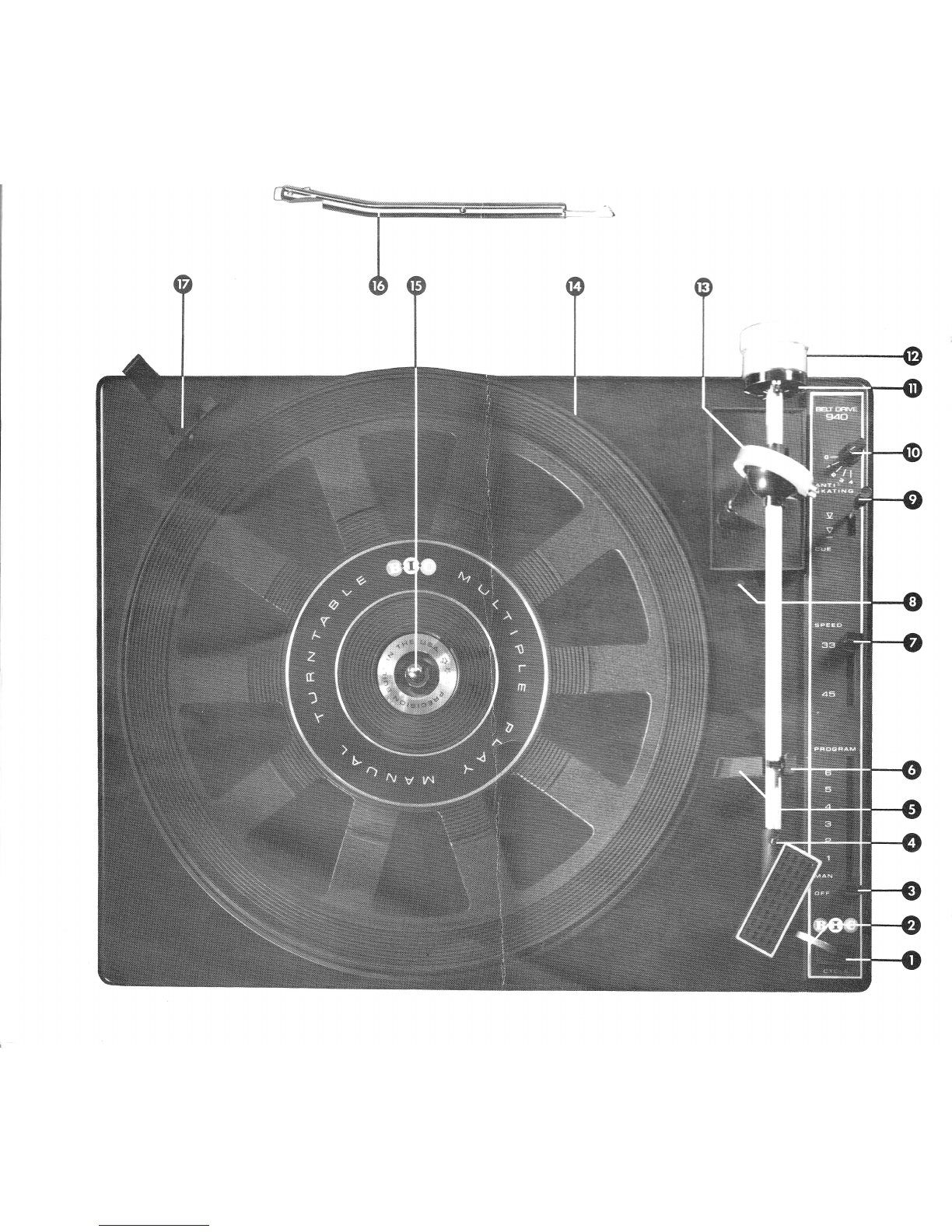

Features of B'l'C Model 940 Multiple Play Manual Turntable
1 Cycie button-feather touch
conirol activates all turntable
:lurrCtiOns
2" Tcnearm f inger lift-human-
engineered f or positive, secure
rnanual handling of tonearm.
3. Program-selects manual or
automatic operation, shut-off
and number of plays.
4 Cartridge shell retaining screw-
locks shellfirmly in place.
5, Tonearm rest-extended for
stylus and cartridge protection.
6. Tonearm lock-prevents damage
during transport or accidental
jarring.
7. Speed selector-shifts drive belt
f or 331/z rpm or 45 rpm rotation.
B. Tonearm set-down adjustment-
adjusts set-down position of stylus
at edge of record.
9. Cueing lever-initiates safe,
damped lowering or raising of
tonearm or can be used as
pause co ntrol.
1 0. Anti-skate f orce ad justment knob
-sets correspond ing a nti-skate
f o rce.
11. Tracking force indicatol-sslg
desired tracking force f rom 0 to
4 grams.
12. lsolated tonearm counterweight
permits dynamic zero balancing ot
entire tonearm, while insuring
maximum damping
13 Precision gimbal bearings-for
minimal ho rizontal and vertical
pivotal f rictio n.
14. 12" diecast platter-solid, one-
piece precision casting has
computer optirnized mass.
15. Removable manual spindle,
1 6. Automatic spind le-su pports
records duri ng automatic
record play
17 . Record support-platform
stabilizes records placed on
spindle for safe two-point
support during automatic play.
18. Elastomer suspension mounts
-correlated to the mass of the
turntable assembly for maximum
isolation from external shock
in all planes.
19. Synchronous 24 pole motor-oper-
ates at slow, vibration-free 300 rpm.
(18 and 19 pertain to underside of unit not shown)
The B.l.C Multiple Piay Manual Turntable
represents the culmination of many years
of engineering design effort directed
towards the development of a superior
rnanual turntable equipped with auto-
matic, multiple record playing facilities.
Its drive system utilizes a slow speed
(300 rpm) 24 pole synchronous motor,
and belt drive, previously found only in
fine manual turntables.This results in
significantly reduced rumble, wow, and
flutter since idler-pulleys are totally
eliminated The Model 940 maintains
precise speed over a wide ran ge of power
line voltages, since its motor's rotational
rate is determined solely by power line
f requency (50 Hz or 60 Hz).
The tonearm system features minimal
friction bearings, low mass and
resonance, stylus force, and tonearm
balancing and an isolated counterweight
to maintain optimal tracking force from
the first to last record played. Another
exclusive feature, a pivotable cartridge
shell, permits easy cartridge installation.
The programmer system eliminates the
i n herent shortcomings of conventional
turntables because its action is inde-
pendent of erratic spindle-sensing
mechanisms or di mensional variations
of records. The programmer allows for
totally manual play or automatic play of
single records, repeat playing of single
records, programmed pl?y of up to six
records, or automatic play of multiple
records with programmed repeatability of
the last record, all by means of a single
touch button.
The suspension system has been
designed to prevent mechanical or
acoustic vi bration coupli ng, thereby
permitting you to take f ull advantage of
the wide dynamic musical range now
available in modern disc recordings.
lndex
Set-Up How to properly unpack the unit
Procedures Note the accessories supplied
lnstalling the turntable on the base
Proper mounting of the cartridge in the tonea'n'^ s^eil
lnstalling the counterwei ght
Adjusting proper tracking and anti-skate fcrces
lnstallation of audio cable and ground ccn"ec:to'r
Connecting to AC power
Operating Man ual play of a single record
Procedures
There are many playing and
operating options built into
your B.l.C Multiple Play
Manual Turntable, plus a
number of unique control
features. These are sum-
mari zed on th is page - and
specific operati n g instruc-
tions for the various playing
options are detailed on the
pages indicated. Normal
mai ntenance proced ures
are also described and
listed, along with a set of
specifications which will be
of interest to the audio
enth us iast.
Programmed repeat play of a single recoi'C
Automatic play of a single record
Autonnatic play of multiple records
Multiple play of records plus repeat of last recorC
Use of cueing and pause control
Adjustnnent of stylus set-down point and tonearrr height
Tips on record care
Spare parts list
G en eral specifications
PAGE
10
10
10
11
11
Turntable removal 12
Drive belt installation 12
Lu brication i nstructions 13
13
13
Accessories 13
14
11
Trou ble-shootin g hints 15

Set-LJp Procedures
'(ffi
Wrffi
Unpacking the Unit
Remove the unit from the bottom styrofoam filler by grasping the
unit plate at the points indicated on the top cardboard packing
piece. DO NOT lift the unit by grasping the tonearm. Whenever
possible, the packing material should be retained in the event re-
shipment is necessary. ln any event, do not discard the packing
material until all of the accessories described below are accounted
fo r.
The top styrofoam filler contains the following:
1 A short manual spindle for playing single records
2, A long automatic spindle for playing up to six records automatic-
ally.
3. Tonearm counterbalance weight,
4. A manual 45 rpm adaptor for playing large hole records, one at a
time.
5. Cartridge mounting hardware; this contains the various screws
that are needed for mounting the cartridge in the pickup head.
6, Transit wing nuts (2)
7 . Extra tonearm shell lock screw.
B. Screwdriver
Also, make certain that all rubber bands securing the line cord,
audio cables, the tonearm tie, etc,, are removed along with all other
packing pieces.
Packing pieces are installed between the unit plate and turntable.
They must also be removed and, if possible, should be retained as
they are avery important part of the packing if the unit is ever
shipped
The audio cable is packed in a wedge on the right side of the unit.
lnstalling the Unit on the Base
Both the 820 Base and WB20 Base are supplied with a bottom
safety cover which eliminates any possibility of mechanical hazard.
Comprehensive instructions are included with each base.
PROPER INSTALLATION IS EXTREMELY IMPORTANT DO NOT
INSTALL THIS UNIT ON ANY DEVICE OTHER THAN THE OFFICIAL
B2O OR WB2O BASES

Cartridge Installation and Adiustment
ln order to take advantage of the many
features of the B.l.C tonearm, it is ex-
tremely important that the cartridge be
properly installed and th e various
adjustments pertaining to the cartridge
be made. These are described below.
Rotation of the Cartridge Head
All turntables use some form of cartridge
slide or clip to pre-mount the cartridge
and fasten it to the arm. Electrical contact
for transmission of the minute cartridge
signals depends on four surface-to-
surface contacts, any one of which may
cause intermittent signals or open
circurts. The B.l.C 940 employs a rotating
pickup head which is rigidly iocked in
place by a set screw lccated on the top
of the tonearm, (Fig A) Rer.nove the set
screw and rotate the pickup head counter
clockwise BE SURE NOT TO LOSE CR
MISPLACE THE SET SCREW IN THE
EVENT THIS OCCURS, AN EXTRA
SCREW HAS BEEN SUPPLIED THE
CARTRIDGE HEAD IS NOT REMOVABLE
AND DAMAGE CAN OCCUR IF IT IS
PULLED FORWARD
Mounting Cartridge in Head
The B.l.C 940 is supplied with several
sets of varied length cartridge rnounting
screws. lt is important that the rnounting
screws used are the correct len gth
ln most cases the mounting screws
supplied by the cartridge manufacturer
should be used. However, if you do not
have these screws, proceed as follows:
From the sets of screws supplied with
the B.l.C 940, select the screws that
appear to be the proper length to pass
through the cartridge mounting bracket
Place one screw through the bracket, To
make certain it is not too long, place the
bottonn of the cartridge as shown in the
diagrarn below and note whether the
screw projects below the simulated
pickup head rnounting bracket lf too
long, use the next shorter screw, When
the correct length has been selected, use
a srnall screwdriver to secure both
screws to the pickup head (Fig B)
Pl ace
Cartridge
Botto m
Here
Th ic k ness
Fig. B
Wiring Cartridge
The chart (Fig C) illustrates the
markings at the rear of a typical cartridge.
MAKE CERTAIN that the cartridge is
wired as per the following diagrams,
I
@-o O
o-@ - Left Grd
Irrir re - Right Grd.
,', '3 _ Left Hot
'. - Right Hot
Fig. C
CAUTION-Never solder directly to the cartridge.
DAMAGE WILL OCCUR.
IMPORTANT WARNING
Tc i:rSUi'e r'ra;<lrr.un iraC<irg capabiIity,
t^e :oi'earm,','' ng ia'ness containing
t^e ca'-.'clg cl-^ec:c's rs nrade of
speciai i.git arge lc',,/ friction wire.
Alt^o-g. t'e cortnections are carefully
mace. special care nnust be taken to
avc;C oreakrr g tre press-on cartridge
ccnnectcis \,viile installing the cartridge
ln stallin g
Grasp the ccn nector in th e cenler with a
pair of tr,veezers or needle nosed pliers.
Caref ully press the connector on to the
pin of the cartridge lf you have difficulty
sliding it on all the way, place a small
screwd river at the point shown in the
diagrarn and gently push the connector
in place

Do not attempt to install the connector
with your fingers, Tweezers or long nosed
pliers must be used. The wire or where
the wire joins to the connector must not
be touched.
Removing
Place a screwdriver between the car-
tridge connector and the rear of the
cartrldge. S/ide the press-on connector
off the cartridge pin Do not use tweezers
or long nosed pliers to remove the
cartridge connector. lf you attempt this,
the removal tool may slip from the
connector and f racture one of the wires.
WE STRESS THAT IF THE INSTRUC_
TIONS ARE NOT CAREFULLY
FOLLOWED AND THE CARTRIDGE
CONNECTORS ARE BROKEN, THE
REPAIR OF THE UNIT WILL NOT BE
COVERED UNDER WARRANTY
Gartridge G rounding Strap
The tonearm ground of the 940 is carried
up to the metal plate in the tonearm head.
With some cartridges a ground loop can
occur-if this difficulty is encountered,
remove the grounding strap f rom the
cartridge. Consult the cartridgd
manufacturers instructions regarding
removal of the ground strap.
Re-positioning Pickup Head
After the cartridge has been correctly
installed in the head, rotate the shell
clockwise so that the hole which receives
the screw becomes visible. Replace
the set screw and tighten f irmly.
Counterweight I nstallation
The counterweight should be installed
on the tonearm in the following manner.
Place the counterweight at the end of the
tonearm, with the numbers facing forward,
and rotate it in a counter-clockwise
direction (Fig D). The counterweight
must be installed and taken off the
tonearm by a winding action ONLY, not
by directly pushing or pulling. Rotate the
platter in a clockwise direction approx-
imately 5 turns to make certain that the
mechanism is f ree and the unit is not in
cycle. Also, make certain that the cueing
lever is in the play position. With the
tonearm released from its locked position

and anti-skate knob set to "0" (zero),
continue to rotate the counterweight
until the tonearm is perf ectly balanced,
f loating parallel to the turntable. When
this is accomplished, the tonearm will be
approximately level to the extension of
the tonearm pickup rest.
Setting VTF : Vertical Tracking Force
(Stylus Pressure)
The top of the tonearm tube contains a
reference line. Rotate the black VTF Cisc,
(not the entire counterweight) , uttil "0"
lines up with its reference line, Rotate the
entire counterbalance weight by grasp-
ing the knurl at the rear in a counter-
clockwise direction. The VTF disc will
move with the counterbalance weight,
Turn the counterweight until the VTF
recomrnended by the cartridge r"nanu-
facturer corresponds with the reference
line ln order to set the VTF higher than
2 grams, the counterbalance weight will
have to be rotated more than one f ull
turn and the numbers in red indicate
the pressure (Fig. A) .
Setting Anti-Skate Force
Set the anti-skating force knob to the
number of grams recommended by tf^re
manufacturer of your cartridge (Fig. B).
The forces shown on the controt panel are
calibrated for elliptical styli, For conrcal
styli, set the knob approxinrately 2CCo
less than for an elliptical type, Example:
lf VTF is 21/z grams set anti-skate fcr-
2 grarns.
Connecting Your B.l.C Model 940
Turntable to an Audio Amplif ier
Audio Cable
The Model 940 is supplied with a double
ended color coded audio cable This
cable was selected to provide minimui-n
capacitive loading effects on high fre-
quency response of your cartridge. This
is especialiy important if your cartridge is
capable of playing CD-4 discrete four
channel recordings. lf longer cables are
required, rnake certain they are of a lclv
capacity type or check with the man u-
facturer of your cartridge for his reccrn-
mendations regarding cable type and
length limitations.
--'1,a .-g ca: 3 arc insert one of
:-3 : rls -.: .-3 :-iio sccket marked
:^3 :--=- l: :r C -l l-t:'ine SOCket
*?^'/=: ','?<e cgr:a n t^e plugs are
:'3SS3l ? --2:,'.?';'
:c:l .-3 ca: e I "e oord and black
J': -.-t :al .^rt- - .-e base as shown
:^ .^3:as: -s.'_:: l^ s^eet.
ll- :,':.e pi:ig gcing to ((R'i
^s:'-,--ne sarne color at
^11, .-e r jlt channel of the
,', :^e sar. e procedure for
Amplifier Connections
,' ., la a'= -.< ^ j a n'tagnetic phono
ce-.",o t3 ^sert the phono plugs into
.-3 sca:: D'o',,'ided at the rear of the
a-t i ?, r'rarkeC ''phono low level" or
phcnc MAG'' (Fig D)
lf you are using a ceramic cartridge,
insert the audio cable plugs into the
high level input of the amplifier
"phono CER. "
The ground wire supplied with the
tu rntable should be connected to a suit-
able "ground" point on the metal
chassis of you r amplif ier. Most am-
plifiers provide a convenient terminal

on the rear panel for this purpose. Fail-
ure to ground this wire will result in an
inordinately high hum level when
attem pting to play records
Power Cord Connection
Your model 940 is designed to operate
f rom a supply voltage of 1 05 to 130 VAC
60 Hz (50 Hz adapter available). Con-
nection of the power cord to a higher
source of voltage or to a DC power
source willcause immediate damage to
the unit and is not covered by the
warranty. lf you use this product in
areas powered by 220 or 240 volts, con-
sult your dealer for proper instructions
regarding adaptation of the unit for
such use.
With the programming lever set to the
OFF position, plug the power cord
into a suitable outlet Many amplifiers
provide convenient receptacles on their
rear panels, to which the tu rntable
power cord may be connected (Fig. A)
Often, these receptacles are labelled
"SWITCHED" and "UNSWITCHED".
Choose an "UNSWITCHED" receptacle
for powering the turntable. By so
doing, rf you shut off the amplifier, the
tu rntab le wil I co ntin u e to rotate u nti I its
selected programming sequence is
com pleteci
Operating Procedures
Before attempting to play records, make
certain that the tonearm retaining lock
(Fig B) on the tonearnr rest is loosened
by moving it to the right with forefinger.
Most cartridges are f itted with a stylus
guard or protective cover. Make certain
this cover is removeC or pivoted so as to
expose the stylus tip
Set the speed selector lever (Fig C)
for the type of record you wish to play
The Model 940 plays 1 ztt 33 rpm records
when the s peed selector lever is set for
33', 7't 45 rpm reco rds when set to 45.
When playing a 45 rpm record, install the
man ual 45 rpm adaptor over the manual
spindle, which should be placed in the
center hole of the turntable. An optional
multiple play 45 rpnr adaptor is available.
Place this adaptor over the autornatic
spindle to play up to six records. (See
page 1 0)
Manual Play of a Single Record
lnsert the manual spindle (Fig D) and
move the prog ram rner control knob
(Fig. E) to the man ual position. The
turntable should begin to rotate at the
selected speed. Carefully lift the tone-
arm by means of the tonearm f inger

lift, and place it on the record After
the record has been played, the tone-
arm will return to the tonearm rest and
the unit will shut off You may also
use the cueing lever while playing
single records manually. For use of
this feature, refer to page 1 1 . lf you
wish to discontinue playing in the mid-
dle of a record, depress the cycle button.
The tonearm will return to its rest,
and the unit will shut off . Alternatively,
you rnay lift the tonearm from the record
and manually return it to the rest The
turntable should then be turned off by
moving the programming lever to the
OFF position.
DC NOT MOVE THE PROGRAMMER
WITH THE TONEARM ON A RECORD
Repeat PIay of a Single Record
Here is another B.l.C f eatu re: lf you
would like to hear one twelve-inch record
played three times (Fig A), simply
advance the programmer to the number
3. With the tonearm on the picku p rest,
depress the cycle button and the unit will
play the record three times and shut off
10
Automatic Play of a Single Record
To play a single record automattcail','
advance the programmer to the nu--be'
1 setting and depress the cycle buticr
(Fig B) This cycle button initiates tctally
autonratic operation. The arrn rises.
comes to the edge of the record anC is
gently lowered.
At the end of record play, the ic,reai'i:r
returns to the rest and the rnachine
automatically shuts off . lf you rnove
the prograrnmer to the nurnber 1
setting and place the tonearnn on the
record, the unit will not shut off at the
end of the record, but will continue to
play the record one more tir"ne
Turning Off the Unit
The u nit can be tu rned of f at any time
in one of two ways:
The cycle button can be depressed to
advance the programming cycle to
the next lower program number until
the " MAN " position is reached,
Depressing the cycle button once again
willcause the tonearm to return to the
tonearrn rest and complete shut off of
the turntable.
Alternatively, the tonearm can be
lifted manually by means of the tonearm
finger lift and returned to the tonearm
rest. The programming lever should
then be moved to the OFF position to
turn off the unit (Fig C)
Automatic Multiple Record Play
Yo;'l',.,1lcel 91C cair oe used to play
. _l: p'e "eCOros auio.natically, but with
i'r Qor,ari cl"erences \,vi1en cornpared
','/l:' ur,;ts t,,lrich are cornrnonly
categcrized as "automatic turntables".
T"re ts'l'C mechanism is exceptionally
sirnple.','litlr a rninimurn number of
moving paris.
Reccrds are handled with two-point
support as opposed to the umbrella
type si n gl e-support system commonly
used. The B'l'C system stabilizes the
records and insures reliable dropping.
There are other automatic turntables
that use a two-point record support
system, but the 940 differs in that
automatic shut-off is cornpletely inde-
pendent of the center automatic spindle.
This eliminates the critical sensing
nature of the spindle and is one of the
reasons for the reliable changing
capabilities of the B'l'C unit.
This design also makes it much
simpler to accommodate records with
variations in the center hole diameter
or thickness,
lnstalling Multiple Play Spindle
To play u p to six records in seq uence,
remove the short manual spindle from
the turntable.
Place the multiple play spindle
in the center of the turntable. Rotate
i)
I
I
i
i
2
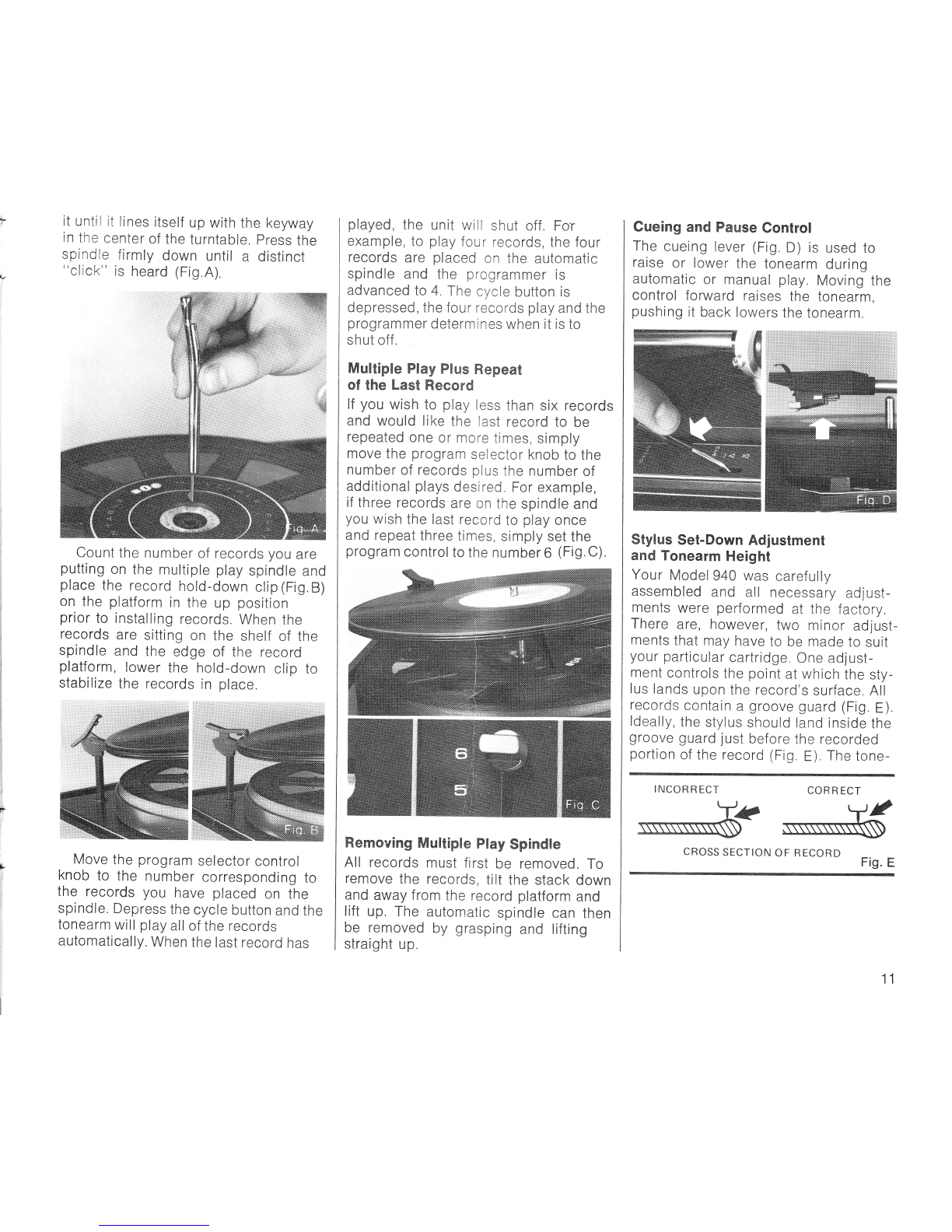
it until it lines itself up with the keyway
in the center of the tu rntable, press the
spindle firmly down until a distinct
"click" is heard (Fig.A)
Count the number of records you are
putting on the multiple play spindle and
place the record hold-down clip (Fig. B)
on the platform in the up position
prior to installing records. When the
records are sitting on the shelf of the
spindle and the edge of the record
platform, lower the hold-down clip to
stabilize the records in place.
Move the program selector control
knob to the number corresponding to
the records you have placed on the
spindle. Depress the cycle button and the
tonearm will play all of the records
automatically. When the last record has
played, the unit will shut off. Fo'r
example, to play f ou r records, the four
records are placed on the automatic
spindle and the programmer is
advanced Io 4 The cycle button is
depressed, the four records play and the
programmer determines when it is to
shut off .
Multiple Play Plus Repeat
of the Last Record
lf you wish to play less than six records
and would like the last record to be
repeated one or more times, simply
move the program selector knob to the
number of records plus the number of
adCitional plays desired. For example,
if three records are on the spindle and
you wish the last record to play once
and repeat three times, simply set the
program control to the number 6 (Fig. C).
Removing Multiple Play Spindle
All records must first be removed. To
remove the records, tilt the stack down
and away from the record platform and
lift up. The automatic spindle can then
be removed by grasping and lifting
straight up.
Cueing and Pause Control
The cueing lever (Fig. D ) is used to
raise or lower the tonearm during
automatic or manual play. Moving the
control forward raises the tonearm,
pushing it back lowers the tonearm.
Stylus Set-Down Adjustment
and Tonearm Height
Your Model 940 was carefully
assembled and all necessary ad just-
ments were performed at the factory.
There are, however, two minor adjust-
ments that may have to be made to suit
your particular cartridge. One adjust-
ment controls the point at which the sty-
lus lands upon the record's surface. All
records contain a groove guard (Fig E ).
ldeally, the stylus should land inside the
groove guard just bef ore the recorded
portion of the record (Fig E) The tone-
INCORRECT CORRECT
G
CROSS SECTION OF R ECORD Fig. E
11
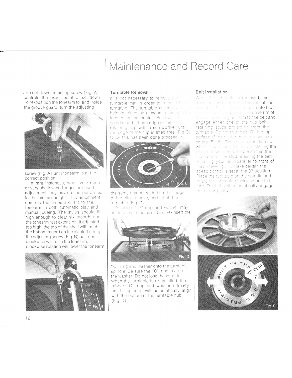
arm set-dor,vn ad justing screw (Fig A )
controls the exact point of set-down
To re-position the tonearm to land inside
the groove guard, tu rn the ad justing
screw (Fig A) until tonearrn is at the
correct position,
ln rare instances, when verY deeP
or very shallow cartridges are used
adjustment may have to be performed
to the pickup height This adlustnrent
controls the amount of lift to the
tonearm in both autonratic play and
manual cueing The stylus shculC lift
high encugh to clear six records and
the tonearm rest extension. lf ad justed
too high,the top of the shellwill touch
the bottom record on the stack. Turning
the adjusting screw (Fig B) counter-
clockwise will raise the tonearm;
clockwise rotation will lower the tonearrn,
%.
12
M aintenance and Record Cere
Turntable Removal
It is nct necessarv to re(',: , : ' :
iurntacie mat in order to i-e^--,:
turntarle The turntable asss-:,
tselt lnstalIation
rreld rn piace by a nylcn r3 --
lo,cateci in tlte center, Rer- a . =
sci^Cl: a^C lr{i one edge of tr:
feiai.,l: 6liD lVith a SCfewg'ri,,'e"
i'^^ ^^-^ ^:
tn? ec le ci the clip is lifted f ree
O^o?:1.= -as been done proceeJ
the s?^-3 rnanner with the other edce
n4 Lnn niit-t
(-/, . = u;,u ''3,llOVe, and lift Off tne
iult:ao: 'F g D)
A i-uocer "C" ring and r,vasher ma)'
cc-re cfi \^,'tn the turntable Re-insert ihe
''O ' ring and washer ortto the turntable
spindle Ee sure the "O" ring ts atcp
the r,vasher Do not lose these partsl
When the turntable is re-installed, the
rubber "O ring and washer (already
on the spindle) will autonnatically aiign
with the bottom of the turntable hub
(Fig D )
J
l : :-./
: -: - CVed, the
- 3 rim of the
: ::1. cnto the
^ : o rive rim of
','?t= a='-,ain the
:: ?'-^= 33 position,
\Jv
: clccK\\'ise one full
au.cmatically engage
3,
-3".
Re-install the Turntable
Retaining *C" Clip
The turntable "C" clip has a projection on
both the top and bottom, THIS PROJEC-
TICN MUST FIT FULLY INTO THE SLOT
CF TFIE TURNTABLE SPINDLE (Fig F,
page12).
Lubrication
All pivot points and bearing surfaces
have been lubricated at the factory and
will seldom, if ever, require f urther
attention Should lubrication be
required, we recommend this be
performed by B"l.C or one of its
authorized service stations. lf you prefer
doing this yourself, we recommend
you purchase a Tech nical Service
Manual which provides full details and
explicit instructions on this entire
su bj ect
Record Care
Keep the cartridge and stylus clean
and replace if worn. Periodically have
the stylus inspected by your dealer
Retu rn all records to their protective
sleeves and jackets Do not leave records
on the tu rntable f or long periods, if not
in use.
Store vertically rather than horizontally
or flat. lf possible, store records at
average room temperatures, Do not
perr-nit them near or in contact with heat
producing devices, such as radiators,
electronic equipment, amplifiers, etc.
Excessive temperatures tend to cause
warpage of records. Avoid hand ling the
groove surfaces as this will deposit a
film of oil on the grooves. Hold records
by their outer edges when mounting or
removing from turntable to keep
records clean
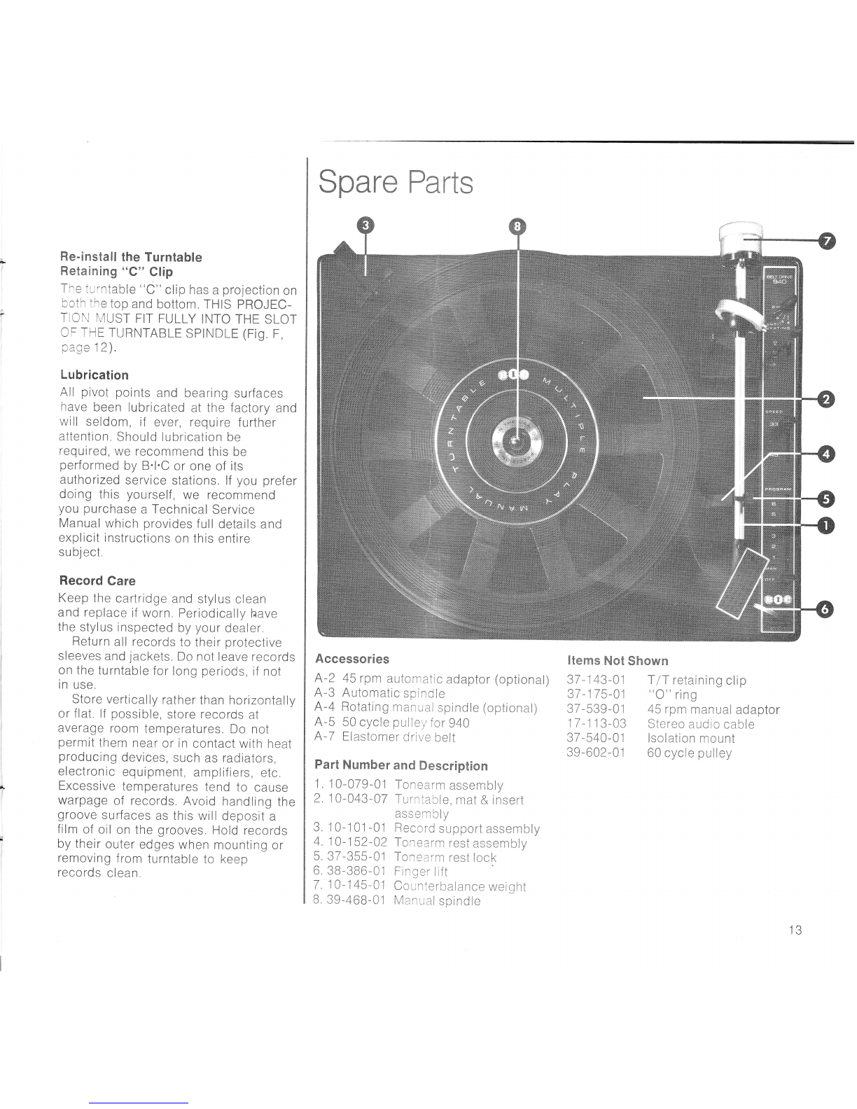
Spare Parts
Accessories
A-2 45 rpnr automatic adaptor (optional)
A-3 Automatic spindle
A-4 Rotating man ual spindle (optional)
A-5 50 cycle pulley for 940
A-7 Elastomer drive belt
Part Number and Description
1, 1 0-079-01 Tonearm assenrbly
2. 10-043 -07 Turntable, rnat & insert
asserrbly
3 10-101-01 Record support assennbly
4. 1 0- 1 52-02 Ton earrn rest assem bly
5 37-355-C1 Tonearrn rest lock
6 3B-386-C1 Finger lift
7 10-1 45-Al Counterbalance weight
8 39-468-01 Man ual spindle
T lT retaining clip
((O" ring
45 rpm manual adaptor
Stereo aud io cable
lsolation rnount
60 cycle pulley
Items Not Shown
37 -143-01
37 -175-01
37 -539 - 01
17 -1 1 3-03
37 -540- 01
39-602-01
13
Spare Parts
To insu re positive identif ication of you r
unit when ordering spare parts, please
quote all the information printed on the
foil label underneath the unit plate or on
the outside of the packing carton. Also
quote the part number if listed, the
color, the voltage and the power supply
frequency.
Please address inquiries for spares and
service to your dealer.
ln case of diff iculty, send your inquiry to:
British lndustries Company
Westbury, New York, 11590
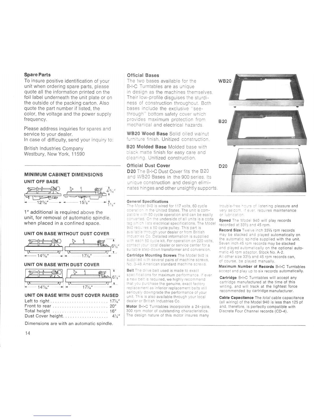
MINIMUM CABINET DIMENSIONS
UNIT OFF BASE
E-ffi-'
@
[* 121X0"
-
a
4t%u"
Y
-1 5 il
t,g
1" additional is required above the
unit, for removal of automatic spindle,
when placed in a conf ined space.
UNIT ON BASE WITHOUT DUST COVER
6%u"
4- 141Y.,0" -l r- -17/to"
UNIT ON BASE WITH DUST COVER -r
6%"
141X0"
UNIT ON BASE WITH DUST COVER RAISED
Left to right . 17X0"
Front to rear 20"
Total he ig ht 1 6"
Dust Cover height 4)4"
Dimensions are with an automatic spindle.
-17/to"
14
Official Bases
The two bases available f o r the
B.l.C Turntables are as unique
in design as the machines themselves.
Their low-profile disguises the sturdi-
ness of construction throughout. Both
bases include the exclusive "see-
through" bottom safety cover which
provides rnaximum protection from 820
rnechanical and electrical hazards
WB20 Wood Base Solid oiled walnut
furniture finish. Unitized construction.
F20 Molded Base Molded base with
black rnatte finish for easy care and
cleaning. Unitized construction.
Official Dust Cover D20
D20 The B.l.C Dust Cover f its the B 20
and WB 20 Bases in the 900 series lts
unique construction and design elimi-
nates hinges and other unsightly supports,
wB20
Ge ne ra I Specif ications
The N,'lcdei 940 is wired for 117 volts,60 cycle
olei'ai:cn in the United States, The unit is com-
patible'.',,;th 50 cycle operation and can be easily
converied, On the underside of all units is a code
iag',,,'hlch ltsis electrical specifications. The Model
940 requ:i'es a 50 cycle pulley. This part is
avaiiacle ihrough your dealer or f ronr British
lndustr:es Co, Detailed information is supplied
tirith each 50 cycle kit. For operation on 220 volts,
contact your local dealer or service center f or a
suitable step-down transformer and conversion.
Cartridge Mounting Screws The Model 940 is
suppiied rvith several pairs of machine screws,
No. 3-48 Anrerican standard machine screv/s,
Belt The cirive belt used is made to exact
spectfications for maximum perforrnance. lf ever
a nev/ belt is required, we highly recommend
that you purchase the genuine, exact factory
replacement as inferior replacement belts will
seriously downgrade the performance of your
unit. This is also available through your local
dealer or British lndustries Co.
Motor B.l.C Turntables incorporate a 24-pole,
300 rpm motor of outstanding ch.aracteristics.
The design nature of this motor insures many
trouble-fi-ee;3urs of listening pleasure and
very seldorr if e';er, requires maintenance
or lubrication.
Speed The Model 940 will play records
recorded aI 331/z and 45 rpm.
Record Size Twelve inch 337: rpm records
may be stacked and played automatically on
the automatic spindle supplied with the unit.
Seven inch 45 rpm records may be stacked
and played automaticaliy on the optional auto-
matic 45 rpm adaptor, Stock No. A-2.
All other size 33Vs and 45 rpm records can,
of course, be played manually.
Maximum Number of Records B.l.C Turntables
accept and play up to six records automatically.
Cartridge B.l.C Turntables will accept any
cartridge manufactured at the time of this
writing, and will track at the lightest iorce
recommended by cartridge manufacturer,
Gable Capacitance The lotal cable capacitance
(all wiring) of the Model 940 is less than 125 pf
and, therefore, is perfectly compatible with
Discrete Four Channel records (CD-a).
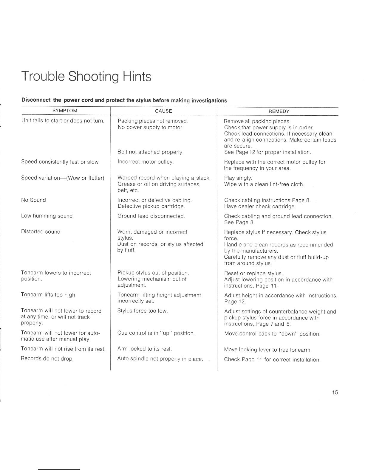
Trouble Shooting Hints
Disconnect the power cord and protect the stylus before making investigalions
SYMPTOM
Unit fails to start or does not turn.
Speed consistently fast or slow
Speed variation-(Wow or flutter)
No Sound
Low humming sound
Disto rted sou nd
Tonearm lowers to incorrect
position.
Tonearm lifts too high.
Tonearm will not lower to record
at any time, or will not track
properly.
Tonearm will not lower for auto-
matic use after manual play.
Tonearm will not rise from its rest.
Records do not drop.
Packing pieces not removed,
No power supply to motor,
Belt not attached properly.
lncorrect motor pulley.
Warped record when playing a stack.
Grease or oil on driving surfaces,
belt, etc.
lncorrect or defective cabling.
Defective pickup cartridge.
Ground lead disconnected,
Worn, damaged or incorrect
stylus.
Dust on records, or stylus affected
by f luff
Pickup stylus out of position.
Lowering mechanism out of
ad justm ent.
Tonearm lifting height adjustment
incorrectly set.
Stylus force too low.
Cue control is in "up" position.
Arm locked to its rest.
Auto spindle not properly in place
REMEDY
Remove all packing pieces.
Check that power supply is in order.
Check lead connections. lf necessary clean
and re-align connections. Make certain leads
are secure.
See Pag e 12 for proper installation.
Replace with the correct motor pulley for
the f req uency in you r area.
Play singly.
Wipe with a clean lint-f ree cloth.
Check cabling instructions Page B.
Have dealer check cartridge.
Check cabling and ground lead connection.
See Page B.
Replace stylus if necessary. Check stylus
fo rce.
Handle and clean records as recommended
by the manufacturers.
Carefully remove any dust or fluff build-up
from around stylus.
Reset or replace stylus.
Adjust lowering position in accordance with
instructions, Page 1 1.
Adjust height in accordance with instructions,
Page 12.
Adjust settings of counterbalance weight and
pickup stylus force in accordance with
instructions, Page 7 and B .
Move control back to "down" position.
Move locking lever to f ree tonearm.
Check Page 11 for correct installation.
CAUSE
15

@oo
BRlrlsH INDUSTRIES COMPANY, westbury, N.y. 1 1590 u.s.A. I oiuirion of Avnet, tnc.
:;-?;i;;."-.r"tBritishlndustriesco.,westburv,N.Yll5g0.DivisionofAvnel,rnc.copyrishtrsts. @
Table of contents
Other BIC Turntable manuals


