BIC 980 User manual

0O0
Multiple
Play
Manual
Turntables


Features
of
Models
980
and
960
BTC
Multiple
Play
Manual
Turntables
1.
Cycle
button—feather
touch
control
activates
all
turntable
functions.
2.
Tone
arm
finger
lift—human-
engineered
for
positive,
secure
manual
handling
of
tonearm.
3.
Programmer
selector—selects
manual
or
automatic
operation,
shut-off
and
number
of
plays.
4.
Initial
15
degree
tracking
angle
adjustment—permits
pivoting
of
entire
shell
for
parallel
alignment
and
15
degree
tracking
angle
of
stylus
assembly,
regardless
of
shape
or
depth
of
cartridge.
5.
Knurled
cartridge
shell
retaining
nut—locks
shell
firmly
in
proper
alignment.
6.
Cartridge
shell
connector—male
female
connection
for
positive
electrical
contact.
7.
Tonearm
rest—extended
for
stylus
and
cartridge
protection.
8.
Tonearm
lock—prevents
damage
during
transport
or
accidental
jarring.
9.
Speed
selector—shifts
drive
belt
for
33V3
rpm
or
45
rpm
rotation.
10.
Tonearm
set-down
adjustment—
adjusts
set-down
position
of
stylus
at
edge
of
record.
11.
Cueing
rate
adjustment—varies
cueing
speed
in
accordance
with
user
preference
or
to
suit
climatic
conditions.
12.
Force
calibration
scale—expanded
scale
for
precision
setting
of
stylus
tracking
and
anti-skate
forces.
13.
Tracking
force
adjustment
lever—
sets
desired
tracking
force
from
0
to
4
grams.
14.
Anti-skate
force
adjustment
lever
—sets
corresponding
anti-skate
force—may
be
set
in
tandem
with
tracking
force
adjustment
or
independently.
15.
Cueing
lever—initiates
safe,
damped
lowering
or
raising
of
tone
arm
or
can
be
used
as
pause
control.
16.
Stylus
mode
selector—selects
proper
skating
force
reference
for
elliptical
or
conical
styli;
elimin¬
ates
the
need
for
two
calibration
scales.
17.
Isolated
tonearm
counterweight
permits
dynamic
zero
balancing
of
entire
tonearm,
while
insuring
maximum
damping.
18.
Precision
gimbal
bearings—for
minimal
horizontal
and
vertical
pivotal
friction.
19.
12"
diecast
platter—solid,
one-
piece
precision
casting
has
computer
optimized
mass.
20.
Manual
spindle—rotates
with
platter
during
single-play
operation.
21.
Automatic
spindle—supports
records
during
automatic
record
play.
22.
Record
support—platform
stabilizes
records
placed
on
spindle
for
safe
two-point
support
during
automatic
play.
23.
Solid
state
electronic
pitch
control
(Model
980
only)—
sets
precise,
unvarying
turntable
speed
and
permits
±3%
variation
from
nominal
speed.
24.
Illuminated
stroboscope
(Model
980
only)—used
in
con¬
junction
with
electronic
pitch
control.
Visible
during
record
play.
25.
Auto/Manual
cartridge
angle
selector—permits
proper
15
degree
compensation.
26.
Elastomer
suspension
mounts
—correlated
to
the
mass
of
the
turntable
assembly
for
maximum
isolation
from
external
shock
in
all
planes.
27.
All
electronic
drive
signal
generator
(Model
980
only)—
modular
etched
circuit
generates
stable
60
Hz.
signal
to
drive
synchronous
motor.
28.
Synchronous
24
pole
motor—oper¬
ates
at
slow,
vibration-free
300
rpm.

Index
PAGE
Set-Up
Procedures
Operating
Procedures
There
are
many
playing
and
operating
options
built
into
your
B-l-C
Multiple
Play
Manual
Turntable,
plus
a
number
of
unique
control
features.
These
are
sum¬
marized
on
this
page
—and
specific
operating
instruc¬
tions
for
the
various
playing
options
are
detailed
on
the
pages
indicated.
Normal
maintenance
procedures
are
also
described
and
listed,
along
with
a
set
of
specifications
which
will
be
of
interest
to
the
audio
enthusiast.
4
How
to
properly
unpack
the
unit
5
Note
the
accessories
supplied
5
Installing
the
turntable
on
the
base
5
Proper
mounting
of
the
cartridge
in
the
tonearm
shell
6
How
to
properly
orient
and
position
the
cartridge
6
Connecting
the
shell
with
the
tonearm
7
Installing
the
counterweight
7
Selecting
proper
stylus
setting
7
Adjusting
proper
tracking
and
anti-skate
forces
7
Leveling
the
cartridge
shell
7
Installation
of
audio
cable
and
ground
connection
'
8
.
Connecting
to
AC
power
8
Manual
play
of
a
single
record
9
Programmed
repeat
play
of
a
single
record
10
Automatic
play
of
a
single
record
10
Automatic
play
of
multiple
records
10
Multiple
play
of
records
plus
repeat
of
last
record
11
Use
of
cueing
and
pause
control
11
Adjusting
the
cueing
rate
11
Adjustment
of
stylus
set-down
point
11
Turntable
removal
12
Drive
belt
installation
12
Lubrication
instructions
13
Tips
on
record
care
13
Spare
parts
list
13
Accessories
13
General
specifications
14
Trouble-shooting
hints
15
Set-Up
Procedure
■
*©f
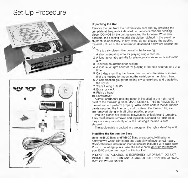
Unpacking
the
Unit
Remove
the
unit
from
the
bottom
styrofoam
filler
by
grasping
the
unit
plate
at
the
points
indicated
on
the
top
cardboard
packing
piece.
DO
NOT
lift
the
unit
by
grasping
the
tonearm.
Whenever
possible,
the
packing
material
should
be
retained
in
the
event
re¬
shipment
is
necessary.
In
any
event,
do
not
discard
the
packing
material
until
all
of
the
accessories
described
below
are
accounted
for.
The
top
styrofoam
filler
contains
the
following:
1.
A
short
manual
spindle
for
playing
single
records.
2.
A
long
automatic
spindle
for
playing
up
to
six
records
automatic¬
ally.
3.
Tonearm
counterbalance
weight.
4.
A
manual
45
rpm
adaptor
for
playing
large
hole
records,
one
at
a
time.
5.
Cartridge
mounting
hardware;
this
contains
the
various
screws
that
are
needed
for
mounting
the
cartridge
in
the
pickup
head.
6.
A
combination
gauge
for
setting
stylus
overhang
and
paralleling
the
stylus.
7.
Transit
wing
nuts
(2).
8.
Extra
lock
nut.
9.
Pick-up
head.
10.
S
crewdriver
A
small
cardboard
packing
piece
is
installed
in
the
right-hand
pivot
of
the
tonearm
gimbal.
MAKE
CERTAIN
THIS
IS
REMOVED,
or
the
unit
will
not
perform
properly.
Also,
make
certain
that
all
rubber
bands
securing
the
line
cord,
audio
cables,
the
tonearm
tie,
etc.,
are
removed
along
with
all
other
packing
pieces.
Packing
pieces
are
installed
between
the
unit
plate
and
turntable.
They
must
also
be
removed
and,
if
possible,
should
be
retained
as
they
are
a
very
important
part
of
the
packing
if
the
unit
is
ever
shipped.
The
audio
cable
is
packed
in
a
wedge
on
the
right
side
of
the
unit.
Installing
the
Unit
on
the
Base
Both
the
B-20
Base
and
WB-20
Base
are
supplied
with
a
bottom
safety
cover
which
eliminates
any
possibility
of
mechanical,
hazard.
Comprehensive
installation
instructions
are
included
with
each
base.
Prior
to
mounting
upon
a
base,
the
audio
cable
must
be
installed
on
your
BTC
unit
as
per
page
8
of
this
booklet.
PROPER
INSTALLATION
IS
EXTREMELY
IMPORTANT.
DO
NOT
INSTALL
THIS
UNIT
ON
ANY
DEVICE
OTHER
THAN
THE
OFFICIAL
B-20
OR
WB-20
BASES.
5
Cartridge
Installation
and
Adjustment
In
order
to
take
advantage
of
the
many
features
of
the
B-l-C
tonearm,
it
is
extremely
important
that
the
cartridge
be
properly
installed
and
the
various
adjustments
pertaining
to
the
cartridge
be
made.
These
are
described
below:
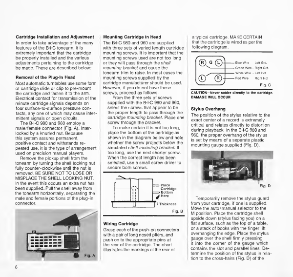
Removal
of
the
Plug-In
Head
Most
automatic
turntables
use
some
form
of
cartridge
slide
or
clip
to
pre-mount
the
cartridge
and
fasten
it
to
the
arm.
Electrical
contact
for
transmission
of
the
minute
cartridge
signals
depends
on
four
surface-to-surface
pressure
con¬
tacts,
any
one
of
which
may
cause
inter¬
mittent
signals
or
open
circuits.
The
B-l-C
980
and
960
employ
a
male/female
connector
(Fig.
A),
inter¬
locked
by
a
knurled
nut.
Because
this
system
assures
permanent,
positive
contact
and
withstands
re¬
peated
use,
it
is
the
type
of
arrangement
used
on
precision
manual
players.
Remove
the
pickup
shell
from
the
tonearm
by
turning
the
shell
locking
nut
fully
counter-clockwise
until
the
nut
is
removed.
BE
SURE
NOT
TO
LOSE
OR
MISPLACE
THE
SHELL
LOCKING
NUT.
In
the
event
this
occurs
an
extra
nut
has
been
supplied.
Pull
the
shell
away
from
the
tonearm
horizontally,
separating
the
male
and
female
portions
of
the
plug-in
connector.
6
Mounting
Cartridge
in
Head
The
B-l-C
980
and
960
are
supplied
with
three
sets
of
varied
length
cartridge
mounting
screws.
It
is
important
that
the
mounting
screws
used
are
not
too
long
or
they
will
pass
through
the
shell
mounting
bracket
and
cause
the
tonearm
trim
to
raise.
In
most
cases
the
mounting
screws
supplied
by
the
cartridge
manufacturer
should
be
used.
However,
if
you
do
not
have
these
screws,
proceed
as
follows:
From
the
three
sets
of
screws
supplied
with
the
B-l-C
980
and
960,
select
the
screws
that
appear
to
be
the
proper
length
to
pass
through
the
cartridge
mounting
brackef.
Place
one
screw
through
the
bracket.
To
make
certain
it
is
not
too
long,
place
the
bottom
of
the
cartridge
as
shown
in
the
diagram
below
and
note
whether
the
screw
projects
below
the
simulated
shell
mounting
bracket.
If
too
long,
use
the
next
shorter
screw.
When
the
correct
length
has
been
selected,
use
a
small
screw
driver
to
secure
both
screws.
Cartridge
=
Bottom
^
Here
Wiring
Cartridge
Grasp
each
of
the
push-on
connectors
with
a
pair
of
long
nosed
pliers,
and
push
on
to
the
appropriate
pins
at
the
rear
of
the
cartridge.
The
chart
illustrates
the
markings
at
the
rear
of
atypical
cartridge.
MAKE
CERTAIN
that
the
cartridge
is
wired
as
per
the
following
diagram.
®
G
©1
-
B
,ueWire
LeftGrd
-Green
Wire=-
Right
Grd.
©
®
I
—
Red
Wire
=
R
ght
Hot
^-
'
Fig.
C
CAUTION—Never
solder
directly
to
the
cartridge.
DAMAGE
WILL
OCCUR
Stylus
Overhang
The
position
of
the
stylus
relative
to
the
exact
center
of
a
record
is
extremely
critical
and
relates
directly
to
distortion
during
playback.
In
the
B-l-C
980
and
960,
the
proper
overhang
of
the
stylus
is
set
by
means
of
a
separate
plastic
mounting
gauge
supplied
(Fig.
D).
Fig.
D
Temporarily
remove
the
stylus
guard
from
your
cartridge,
if
one
is
supplied.
Move
the
auto/manual
selector
to
the
M
position.
Place
the
cartridge
shell
upside
down
(stylus
facing
you)
on
a
flat
surface,
such
as
the
top
of
a
table,
or
a
stack
of
books
with
the
finger
lift
overhanging
the
edge.
Place
the
stylus
gauge
over
the
shell
firmly
pressing
it
into
the
corner
of
the
gauge
which
contains
the
slot
and
parallel
lines.
De¬
termine
the
position
of
the
stylus
in
rela¬
tion
to
the
cross-hairs
(Fig.
D)
of
the
gauge.
Loosen
the
cartridge
mounting
screws
and
move
the
cartridge
until
the
stylus
tip
lies
directly
under
the
center
of
the
cross-hairs.
Remove
the
gauge
from
the
shell
and
re-tighten
the
mounting
screws.
Re-check
alignment,
using
the
gauge,
to
make
sure
the
cartridge
has
not
shifted
during
the
tightening
process.
Attach
Shell
to
Tonearm
Line
up
the
hole
in
the
rear
of
the
shell
with
the
pivot
pin
on
the
tonearm
and
engage
the
plug-in
socket
of
the
pickup
head
with
the
pickup
arm
(Fig.
A,
Pg.
6).
(The
connector
in
the
tonearm
is
a
floating,
self-aligning
connector.)
Press
the
pickup
head
into
the
tonearm.
Re-install
the
head
locking
nut
but
do
not
fully
tighten.
Counterweight
Installation
The
counterweight
should
be
installed
on
the
tonearm
in
the
following
manner:
Place
the
counterweight
at
the
end
of
the
tonearm,
with
the
knurl
facing
the
rear,
and
rotate
it
in
a
counter-clock¬
wise
direction
(Fig.
A).
The
counter¬
weight
must
be
assembled
and
taken
off
the
tonearm
only
by
a
winding
action
—not
by
directly
pushing
or
pull¬
ing.
Rotate
the
platter
in
a
clockwise
direction
approximately
5
turns
to
make
certain
that
the
mechanism
is
free
and
the
unit
is
not
in
cycle.
Also,
make
cer¬
tain
that
the
cueing
lever
is
in
the
play
position.
With
the
tonearm
released
from
its
locked
position
and
both
anti¬
skate
and
tracking
force
levers
set
to
0
(zero),
continue
to
rotate
the
counter¬
weight
until
the
tonearm
is
perfectly
balanced,
floating
parallel
to
the
turn¬
table.
When
this
is
accomplished,
the
tonearm
will
be
at
the
approximate
level
of
the
extension
on
the
tonearm
pickup
rest.
Selecting
Proper
Anti-Skate
Mode
The
physical
and
geometric
relation¬
ships
of
all
offset
tonearms
give
rise
to
an
inward
force
during
record
play
which
applies
lateral
forces
against
the
inner
groove
wall
of
a
record.
This
force
is
called
“skating”
and
must
be
coun¬
tered
by
an
equal
and
opposite
force
if
minimum
record
wear
and
optimum
tracking
is
to
be
achieved.
The
anti-skating
systems
on
the
980
and
960
are
unique
in
a
number
of
respects.
On
all
automatic
turntables,
and
even
on
many
manual
players,
a
double
scale
is
employed
to
permit
set¬
tings
for
the
differences
in
the
amount
of
force
needed
when
using
an
elliptical
or
conical
stylus.
Not
only
is
this
con¬
fusing
and
difficult
to
set,
but
in
actual
fact,
this
method
involves
a
compromise
since
one
force
is
being
used
to
create
both
compensations.
In
the
Models
980
and
960,
the
reference
point
for
elliptical
and
conical
styli
is
preset
by
a
separate
function
lever
(Fig.
B).
Shift
the
conical
o
/elliptical
o
stylus
mode
selector
to
the
appropriate
posi¬
tion—conical
or
elliptical,
depending
upon
the
type
of
stylus
used
in
your
car¬
tridge.
For
other
types
of
styli,
such
as
Shibata
or
CD-4
cartridges,
consult
the
cartridge
manufacturer’s
recommenda¬
tion
for
anti-skating
calibration.
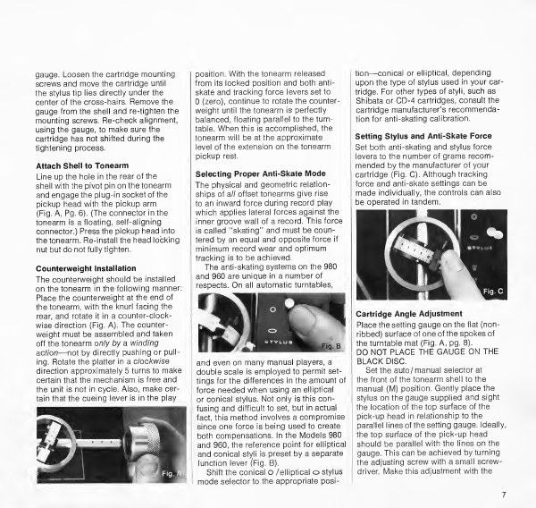
Setting
Stylus
and
Anti-Skate
Force
Set
both
anti-skating
and
stylus
force
levers
to
the
number
of
grams
recom¬
mended
by
the
manufacturer
of
your
cartridge
(Fig.
C).
Although
tracking
force
and
anti-skate
settings
can
be
made
individually,
the
controls
can
also
be
operated
in
tandem.
Cartridge
Angle
Adjustment
Place
the
setting
gauge
on
the
flat
(non-
ribbed)
surface
of
one
of
the
spokes
of
the
turntable
mat
(Fig.
A,
pg.
8).
DO
NOT
PLACE
THE
GAUGE
ON
THE
BLACK
DISC.
Set
the
auto/
manual
selector
at
the
front
of
the
tonearm
shell
to
the
manual
(M)
position.
Gently
place
the
stylus
on
the
gauge
supplied
and
sight
the
location
of
the
top
surface
of
the
pick-up
head
in
relationship
to
the
parallel
lines
of
the
setting
gauge.
Ideally,
the
top
surface
of
the
pick-up
head
should
be
parallel
with
the
lines
on
the
gauge.
This
can
be
achieved
by
turning
the
adjusting
screw
with
a
small
screw¬
driver.
Make
this
adjustment
with
the
tonearm
elevated
over
the
gauge
to
avoid
any
damage
to
your
stylus
(Fig.
A).
Lower
to
gauge
and
re-check.
Once
the
correct
position
is
achieved,
fully
tighten
the
pick-up
head
locking
nut.
Connecting
Your
B
I
C
Turntable
to
an
Audio
Amplifier
Audio
Cable
Models
980
and
960
are
supplied
with
a
double
ended
color
coded
audio
cable.
This
cable
was
selected
to
provide
minimum
capacitive
loading
effects
on
high
frequency
response
of
your
cartridge.
This
is
especially
important
if
your
cartridge
is
capable
of
playing
CD-4
discrete
four
channel
recordings.
If
longer
cables
are
required,
make
certain
they
are
of
a
low
capacity
type
or
check
with
the
manufacturer
of
your
cartridge
for
his
recommendations
re¬
garding
cable
type
and
length
limitations.
Unravel
the
cable
and
insert
one
of
the
plugs
into
the
phono
socket
marked
“R"
on
the
underside
of
the
unit.
Insert
the
other
color
plug
into
the
socket
marked
“L”.
Make
certain
the
plugs
are
pressed
all
the
way
in
(Fig.
B).
Feed
the
cable,
line
cord
and
black
ground
lead
through
the
base
as
shown
on
the
base
instruction
sheet.
Note
the
color
of
the
plug
going
to
"R"
on
the
unit
and
insert
the
same
color
at
the
other
end
into
the
right
channel
of
the
amplifier.
Follow
the
same
procedure
for
the
left
channel.
Amplifier
Connections
If
you
are
using
a
magnetic
phono
cartridge,
insert
the
phono
plugs
into
the
space
provided
at
the
rear
of
the
amplifier
marked
“phono
low
level"
or
“phono
MAG”
(Fig.
C).
If
you
are
using
a
ceramic
cartridge,
insert
the
audio
cable
plugs
into
the
high
level
input
of
the
amplifier
(phono
CER).
The
ground
wire
supplied
with
the
turntable
should
be
connected
to
a
suit¬
able
“ground”
point
on
the
metal
chassis
of
your
amplifier.
Most
am¬
plifiers
provide
a
convenient
terminal
on
the
rear
panel
for
this
purpose.
Fail¬
ure
to
ground
this
wire
will
result
in
an
inordinately
high
hum
level
when
attempting
to
play
records.
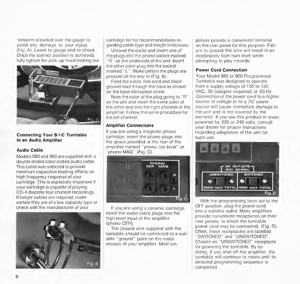
Power
Cord
Connection
Your
Model
980
or
960
Programmed
Turntable
was
designed
to
operate
from
a
supply
voltage
of
105
to
130
VAC,
50
(adapter
required)
or
60
Hz.
Connection
of
the
power
cord
to
a
higher
source
of
voltage
or
to
a
DC
power
source
will
cause
immediate
damage
to
the
unit
and
is
not
covered
by
the
warranty.
If
you
use
this
product
in
areas
powered
by
220
or
240
volts,
consult
your
dealer
for
proper
instructions
regarding
adaptation
of
the
unit
for
such
use.
With
the
programming
lever
set
to
the
OFF
position,
plug
the
power
cord
into
a
suitable
outlet.
Many
amplifiers
provide
convenient
receptacles
on
their
rear
panels,
to
which
the
turntable
power
cord
may
be
connected,
(Fig.
D).
Often,
these
receptacles
are
labelled
“SWITCHED”
and
“UNSWITCHED”.
Choose
an
“UNSWITCHED”
receptacle
for
powering
the
turntable.
By
so
doing,
if
you
shut
off
the
amplifier,
the
turntable
will
continue
to
rotate
until
its
selected
programming
sequence
is
completed,
Operating
Procedure
Before
attempting
to
play
records
on
your
B-l-C
Belt
Drive
Programmed
Turn¬
table,
make
certain
that
the
tonearm
retaining
lock
(Fig.
A)
bn
the
tonearm
rest
is
loosened
by
moving
it
to
the
right
with
forefinger.
Most
cartridges
are
fit¬
ted
with
a
stylus
guard
or
protective
cover.
Make
certain
this
cover
is
re¬
moved
or
pivoted
so
as
to
expose
the
stylus
tip.
Set
the
speed
selector
lever
(Fig.
B)
for
the
type
of
record
you
wish
to
play.
The
Models
980
and
960
play
12"
33
rpm
records
when
the
speed
selector
lever
is
set
for
33;
7"
45
rpm
records
when
set
to
45.
When
playing
a
45
rpm
record,
install
the
manual
45
rpm
adaptor
over
the
manual
spindle,
which
should
be
placed
in
the
center
hole
of
the
turntable.
Place
a
record
on
the
turntable
and
make
sure
the
auto/manual
selector
located
on
the
front
of
the
cartridge
shell
is
set
to
the
correct
position.
If
playing
one
record
move
the
auto/
manual
selector
(Fig.
A)
to
reveal
the
letter
“M”;
if
playing
more
than
one
record,
move
the
compensator
to
reveal
the
letter
“A”.
An
optional
multiple
play
45
rpm
adaptor
is
available.
Place
this
adaptor
over
the
automatic
spindle
to
play
up
to
six
records-.
(See
page
10.)
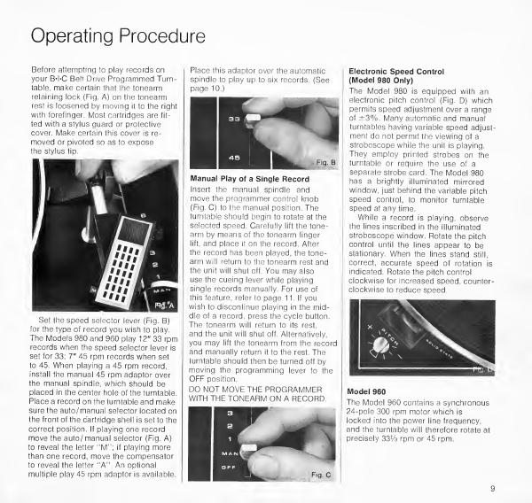
Manual
Play
of
a
Single
Record
Insert
the
manual
spindle
and
move
the
programmer
control
knob
(Fig.
C)
to
the
manual
position.
The
turntable
should
begin
to
rotate
at
the
selected
speed.
Carefully
lift
the
tone¬
arm
by
means
of
the
tonearm
finger
lift,
and
place
it
on
the
record.
After
the
record
has
been
played,
the
tone¬
arm
will
return
to
the
tonearm
rest
and
the
unit
will
shut
off.
You
may
also
use
the
cueing
lever
while
playing
single
records
manually.
For
use
of
this
feature,
refer
to
page
11.
If
you
wish
to
discontinue
playing
in
the
mid¬
dle
of
a
record,
press
the
cycle
button.
The
tonearm
will
return
to
its
rest,
and
the
unit
will
shut
off.
Alternatively,
you
may
lift
the
tonearm
from
the
record
and
manually
return
it
to
the
rest.
The
turntable
should
then
be
turned
off
by
moving
the
programming
lever
to
the
OFF
position.
DO
NOT
MOVE
THE
PROGRAMMER
WITH
THE
TONEARM
ON
A
RECORD.
Electronic
Speed
Control
(Model
980
Only)
The
Model
980
is
equipped
with
an
electronic
pitch
control
(Fig.
D)
which
permits
speed
adjustment
over
a
range
of
±3%.
Many
automatic
and
manual
turntables
having
variable
speed
adjust¬
ment
do
not
permit
the
viewing
of
a
stroboscope
while
the
unit
is
playing.
They
employ
printed
strobes
on
the
turntable
or
require
the
use
of
a
separate
strobe
card.
The
Model
980
has
a
brightly
illuminated
mirrored
window,
just
behind
the
variable
pitch
speed
control,
to
monitor
turntable
speed
at
any
time.
While
a
record
is
playing,
observe
the
lines
inscribed
in
the
illuminated
stroboscope
window.
Rotate
the
pitch
control
until
the
lines
appear
to
be
stationary.
When
the
lines
stand
still,
correct,
accurate
speed
of
rotation
is
indicated.
Rotate
the
pitch
control
clockwise
for
increased
speed,
counter¬
clockwise
to
reduce
speed.
Model
960
The
Model
960
contains
a
synchronous
24-pole
300
rpm
motor
which
is
locked
into
the
power
line
frequency,
and
the
turntable
will
therefore
rotate
at
precisely
331/3
rpm
or
45
rpm.
9
Repeat
Play
of
a
Single
Record
Here
is
another
BTC
feature:
If
you
would
like
to
hear
one
twelve-inch
record
played
three
times,
simply
advance
the
.
programmer
to
the
number
3.
With
the
tonearm
on
the
pickup
rest,
depress
the
cycle
button
and
the
unit
will
play
the
record
three
times
and
shut
off.
Automatic
Play
of
a
Single
Record
To
play
a
single
record
automatically,
advance
the
programmer
to
the
number
1
setting
and
depress
the
cycle
button.
This
cycle
button
initiates
totally
auto¬
matic
operation.
The
arm
rises,
comes
to
the
edge
of
the
record,
and
is
gently
lowered.
At
the
end
of
record
play,
the
tonearm
returns
to
the-rest
and
the
machine
automatically
shuts
off.
If
you
move
the
programmer
to
the
number
1
setting
and
place
the
tonearm
on
the
record,
the
unit
will
not
shut
off
at
the
end
of
the
record,
but
will
continue
to
play
the
record
one
more
time.
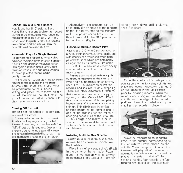
Turning
Off
the
Unit
The
unit
can
be
turned
off
at
any
time
in
one
of
two
ways:
The
cycle
button
can
be
depressed
fb
advance
the
programming
cycle
to
ttfe
next
lower
program
number
until
the
“MAN"
position
is
reached.
Depressing
the
cycle
button
once
again
will
cause
the
tonearm
to
return
to
the
tonearm
rest
and
complete
shut
off
of
the
turntable.
Alternatively,
the
tonearm
can
be
lifted
manually
by
means
of
the
tonearm
finger
lift
and
returned
to
the
tonearm
rest.
The
programming
lever
should
then
be
moved
to
the
OFF
position
to
turn
off
the
unit
(Fig.
A).
Automatic
Multiple
Record
Play
Your
Model
980
or
960
can
be
used
to
play
multiple
records
automatically,
but
with
important
differences
when
com¬
pared
with
units
which
are
commonly
categorized
as
“automatic
turntables”.
The
B-l-C
mechanism
is
exceptionally
simple,
with
a
minimum
number
of
moving
parts.
Records
are
handled
with
two-point
support,
as
opposed
to
the
umbrella-
type
single-support
system
commonly
used.
The
BTC
system
stabilizes
the
records
and
insures
reliable
dropping.
There
are
other
automatic
turntables
that
use
a
two-point
record
support
system,
but
the
980
and
960
differ
in
that
automatic
shut-off
is
completely
independent
of
the
center
automatic
spindle.
This
eliminates
the
critical
sensing
nature
of
the
spindle
and
is
one
of
the
reasons
for
the
reliable
changing
capabilities
of
the
B-l-C
unit.
This
design
also
makes
it
much
simpler
to
accommodate
records
with
variations
in
the
center
hole
diameter
or
thickness.
Installing
Multiple
Play
Spindle
To
play
up
to
six
records
in
sequence,
remove
the
short
manual
spindle
from
the
turntable.
Place
the
multiple
play
spindle
(Fig.B)
in
the
center
of
the
turntable.
Rotate
it
until
it
lines
itself
up
with
the
keyway
in
the
center
of
the
turntable.
Press
the
spindle
firmly
down
until
a
distinct
“click”
is
heard.
Count
the
number
of
records
you
are
putting
on
the
multiple
play
spindle
and
place
the
record
hold-down
clip
(Fig.
C)
on
the
platform
in
the
up
position
prior
to
installing
records.
When
the
records
are
sitting
on
the
shelf
of
the
spindle
and
the
edge
of
the
record
platform,
lower
the
hold-down
clip
to
stabilize
the
records
in
place.
Move
the
program
selector
control
knob
to
the
number
corresponding
to
the
records
you
have
placed
on
the
spindle.
Press
the
cycle
button
and
the
tonearm
Will
play
all
of
the
records
automatically.
When
the
last
record
has
played,
the
unit
will
shut
off.
For
example,
to
play
four
records,
the
four
records
are
placed
on
the
automatic
10

spindle
and
the
programmer
is
advanced
to
4.
The
cycle
button
is
depressed,
the
four
records
play
and
the
programmer
determines
when
it
is
to
shut
off.
Multiple
Play
Plus
Repeat
of
the
Last
Record
If
you
wish
to
play
less
than
six
records
and
would
like
the
last
record
to
be
repeated
one
or
more
times,
simply
move
the
program
selector
knob
to
the
number
of
records
plus
the
number
of
additional
plays
desired.
For
example,
if
three
records
are
on
the
spindle
and
you
wish
the
last
record
to
play
once
and
repeat
three
times,
simply
set
the
program
control
to
the
number
6.
(Fig.
A).
Removing
Multiple
Play
Spindle
All
records
must
first
be
removed.
To
remove
the
records,
tilt
the
stack
down
and
away
from
the
record
platform
and
lift
up.
The
automatic
spindle
can
then
be
removed
by
grasping
and
lifting
straight
up.
Cueing
and
Pause
Control
The
cueing
lever
(Fig.
B)
is
used
to
raise
or
lower
the
tonearm
during
automatic
or
manual
play.
Moving
the
control
forward
raises
the
tonearm,
pushing
it
back
lowers
the
tonearm.
Cueing
Rate
Adjustment
Today,
most
manual
and
automatic
turntables
have
a
cueing
device,
and
many
are
damped
in
both
upward
and
downward
motions.
Flowever,
whether
damping
is
accomplished
by
dashpots,
springs,
or
other
devices,
they
are
all
pre-set
at
the
factory.
This
poses
two
problems:
First,
temperature
can
affect
the
rate
of
cueing
so
that
in
hot
climates
the
rate
of
drop
is
fast
(frequently
too
fast)
and
in
cold
weather,
may
be
too
slow.
Second,
the
user
normally
has
his
own
preferences
as
to
the
speed
at
which
he
wants
the
cueing
to
operate,
and
has
been
powerless
to
control
it.
The
Models
980
and
960
incorporate,
for
the
first
time
in
any
tonearm,
a
variable
control
with
which
the
owner
can
set
the
rate
of
cueing
to
his
preference
or
compensate
for
tempera¬
ture
variations.
The
cueing
rate
can
be
increased
or
decreased
by
a
knurled
control
knob,
easily
accessible
from
the
top
surface
of
the
unit.
(Fig.
C).
Turning
the
knob
in
a
clockwise
dir¬
ection
will
decrease
the
rate
of
cueing;
counter-clockwise
rotation
will
increase
the
cueing
rate.
When
turning
the
knob
to'its
maximum
up
or
down
position,
do
not
force
it
beyond
the
stop
point.
Stylus
Set-Down
Adjustment
and
Tonearm
Height
Your
Model
980
or
960
was
carefully
assembled
and
all
necessary
adjust¬
ments
were
performed
at
the
factory.
There
are,
however,
two
minor
adjust¬
ments
that
may
have
to
be
made
to
suit
your
particular
cartridge.
One
adjust¬
ment
controls
the
point
at
which
the
sty¬
lus
lands
upon
the
record’s
surface.
All
records
contain
a
groove
guard
(Fig.'D)
Ideally,
the
stylus
should
land
inside
the
groove
guard
just
before
the
recorded
portion
of
the
record
(Fig.
D).
The
tone¬
arm
set-down
adjusting
screw
controls
the
exact
point
of
set-down.
To
re¬
position
the
tonearm
to
land
inside
the
groove
guard,
turn
the
adjusting
INCORRECT
CORRECT
A\\W\WW\\$S)
Fig.
D
CROSS
SECTION
RECORD
11

Maintenance
and
Record
Care
Belt
Installation
When
the
turntable
is
removed,
the
drive
belt
will
come
off
the
rim
of
the
turntable.
To
re-install
the
belt
onto
the
platter,
place
the
belt
on
the
drive
rim
of
the
turntable
(Fig.
E).
Grasp
the
belt
and
engage
either
one
of
the
two
belt
.
retaining
studs
projecting
from
the
turntable.
Do
not
twist
belt.
On
the
top
surface
of
the
platter
there
are
two
indi¬
cators
(Fig.
F.
These
indicators
line
up
with
the
two
studs.
When
re-installing
the
platter,
locate
the
turntable
so
that
the
indicator
for
the
stud
retaining
the
belt
is
facing
your
left
(parallel
to
front
of
machine—Fig.
F).
Make
certain
the
speed
control
is
set
at
the
33
position.
Place
the
turntable
on
the
spindle
and
rotate
the
turntable
clockwise
one
full
turn.
The
belt
will
automatically
engage
the
motor
pulley.
Turntable
Removal
It
is
not
necessary
to
remove
the
turntable
mat
in
order
to
remove
the
turntable.
The
turntable
assembly
is
held
in
place
by
a
nylon
retaining
clip
located
in
the
center.
Remove
the
spindle
and
lift
one
edge
of
the
retaining
clip
with
a
screwdriver
until
the
edge
of
the
clip
is
lifted
free
(Fig.
C).
Once
this
has
been
done
proceed
in
p
“0”
ring
and
washer
onto
the
turntable
spindle.
Be
sure
the
“O”
ring
is
atop
the
washer.
Do
not
lose
these
parts!
When
the
turntable
is
re-installed,
the
rubber
"0”
ring
and
washer
(already
on
the
spindle)
will
automatically
align
with
the
bottom
of
the
turntable
hub
B
(Fig..D).
screw
(Fig.
A)
until
tonearm
is
at
the
correct
position.
In
rare
instances,
when
very
deep
or
very
shallow
cartridges
are
used,
adjustment
may
have
to
be
performed
to
the
pickup
height.
This
adjustment
controls
the
amount
of
lift
to
the
tonearm
in
both
automatic
play
and
manual
cueing.
The
stylus
should
lift
high
enough
to
clear
six
records
and
the
tonearm
extension.
If
adjusted
too
high,
the
top
of
the
shell
will
touch
the
bottom
record
on
the
stack.
Turning
the
adjusting
screw
(Fig.
B)
counter¬
clockwise
will
raise
the
tonearm;
clockwise
rotation
will
lower
the
tonearm.
the
same
manner
with
the
other
edge
of
the
clip,
remove,
and
lift
off
the
turntable
(Fig.
D).
A
rubber
“O"
ring
and
washer
may
come
off
with
the
turntable.
Re-insert
the
12
Spare
Parts
Re-install
the
Turntable
Retaining
“C”
Clip
The
turntable
"C"
clip
has
a
projection
on
both
the
top
and
botfom.
THIS
PROJEC¬
TION
MUST
FIT
FULLY
INTO
THE
SLOT
OF
THE
TURNTABLE
SPINDLE
(Fig.
F,
page
12).
Lubrication
All
pivot
points
and
bearing
surfaces
have
been
lubricated
at
the
factory
and
will
seldom,
if
ever,
require
further
attention.
Should
lubrication
be
required,
we
recommend
this
be
performed
by
B-l-C
or
one
of
its
authorized
service
stations.
If
you
prefer
doing
this
yourself,
we
recommend
you
purchase
a
Technical
Service
Manual
which
provides
full
details
and
explicit
instructions
on
this
entire
subject.
Record
Care
Keep
the
cartridge
and
stylus
clean
and
replace
if
worn.
Periodically
have
the
stylus
inspected
by
your
dealer.
Return
all
records
to
their
protective
sleeves
and
jackets.
Do
not
leave
records
on
the
turntable
for
long
periods,
if
not
in
use.
Store
vertically
rather
than
horizontally
or
flat.
If
possible,
store
records
at
average
room
temperatures.
Do
not
permit
them
near
or
in
contact
with
heat
producing
devices,
such
as
radiators,
electronic
equipment,
amplifiers,
etc.
Excessive
temperatures
tend
to
cause
warpage
of
records.
Avoid
handling
the
groove
surfaces
as
this
will
deposit
a
film
of
oil
on
the
grooves.
Hold
records
by
their
outer
edges
when
mounting
or
removing
from
turntable
to
keep
records
clean.
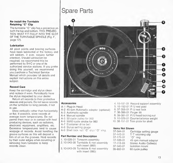
Accessories
A-1
Plug-in
Head
A-2
45
rpm
Automatic
adaptor
(optional)
A-3
Automatic
spindle
A-4
Manual
spindle
A-5
50
cycle
pul
ley
for
960
A-6
50/60
cycle
strobe
for
980
A-7
Elastomer
drive
belt
A-8
Stylus
setting
gauge
A-9
Shell
lock
nut/"C"
clip/'‘0"
ring.
Part
Number
and
Description
1.
10-028-01
Tonearm
assembly
2.
10-043-08
Turntable
&
mat
assembly
with
insert
(960)
3.
10-043-09
Turntable
&
mat
assembly
with
insert
(980)
4.10-101
-01
Record
support
assembly
5.
10-152-01
P/U
rest
post
6.
37-355-01
P/U
rest
lock
7.
38-386-01
Finger
lift
8.39-381-01
P/U
head
locking
nut
9.
10-026-01
Counterbalance
weight
10.
38-151-01
Trim
plate
for
shell
Items
Not
Shown
37-344-01
Cartridge
setting
gauge
37-143-01
T/T
retaining
clip
37-175-01
"O"
ring
37-539-01
45
rpm
manual
adaptor
17-113-03
Stereo
Audio
Cable(s)
37-540-01
Isolation
mount
39-602-01
60
cycle
pulley
13
Spare
Parts
To
insure
positive
identification
of
your
unit
when
ordering
spare
parts,
please
quote
all
the
information
printed
on
the
foil
label
underneath
the
unit
plate
or
on
the
outside
of
the
packing
carton.
Also
quote
the
part
number
if
listed,
the
color,
the
voltage
and
the
power
supply
frequency.
Please
address
inquiries
for
spares
and
service
to
your
dealer.
In
case
of
difficulty,
send
your
inquiry
to:
British
Industries
Company
Westbury,
New
York,
11590
MINIMUM
CABINET
DIMENSIONS
UNITOFF
BASE
1"
additional
is
required
above
the
unit,
for
removal
of
automatic
spindle,
when
placed
in
a
confined
space.
UNIT
ON
BASE
WITHOUT
DUST
COVER
'
|
,
*
1
■
Ut
-iu
m
[
J-
-
14%"
17%"
UNIT
ON
BASE
WITH
DUST
COVER
UNIT
ON
BASE
WITH
DUST
COVER
RAISED
Left
to
right.17%"
Front
to
rear.20"
Total
height
.16"
Dust
Cover
height.
4
Dimensions
are
with
an
automatic
spindle.
14
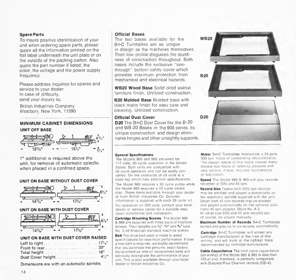
Official
Bases
The
two
bases
available
for
the
B-l-C
Turntables
are
as
unique
in
design
as
the
machines
themselves.
Their
low-profile
disguises
the
sturdi¬
ness
of
construction
throughout.
Both
bases
include
the
exclusive
“see-
through’
1
bottom
safety
cover
which
provides
maximum
protection
from
mechanical
and
electrical
hazards.
WB20
Wood
Base
Solid
oiled
walnut
furniture
finish.
Unitized
construction.
B20
Molded
Base
Molded
base
with
black
matte
finish
for
easy
care
and
cleaning.
Unitized
construction.
Motor
B-l-C
Turntables
incorporate
a
24-pole,
300
rpm
motor
of
outstanding
characteristics.
The
design
nature
of
this
motor
insures
many
trouble-free
hours
of
listening
pleasure
and
very
seldom,
if
ever,
requires
maintenance
or
lubrication.
Speed
The
Model
980
&
960
will
play
records
recorded
at
3316
and
45
rpm.
Record
Size
Twelve
inch
3316
rpm
records
may
be
stacked
and
played
automatically
on
the
automatic
spindle
supplied
with
the
unit.
Seven
inch
45
rpm
records
may
be
stacked
and
played
automatically
on
the
optional
auto¬
matic
45
rpm
adaptor,
Stock
No.
A-2.
All
other
size
3316
and
45
rpm
records
can,
of
course,
be
played
manually.
Maximum
Number
of
Records
B-l-C
Turntables
accept
and
play
up
to
six
records
automatically.
Cartridge
B-l-C
Turntables
will
accept
any
cartridge
manufactured
at
the
time
of
this
writing,
and
will
track
at
the
lightest
force
recommended
by
cartridge
manufacturer.
Cable
Capacitance
The
total
cable
capacitance
(all
wiring)
of
the
Model
980
&
960
is
less
than
125
pf
and,
therefore,
is
perfectly
compatible
with
Discrete
Four
Channel
records
(CD-4).
Official
Dust
Cover
D20
The
B-l-C
Dust
Cover
fits
the
B-20
and
WB-20
Bases
in
the
900
series.
Its
unique
construction
and
design
elimi¬
nates
hinges
and
other
unsightly
supports.
General
Specifications
The
Models
960
and
980
are
wired
for
117
volts,
60
cycle
operation
in
the
United
States.
Both
units
are
compatible
with
50
cycle
operation
and
can
be
easily
con¬
verted.
On
the
underside
of
all
units
is
a
code
tag
which
lists
electrical
specifications.
The
Model
960
requires
a
50
cycle
pulley
while
the
Model
980
requires
a
50
cycle
strobe
disc.
These
items
available
through
your
dealer
or
from
British
Industries
Co.
Detailed
information
is
supplied
with
each
50
cycle
kit.
For
operation
on
220
volts,
contact
your
local
dealer
or
service
center
for
a
suitable
step-
down
transformer
and
conversion.
Cartridge
Mounting
Screws
The
Model
980
&
960
are
supplied
with
three
pairs
of
machine
screws.
Their
lengths
are
W,
16"
and
%"
type
No.
3-48
American
standard
machine
screws.
Belt
The
drive
belt
used
is
made
to
exact
specifications
for
maximum
performance.
If
ever
a
new
belt
is
required,
we
highly
recommend
that
you
purchase
the
genuine,
exact
factory
replacement
as
inferior
replacement
belts
will
seriously
downgrade
the
performance
of
your
unit.
This
is
also
available
through
your
local
dealer
or
British
Industries
Co.
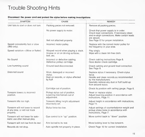
Trouble
Shooting
Hints
Disconnect
the
power
cord
and
protect
the
stylus
before
making
investigations
SYMPTOM
CAUSE
REMEDY
Unit
fails
to
start
or
does
not
turn.
Packing
pieces
not
removed.
Remove
all
packing
pieces.
No
power
supply
to
motor.
Belt
not
attached
properly.
Check
that
power
supply
is
in
order.
Check
lead
connections.
If
necessary
clean
and
re-align
connections.
Make
certain
leads
are
secure.
See
Page
12
for
proper
installation.
Speed
consistently
fast
or
slow
(960
only).
Incorrect
motor
pulley.
Replace
with
the
correct
motor
pulley
for
the
frequency
in
your
area.
Speed
variation—(Wow
or
flutter)
Warped
record
when
playing
a
stack.
Grease
or
oil
on
driving
surfaces,
belt,
etc.
Play
singly.
Wipe
with
a
clean
lint-free
cloth.
No
Sound
Incorrect
or
defective
cabling.
Defective
pickup
cartridge.
Check
cabling
instructions
Page
8.
Have
dealer
check
cartridge.
Low
humming
sound
Ground
lead
disconnected.
Check
cabling
and
ground
lead
connection.
See
Page
8.
Distorted
sound
Worn,
damaged
or
incorrect
stylus.
.
Dust
on
records,
or
stylus
affected
by
fluff.
Replace
stylus
if
necessary.
Check
stylus
force.
Handle
and
clean
records
as
recommended
by
the
manufacturers.
Carefully
remove
any
dust
or
fluff
build-up
from
around
stylus.
Cartridge
out
of
position.
Check
its
position
with
setting
gauge,
Page
6.
Tonearm
lowers
to
incorrect
position.
Pickup
stylus
out
of
position.
Lowering
mechanism
out
of
adjustment.
Reset
or
replace
stylus.
Adjust
lowering
position
in
accordance
with
instructions,
Page
11.
Tonearm
lifts
too
high.
Tonearm
lifting
height
adjustment
incorrectly
set.
Adjust
height
in
accordance
with
instructions,
Page
11.
Tonearm
will
not
lower
to
record
at
any
time,
or
will
not
track
properly.
Stylus
force
too
low.
Adjust
settings
of
counterbalance
weight
and
pickup
stylus
force
in
accordance
with
instructions,
Page
7.
Tonearm
will
not
lower
for
auto¬
matic
use
after
manual
play.
Cue
control
is
in
"up”
position.
Move
control
back
to
"down"
position.
Tonearm
will
not
rise
from
its
rest.
Arm
locked
to
its
rest.
Move
locking
lever
to
free
tonearm.
Records
do
not
drop.
Auto
spindle
not
properly
in
place.
Check
Page
10
for
correct
installation.
15
©o©
BRITISH
INDUSTRIES
COMPANY,
Westbury,
N.Y.
11590
U.S.A.
|
Division
of
Avnet,
Inc.

IMPORTANT!
©O©
Amendment
to
all
BIC
Owner’s
Manuals
This
unit
is
supplied
with
four
pairs
of
nylon
screws
which
are
—
W"
—
Vi
"
—
in
length.
Use
only
the
nylon
screws
supplied
when
mounting
the
cartridge
and
choose
the
correct
length
as
per
the
owner’s
manual.
Packed
with
the
screws
is
a
special
insulator.
The
insulator
must
be
installed
beneath
the
cartridge
as
per
the
illustration.
Both
the
nylon
screws
and
insulator
are
non-conductive.
If
this
insulator
is
not
used,
or
if
the
metal
cartridge
mounting
screws
are
used,
hum
will
exist.
DISREGARD
ANY
INFORMATION
IN
THE
OWNER’S
MANUAL
CONCERNING
“REMOVAL
OF
THE
GROUND
STRAP
FROM
THE
CARTRIDGE”.
Illustration
shows
pickup
head
used
in
Models
1000,
980
and
960.
On
the
920
and
940,
mount
in
the
same
manner.
Due
to
their
extreme
length,
certain
Ortofon
cartridges
may
interfere
with
the
wiring
harness
in
the
pickup
head.
A
special
adaptor,
Part
No.
37-120-01,
is
available
from
B4*C
to
raise
the
cartridge
above
the
harness.
28-114-01
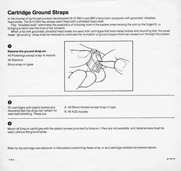
Cartridge
Ground
Straps
In
the
interest
of
continued
product
development
BTC
960’s
and
980’s
have
been
equipped
with
grounded,
shielded
head
shells.
The
B-l-C
940
has
always
been
fitted
with
a
shielded
head
shell.
This
"shielded
shell"
eliminates
the
possibility
of
inducing
hum
in
the
system
when
moving
the
arm
by
the
fingerlift,
or
bringing
a
hand
near
the
front
of
the
tonearm.
When
units
with
grounded,
shielded
head
shells
are
used
with
cartridges
that
have
metal
bodies
and
mounting
feet,
the
small
metal
"grounding"
strap
must
be
removed
to
eliminate
the
formation
of
ground
loops
which
can
cause
hum
through
the
system.
o
Remove
the
ground
strap
on:
All
Pickerings
except
snap-in
mounts
All
Stantons
Shure
snap-in
types
G
On
cartridges
with
plastic
bodies
and
A.
All
Shure
models
except
snap-in
type
mounting
feet
this
strap
can
remain
for
B
A!
|
ADC
moc
|
e
|
S
best
hum
shielding.
These
are:
o
Mount
all
Empire
cartridges
with
the
plastic
screws
provided
by
Empire;
if
they
are
not
available
and
metal
screws
must
be
used,
remove
the
ground
strap.
Refer
to
the
cartridge
manufacturer’s
instructions
concerning
these
units,
or
any
cartridge
models
not
covered
above.

THIS
UNIT
HAS
BEEN
SUPPLIED
WITH
EITHER
A
SHURE
M9IED
CARTRIDGE
OR
A
SHURE
M75ECS
CARTRIDGE,
BOTH
CONTAINING
AN
ELLIPTICAL
STYLUS.
THE
LABEL
ON
THE
CARTRIDGE
BODY
WILL
IDENTIFY
THE
CARTRIDGE
MODEL
NUMBER.
RECOMMENDED
VERTICAL
TRACKING
FORCE
(VTF)*
FOR
THE
M9IED
IS
3/4
TO
1
1/2
GRAMS.
RECOMMENDED
VERTICAL
TRACKING
FORCE
(VTF)*
FOR
THE
M75ECS
IS
1
1/2
TO
3
GRAMS.
NOTE:
SET
ANTI-SKATE
FORCE*
SAME
AS
VTF.
EXAMPLE:
IF
VTF
IS
1
1/2
GRAMS
SET
ANTI-SKATE
TO
1
1/2
GRAMS
AND
STYLUS
MODE
SELECTOR
ON
THE
960
AND
980
TO
ELLIPTICAL.
REPLACEMENT
STYLI:
FOR
THE
M9IED
USE
SHURE
N9IED
STYLUS.
FOR
THE
M75ECS
USE
SHURE
N75ECS
STYLUS.
*
PLEASE
REFER
TO
THE
OWNER’S
MANUAL
SUPPLIED
WITH
YOUR
UNIT
BEFORE
MAKING
THE
ABOVE
ADJUSTMENTS.

©o©
Multiple
Play
Manual
Turntables
Owner’s
Manual
Belt
Drive
I
Models
980
and
960
IMPORTANT
AMENDMENT
O
This
unit
has
been
fitted
(at
the
factory)
with
a
new
“Plug
In”
record
support
post.
The
diagram
below
explains
its
installation.
Installing
Plug-In
Record
Platform
Each
BTC
960
and
980
contains
a
plug-in
record
platform
supplied
in
the
styrofoam
filler.
The
record
platform
contains
a
pin
which
mates
with
a
keyway
in
the
record
platform
socket
located
in
the
left-hand,
rear
portion
of
the
unit.
Locate
the
pin
in
the
keyway
and
press
the
record
platform
firmly
down
until
it
locates
in
a
positive
manner.
When
playing
records
manually,
the
record
platform
can
be
removed
or
left
in
place.
Q
This
unit
has
also
been
fitted
with
a
new
low-mass
cartridge
head.
Disregard
all
pictures
that
may
refer
to
the
old
part.
The
mounting
instructions
remain
the
same.
BRITISH
INDUSTRIES
COMPANY,
Westbury,
N.Y.
11590
|
Division
of
Avnet,
Inc.
This manual suits for next models
1
Table of contents
Other BIC Turntable manuals


