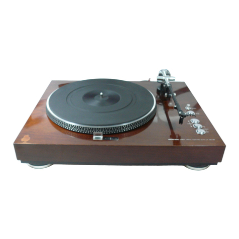
Micro Seiki BL-111 User manual

MICRO
BL-111

=
Names
of
the
parts
Dust
cover
Hinge
or
Mounting
base
Pulley
cover
Platter
Controt
panels
ia
Photo
1

=
Accessories
a
(2)
(3)
(4)
(5)
(6)
a)
(e)
(9)
(10)
(4
(12)
(13)
Dust
cover
(packed
separately)
Platter
(packed
separately)
Mounting
base
(packed
separately)
Handle
Drive
thread
(spare
provided)
Threading
ange
Hexagonal
wrench
Mounting
base
screws
MS
x
25
(6);
flat
washers
(1)
45
rpm
adapter
Strobo
mat
ower
cord
Ground
wires
(2)
Polishing
cloth

«Assembling
the
platter
Stand
the
platter
vertically,
take
out
the
accessory
drive
thread
‘©
Mounting
the
platter
and
then
attach
it
to
the
bottom
of
the
platter.
Pass
one
end
of
the
Use
the
accessory
handles
to
take
out
the
platter.
Remove
one
of
thread
loop
over
the
threading
angle.
(Photo
4)
the
handles,
tighten
the
threading
angle
together
with
the
butterfly
nut
accessory
to
the
handle
and
mount.
(Photo
3)
Threading
angle
Photo
3.

When
the
three
screws
for
anchoring
the
pulley
cover
are
loosened,
these
are
not
detached
completely
from
the
cover
but
remain
in
posi
tion
with
a
certain
amount
of
play.
Take
hold
of
these
screws
and
remove
the
pulley
cover.
Use
the
accessory
hexagonal
wrench
to
loosen
two
of
the
anchoring
screws
and
then
move
the
pulley
slide
knob
and
check
that
the
pulley
is
at
the
innermost
position.
(Photo
5)
Bulley
slide
«knob
sees
Next,
with
the
platter
as
shown
in
Photo
4,
nwunt
it
onto
the
shaft
Take
care
to
ensure
that
the
platetr
hole
is
not
bumped
against
the
shaft.
Pass
the
drive
thread
along
the
pulley
groove,
rotate
the
pulley
slide
knob
and
move
the
pulley
to
the
outside.
The
tautness
of
the
thread
should
allow
for
a
small
amount
of
slack,
which
can
be
confirmed
with
your
finger.
After
adjustment,
tighten
up
the
pulley
anchoring
screws.
(Photos
6
and
7)
After
adjustment,
detach
the
Grive
thread
from
the
end
of
the
threading
angle
and
remove
both
the
handle
and
the
angle.

After
having
attached
the
thread,
rotate
the
platter
two
or
three
revolutions
by
hand
and
check
that
the
pulley
and
platter
rotate
together
smoothly.
‘Switch
on
the
power
and
check
that
the
pulley
does
not
rotate
by
itself
when
the
platter
starts
revolving.
Now
mount
the
pulley
cover
so
that
it
falls
neatly
into
place
on
the
cabient,
taking
care
not
to
mark
the
cabinet.
Not
Take
care
to
avoid
any
adherence
of
oil
or
other
matter
on
the
parts
that
come
into
contact
with
the
thread
on
the
platter
and
pulley.
‘The
platter
is
made
of
gunmetal
and
so
crystals
may
sometimes
appear
to
be
floating
on
the
surface.
This
is
not
indicative
of
a
defect
in
the
finish.
The
platter
has
been
given
a
layer
of
clear
paint
to
prevent
dirt
from
adhering
and
so
it
should
never
be
wiped
with
any
substance
containing
alcohol
or
with
a
thinner
of
any
kind
since
this
will
cause
discoloration
and
corrosion.
=
Mounting
the
tonearm
‘*
Selecting
the
mounting
base
(A-1200
series)
Select
the
mounting
base
in
accordance
with
the
tonearm
which
you
intend
to
use.
Special
work
is
required
to
accommodate
tonearms
which
are
not
listed
below.
A
mounting
base
is
provided
with
the
BL-111
but
a
second
base
is
optional
(Special
work
is
required
to
accommodate
tonearms
which
are
included
in
the
above
list.)
=
Compatible
tonearms
A1201
MICRO/MA-505X,
S,
707X
AUDIO
CRAFT/AC-300MKII
SAEC/WE-407/23
TECHNICS/EPA-99
A-1202
SAEC/WE-30BN,
308SX
A1203
FR/FR-64,
64S,
14
DENON/DA-303,
305,
307,
399,
401
VICTOR/UA-5045
A-1205
MICRO/MA-5O5Xi1,
Sit,
808X
AUDIO
CRAFT/AC-3000MC
A-1206
‘SME/3009SII,
SII1

=
Setting
the
tonearm
‘*
Mounting
position
of
base
First,
provisionally
anchor
the
tonearm
to
the
mount
base
and
then
Mounting
the
mounting
base
with
the
index
mark
aligned
as
in
Fig.
check
the
designated
overhang.
Now
secure
the
tonearm
properly
to
2
automatically
produces
the
required
effective
length
of
the
tone-
the
mounting
base
and
then
attach
the
base
to
the
cabinet
using
the
arm
(except
in
a
few
cases)
and
the
overhang.
accessory
screws
(M5
x
25)
as
shown
in
Fig.
1
lageaiark
=
Photo
8
Mounting
base

=
Attaching
the
power
cord
and
ground
wire
~
Ground
terminat
La
Power
cord
Be
Rear
Fig.
3
The
power
cord
is
plugged
into
the
rear
panel
of
the
turntable
as
in
Fig.
3.
One
end
of
the
accessory
ground
wire
is
attached
to
the
ground
terminal
and
the
other
end
is
attached
to
the
GND
terminal
on
the
amplifier.
A
ground
terminal
is
also
provided
near
the
open-
ing
on
the
rear
panel
of
the
turntable
from
which
the
tonearm
cord
is
drawn
out.
The
ground
circuit
of
this
terminal
differs
according
to
the
tonearm
which
is
used
and
so
decide
whether
or
not
to
use
the
ground
wire
in
accordance
with
the
amount
of
noise
heard.
¢
Mounting
the
arm
rest
When
you
are
using
an
arm
rest
which
is
separate
from
the
tonearm,
the
rest
can
be
mounted
simply
without
having
to
drill
any
holes
in
the
base
if
you
provide
yourself
with
the
optional
RB-5.
RB-5
optional
arm
rest
Photo
10

Speed
selection
and
adjustments
©
Power
switch
When
this
switch
is
set
to
the
ON
position,
the
power
is
supplied
to
the
turntable
and
the
platter
starts
to
rotate.
‘*
Speed
adjustment
knob
To
adjust
the
speed,
place
the
accessory
strobo
mat
on
the
platter.
It
is
possible
to
‘nake
the
platter
rotate
up
to
6%
(semitone
pitch)
slower
or
faster
than
the
rated
rota:
tional
speed.
The
speed
is
increased
in
the
“B*
direction
and
reduced
in
the
tion.
'*
Speed
selector
switch
Every
time
this
switch
is
depressed,
the
speed
alternates
between
33
and
45
rpm.
Select
the
position
in
accordance
with
the
rated
speed
of
the
record
being
played.
When
the
power
switch
is
set
to
ON,
the
speed
is
automatically
set
to
33-1/3
rpm.

=
Mounting
and
adjusting
the
dust
cover
‘¢
Mounting
the
dust
cover
Fit
the
projection
in
the
dust
cover
bracket
into
the
cutout
in
the
turntable
bracket
and
insert
in
the
direction
of
the
arrow
to
mount.
(Photo
12)
A
free-stopping
type
of
dust
cover
is
used.
If
the
cover
does
not
close
completely
or
if
it
closes
without
stopping,
adjust
the
screw
shownsin
Photo
13.
=
Handling
precautions
and
maintenance
©
Center
shaft
wear
The
center
shaft
used
in
the
8L-111
features
2
construction
which
employs
an
oil
bath
system
to
resist
loads
and
aging.
This
is
a
semi-
permanent
system
that
is
maintenance-free
and
does
not
require
the
oil
or
bearings
to
be
replaced.
The
durability
of
the
center
shaft
is
guaranteed
and
should
any
trouble
result
under
normal
conditions
of
use,
it
will
be
replaced
by
MICRO
gratis.
Note:
Under
no
circumstances
should
the
rear
cap
of
the
center
shaft
be
removed.
Removal
of
this
cap
will
result
in
the
sealed
oil
spilling
out
and
other
trouble,
(Photo
14)
‘©
Replacement
period
for
thread
Replace
the
thread
from
time
to
time
in
order
to
maintain
its
initial
characteristics.
The
replacement
period
differs
according
to
its
use
but
once
it
becomes
too
dirty
or
appears
to
have
worn
with
friction,
it
should
be
replaced.
After
you
have used
the
spare,
obtain
the
K-5
replacement
thread
from
your
MICRO
dealer.

=
Looping
the
drive
thread
with
the
K-5
replacement
thread
(1)
Cut
the
thread
into
a
tength
of
1010
mm.
(2)
Tie the
thread
together
and
shape
it
into
the
length
shown
in
Fig.
4.
Knot
487
=
ne
——
|
i<
>|
:
thread
is
taut
|
Fig.
&
ing
the
motor
The
BL-111
motor
uses
a
special
oil
which
obviated
the
need
for
oiling
as
such.
Usage
of
any
other
type
of
oil
may
result
in
a
mal-
function
or
trouble.
(If
there
is
anything
wrong
with
the
motor,
contact
MICRO’s
Servicing
Department.)
©
Installing
the
turntable
(1)
If
the
turntable
is
instatted
near
an
amplifier
or
near
equipment
using
a
transformer,
it
will
be
affected
by
flux
and
hum
will
be
generated
as
a
result.
In
particular,
MC
cartridges
are
very
sus-
ceptible
to
the
effects
of
flux
and
so
the
turntable
should
be
installed
as
far
away
from
amplifiers
as
possible.
(Examples
of
poor
installation)
Flux
Turntable
(2)
The
reproduced
sound
will
deteriorate
if
the
turntable
is
exposed
to
vibration.
Where
possible,
install
it
on
a
sturdy
stand.
The
sound
quality
is
enahnced
if
a
glass
panel
or
marble
slab
is
used.
Avoid
installing
the
turntable
directly
infront
of
the
speakers
(where
it
will
be
exposed
to
the
sound
waves)
or
on
top
of
the
speakers.
Leave
as
large
a
clearance
with
the
wall
as
possible
when
installing
against
a
wall.
Failure
to
comply
with
these
in-
structions
may
result
in
howl
(acoustic
feedback}.
{3)
Do
not
install
the
turntable
at
an
angle
but
select
a
location
which
is
completely
horizontal.
=
Specifications
BL-111
Drive
system
Thread
drive
Rotational
speeds
33-1/3
and
45
rom
Speed
adjustment
range
+6%
Platter
31
cm
diameter,
10
kg
(gunmetal)
Moment
of
inertia
1,500
kg.cm?
Dimensions
532(W)
x
440(D)
x
230(0)
mm
Weight
36
kg
Turntable
Amplifier
ese
Power
Bd
transtormer
Fig.
5

@MICRO
SEIKI
CO.,LTD.
ron
saran
Table of contents
Other Micro Seiki Turntable manuals

Micro Seiki
Micro Seiki DD-35 User manual

Micro Seiki
Micro Seiki BL-51 User manual
Micro Seiki
Micro Seiki RS-1550 Quick start guide

Micro Seiki
Micro Seiki MB-12ST User manual

Micro Seiki
Micro Seiki DQL-120 User manual

Micro Seiki
Micro Seiki DD-33 User manual

Micro Seiki
Micro Seiki DD-40 User manual

Micro Seiki
Micro Seiki DDX-1000 User manual
Popular Turntable manuals by other brands

Crosley
Crosley T100D instruction manual

Roadstar
Roadstar HIF-1937TUMPK instruction manual

Pro-Ject Audio Systems
Pro-Ject Audio Systems RPM 6.1 SB SuperPack Instructions for use

Marshall Amplification
Marshall Amplification JTM3 3 instruction manual

LENCO
LENCO Classic Phono instruction manual

THORENS
THORENS TD402 DD user guide