Magenta TT10 User manual

ADJUSTING THE MAGENTA TT10 TURNTABLE

ADJUSTING THE MAGENTA TT10 TURNTABLE
This drawing of the stereo groove may look frightening. Yet...
...if you stick to the basic adjustments, you can enjoy the sound of analog recordings engraved in the vinyl record.
It is not at all necessary to make things complicated. Start by adjusting down force and bias, put on a record and listen. From there you can
refine the set up and adjustments if you want the highest quality in sound.
If the adjustments are not correct, even the most expensive turntable cannot fulfill its promise: the best possible sound reproduction
PREAMBLE
Why not have a turntable next to your CD Player in your set up?
The sound of records can be enlightening, records are authentic, and records can be fun.
Compared to the modern digital formats, the analogue LP record, with its signal engraved in a vinyl disc, may look poor at first glance.
However, do never forget that it is still the only medium (apart from the reel to reel tape recorder) that can contain the most complete and
most structured signal providing great dynamics, having the widest frequency band attainable, and having the most refined detail over the

ADJUSTING THE MAGENTA TT10 TURNTABLE
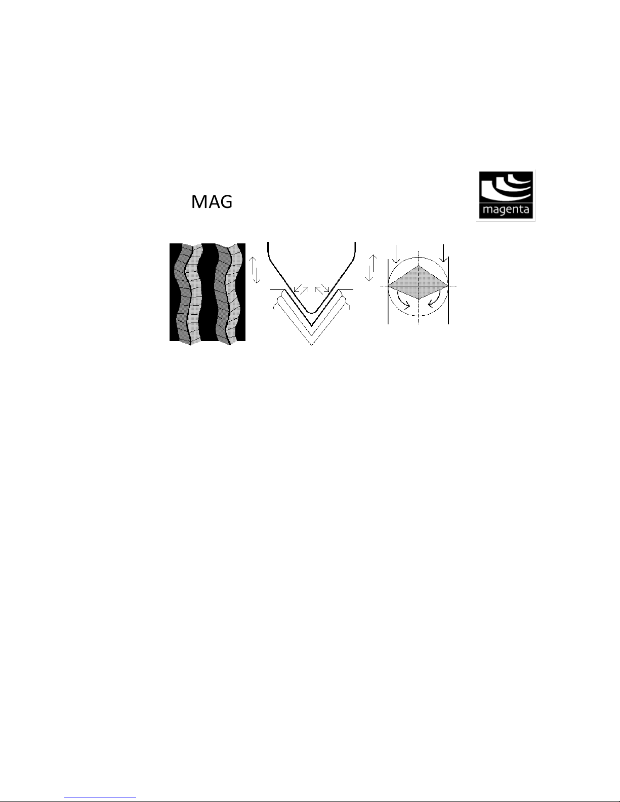
entire audio spectrum and far beyond, which no other format can deliver.
The analog LP is not restricted to 16 bits and a limited frequency band, but has 700 bits - so to speak - and the minute upper harmonics which
digital formats are missing. The simple reason is that the original LP is analogous in nature.
Or, to be more precise: analogous to nature.
PERFORMANCE VERSUS CD
If your CD outperforms your analog setup, than you do not have the right combination of components. In other words you forgot about
"system building". There are some general and specific do's and don'ts. Here are a few:
- Look for voluptuous sound, yet well controlled, look for realism.
- Look for a good, spacious mid band.
- Do not connect low efficiency loudspeaker systems to a 10 or 25 Watt tube amplifier or to a high current amplifier, but use a power amplifier
delivering current stored in a large reservoir of Micro Farads.
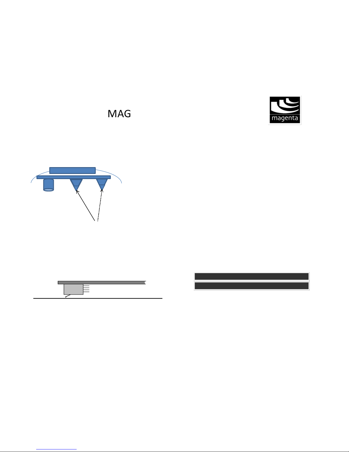
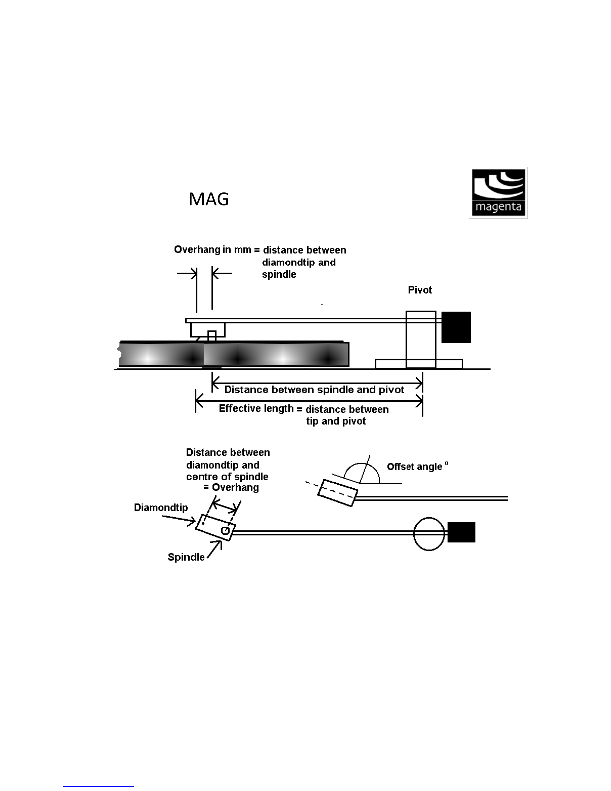
- Match cartridge and arm properly: mass (weight of the arm) in relation to compliance.
- Choose the right preamplifier to match the impedance and/or capacitance of your cartridge. Make the necessary adjustments.
- Carefully position your loudspeakers in the listening environment.
- Follow your taste and ears. Go to live concerts of classical music and jazz. There you will find that high-end does not exist in reality, only
realism.
- Do not take the PA set-up during a live concert of your favorite rock band as a reference. Because that sound is no reference at all. Many of
those experts who move the faders have a hearing problem. And soon you may have one too.
- Be well advised, but forget about the hype which surrounds so many components and is repeated by so many and far too often.
- Do not be distracted and confused by a member of a forum who says that this page gives - in his opinion - at some instances incorrect advice.
Only believe him if he points out what is incorrect. You will notice that he never does.
Even if new and more complex and high resolution digital formats are being developed and there are no appropriate players for
these formats, the recording can be engraved in a vinyl record and can be fully enjoyed. Even hundred years from now.

ADJUSTING THE MAGENTA TT10 TURNTABLE
It is of the utmost importance to adjust the turntable with arm and phono cartridge correctly.
Place the turntable on a strong cabinet, in an audio rack or on a special construction that is bolted
to the stone wall of the listening room. These supports should be level.
See to it that the turntable is perfectly level also. This is essential to minimize wow and flutter.
It is also a prerogative for the proper functioning of the phono cartridge and the arm. Only if the
turntable is level the down force and bias (side thrust) can be adjusted correctly.
LEVELING THE TURNTABLE

ADJUSTING THE MAGENTA TT10 TURNTABLE

ADJUSTING THE MAGENTA TT10 TURNTABLE
Unscrew for leveling adjustment
The TT10 To check if you have done it right just push the spindle
down with your index finger, the platter should go down and come
up always staying level. That means that the platter should not
rock or wobble. If it does you have to make new adjustments.
Adjusting is done by unscrewing the tips of the cones, the base of
the motor and the third feet is fix, so all adjustments should be
referred to the motor base.
The motor is suspended to avoid vibration transmission to the
main frame.
VERTICAL TRACKING ANGLE
INITIAL ADJUSTMENT
Check whether the arm and the head shell are parallel to the
record. Most manufacturers of cartridges take care to mount the
tip and cantilever in such a way that a Vertical Tracking Angle of
round and about 20 degrees is achieved when the arm is parallel

ADJUSTING THE MAGENTA TT10 TURNTABLE
to the record. The standard today is 20º. Vintage cartridges from
the nineteen sixties for instance have a tracking angle of 15º.
The final VTA adjustment will be done later after you have
adjusted the azimuth and down force and bias have been precisely
set.
The VTA adjustment is possible thanks to three screws in the base
of the arm.
The Margules A1.2 TT10 arm is unipivot, It is important that the
tonearm is free and can have movement to the sides up and
down.
If the base is not level properly you might have problems with the
arm elevator or restrictions the movement.
AZIMUTH ADJUSTMENT
Now check the cartridge seen from the front. It should be
perpendicular to the record. This is easily checked using a small
mirror. A precise way of measuring the azimuth is by using a test
record and a voltmeter. But this can only be done after the correct
down force and bias have been adjusted.
In Margules Arm this can be adjusted by rotating the eccentric
weight in the back of the arm.

ADJUSTING THE MAGENTA TT10 TURNTABLE
AZIMUTH REPLACEMENT STYLUS
If you have bought a replacement needle, check if the tip is really
well mounted. Check the cantilever from the front with a
magnifying glass. The cantilever should be perpendicular to the
cartridge body. The tip should be in line with the cantilever. It is a
good practice to take the small art director's magnifying glass with
you to the shop and insist that you check before you pay. A needle
tip which is out of line can not read the stereo groove. Just to be
sure.

ADJUSTING THE MAGENTA TT10 TURNTABLE
LATERAL TRACKING ERROR
While engraving the laquer disc (from which the matrix is made), the cutter head moves laterally from the outside of the lacquer to the inside. At
all instances the cutter diamond makes a 90 degree angle with the groove it has cut. This movement can be imitated by a tangential tonearm.
Most tone arms however are not tangential or parallel tracking tonearms but radial arms which move along a fixed radius. The result is that
during play the lateral angle varies. The diamond of the cartridge does not completely mimic the path originally made by the cutter head.
Use the gage supplied with the turntable and the instructions in it or in the next paragraphs you will find interesting information.
OVERHANG
When using a radial arm, there is practically at every instance a
tracking error which results in a time difference between the signals
of the left and right channel. Just a few milliseconds! Therefore it is
necessary to mount the phono cartridge in the tonearm in such a way
that this time difference is kept to an absolute minimum.
Adjusting the arm in accordance with the specified overhang (and of
course the distance between spindle and arm base as supplied, can
give the least tracking error.

ADJUSTING THE MAGENTA TT10 TURNTABLE

ADJUSTING THE MAGENTA TT10 TURNTABLE
TECHNICAL SPECIFICATIONS OF THE ARM
The alignment of cartridge and arm has to be done in accordance with the technical specifications given by the manufacturer of the pick up
arm:
* total tonearm length,
* effective length,
* overhang and
* offset angle (angle of headshell in relation to the arm tube; this angle changes in relation to the length of the arm).
Overhang is the distance between needle tip and center of the spindle. This can be seen when the cartridge is placed above the spindle (if the
arm does allow this). The effective length is the distance between pivot and diamond tip The offset angle is the angle between head shell and
arm tube
A tangential arm does not have overhang and no offset angle. The stylus should follow a straight line at a rectangular angle with the arm,
going from periphery to lable, ending at the center of the spindle. See the Rabco page.
The data of the manufacturer make it possible to determine the correct position of the arm in case you add an arm to a motor unit. Many
times one encounters a tonearm which is not built according to the findings and theories devised by various technicians, researchers and
mathematicians. One famous name in this respect is that of American engineer H. G. Baerwald. But even if the data of the arm are not
according to the findings, it is possible to find the best position of the pivot in relation to spindle and cartridge, and in relation to the groove.
No need to worry. And no need to study mathematics and trigonometry.
Much research has been done and many articles have been written about how to minimize the lateral angle to the max. I do not want to
bother you with equations. After all we have to be practical.
You may decide for yourself if you want the least distortion in the inner grooves (close to the label) were generally the most distortion is
generated. Or you may align the cartridge in such a way that zero distortion is achieved at distances of 66 mm and 120.9 mm from the spindle.
You can draw a protractor yourself. Or just print the following drawing in real size. Each square should measure 5 millimeter. If necessary

ADJUSTING THE MAGENTA TT10 TURNTABLE
adjust the size of the image so that two squares are 10 mm (=1 cm).
A member of a forum rightfully pointed out that, for a long time, I had given different measurements: 63 and 120 mm. He was right of course.
Nevertheless the deviation was not too far from the measurements given by Baerwald. It all depends on where you want the zero degree
tracking error.
Place the cartridge over the 120.9 mm
line with the needle tip precisely at the crossing. The cartridge's body should be parallel to that line.
Now lift the cartridge, move it and place it over the 66 mm mark. Again the needle tip has to be placed exactly at the point where the lines
cross (you need to turn the platter a little by hand). Then at that point the cartridge's body should again be parallel to the line when the
diamond tip is placed over the spot.
You have to adjust the arm and cartridge in such a way that at both points the configuration is exact.

ADJUSTING THE MAGENTA TT10 TURNTABLE
This template gives a general and useful indication. However, there are arms that were designed with a completely different geometry. I
recently acquired the SAEC WE 308 arm and the makers strived for the least error at the end of the record where the most distortion can
occur because in a shorter groove length the same info has to be engraved as in the outer groove.
Add to this that most of the time very loud passages are engraved, and you will understand that optimal tracking has to be near the end of
the record. But only then if the angle is not too much elevated on other spots.
The template below can tell you what the measure of lateral tracking angle in degrees is. Does not matter at what point you do measure. You
can choose the least error at whatever distance from the spindle.

ADJUSTING THE MAGENTA TT10 TURNTABLE
Shifting the cartridge makes it possible to optimize the offset angle of the tone arm and to a
certain extend the overhang and the effective length.
The template enables you to check the error
of the Lateral Tracking Angle at every position
of the arm. You can start at the small circle.
But you also can choose a different point of
departure, closer to the spindle. For instance
at (c). See to it that at your starting point the
front of the cartridge is parallel to the line
marked 0°. After that you can check at various
points and see what the error is: + or - one or
more degrees. You can save this drawing and
print it and enlarge it so that the distance
between A and B is 15 cm.
Not all arms were built with the optimum
geometry in mind, especially those which
have a fixed mount. So in certain cases it can
be necessary to shift the cartridge in the head
shell a little. This means that you are changing
the lateral tracking angle and possibly
optimizing the geometry of the arm. This can
only be done if the headshell has slots. Always
use the template pictured above to measure
the error.
If the headshell does not have slots you can
make these yourself or if you are not handy
have them made. That makes it possible to
align a cartridge in a tonearm of which you do
not have specifications. Just follow the
directions given above using the template and
find the lowest degree of error and distortion.

ADJUSTING THE MAGENTA TT10 TURNTABLE
If you do not use an
original diamond tip offered by the
manufacturer of the cartridge, you
cannot rely on the specifications of
the cartridge any longer. Specifically
if it is an old cartridge. The
replacement needles often do not
have the precisely cut and polished
tips, the tips may have slightly more
mass. In case of a moving magnet
type both the rubber and the
magnet may not be comparable with
the original quality. So it is possible
that a new manufactured tip will
alter the performance of the
cartridge: compliance and tracking
ability, band width, frequency
characteristic and dynamics. In that
case you also have to find the best
down force and side thrust which
can be completely different from the
values of the original cartridge.
DOWNFORCE - VTF
Apply the amount of down force (Vertical Tracking Force) as indicated by the
manufacturer of the cartridge. Never use a downforce that is too light. Not enough
downforce is generally more detrimental to the record groove than a downforce which
is slightly too heavy.
Each time after adjusting the down force do listen to the result. It takes some practice
and listening experience to find the optimum downforce. If the sound of a saxophone is
too light and shows an accentuation in the midband with a slight resonance, than the
downforce (in relation to the bias setting) is too light. If a clarinet gets too muddy the
downforce is too heavy. In that case also the sound image will lack in space.
In practice the downforce is hardly ever the exact value as given by the manufacturer.

ADJUSTING THE MAGENTA TT10 TURNTABLE
BIAS OR SIDE THRUST

ADJUSTING THE MAGENTA TT10 TURNTABLE
READING THE HORIZONTAL
AND VERTICAL SIGNAL
When Edison designed his Phonograph Cylinder, he engraved the sound
in a vertical movement: the needle went up and down, or "hill and dale"
as it is called.
Emil Berliner from Germany designed the gramophone record and he
engraved the signal in a lateral or horizontal movement.
The combination of these two "systems" made the stereo record possible.
In order to give both the left and right channels the same technical
parameters, this combination of lateral and vertical engraving was turned
45 degrees. The contact of the diamond tip to both walls of the groove
should be the same, despite the fact that it changes while playing a
record.

ADJUSTING THE MAGENTA TT10 TURNTABLE
BIAS COMPENSATION
When a disc is spinning and you place a small object on it, the object will
be swept off the disc by the centrifugal force (CF). You can try this
yourself by placing a small object on the platter.
When a record is turning, and the needle tip is held in a spiral groove at
one end and the tonearm is fixed on the other end, a force will be
exercised on the arm and cartridge. This force has now become
a centripetal force(CP) which will move the cartridge towards the spindle,
all caused by the fixation at the pivot of the arm. Now the arm can only
move in a radial way as it is held in position by the pivot.
The result is that there will be an increased pressure on the groove wall
which contains the sound of the left channel. In order to neutralize this
force, and to give both groove walls equal pressure, it is necessary to
compensate this effect by applying a counteracting force at the other end
of the arm, passed the pivot (BA). The force to be applied is called side
thrust compensation or bias compensation. It is done by means of a
pending weight or a magnetic force.
A linear / parallel tracking arm does not need this correction
because the pivot continuously changes its position.
When adjusting the bias or side thrust (BA) precisely, use a test record
with a groove-less section. The right amount of side thrust compensation
(in relation to the downforce) will keep the cartridge from moving either
towards the spindle or towards the periphery of the LP record.
You may also play the tracks of a test record containing heavily
modulated signals for left and right, and listen carefully at what level of
bias compensation + down force the distortion is the least, or even
completely absent.

ADJUSTING THE MAGENTA TT10 TURNTABLE
If you are a perfectionist, you may connect an oscilloscope alternately to
the left and right outputs of your preamplifier (or the Record Out
sockets), and check the bias adjustment by playing the test with separate
left and right channel signals, in various modulations, starting at 50 um.
The use of a Clamp makes it possible to choose a more precise downforce
and bias as the use of these gadgets do reduce distortion already to a
great extend. This will result in a better adjustment and a much better
signal.

ADJUSTING THE MAGENTA TT10 TURNTABLE
Other manuals for TT10
1
Table of contents
Other Magenta Turntable manuals