Bicker DC300WS User manual
English
Bicker Elektronik GmbH
Ludwig-Auer-Straße 23 |86609 Donauwörth·Germany
USER MANUALUSER MANUAL
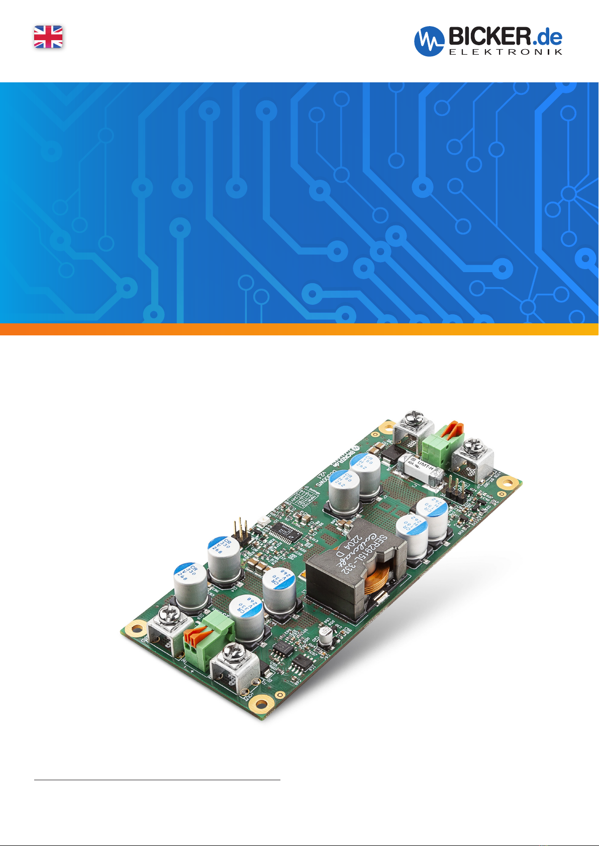
DC300WS
DC /DC 300W POWER SUPPLY

DC300WS
Revision 1-0 2
Revision Directory
Legend of used symbols
Symbol Description
Attention! Important hazard warning.
Do not dispose of in the domestic waste.
Warning of electrical voltage.
Date Change
16.05.2023
Revision 0-4
Initial version
19.06.2023
Revision 1-0
Release version

DC300WS
Revision 1-0 3
Input voltage 6V–36 V
Input current <40A
Output voltages 12V, 19V, 24V – adjustable via jumper
Max. output current 12V/25A
19 V/15.8V
24 V/12.5A
Max. output power 300W at all adjustable output voltages
Capacitive load 4700 µF
Protection Input:
· Active reverse polarity protection
· UVLO (under voltage lockout)
· UVP (over voltage lockout)
Output:
· OVP (overvoltage protection)
· OCP (active overcurrent and short circuit protection)
Derating See chapter D2
Ambient temperature Operating Storage/Transport
-20…+70°C -20…+70°C
Operating altitude ≤5000 m
Max. permitted humidity ≤95% (at +25°C, no dew)
Dimensions W/ H / D 132 x 17 x 56 mm
Weight ~115 g
Technical Data
A Brief specification
DC300WS
Powerful DC/DC converter with 300 W
output power from 6–36 V
Ultra wide input range 6…36 V DC
Adjustable ourput voltage
+12 V, +19 V or +24 V DC
Very compact design
Full power in extended temperature range
-20...+60°C
High efficiency up to 98 %
More than 10 years capacitor lifetime
Optional compensation of the output voltage
via sense lines
Optional Remote On/Off

DC300WS
Revision 1-0 4
Legend of used symbols...................................................................................................................................................2
Revision Directory..................................................................................................................................................................2
A Brief specification.................................................................................................. 3
B Introduction and description ............................................................................... 5
B1 Description of the product and its functions ............................................................................................5
B2 Intended use .................................................................................................................................................................5
C Safety instructions ................................................................................................ 6
D Technical Data ....................................................................................................... 7
D1 General Technical Data............................................................................................................................................7
D2 Derating.......................................................................................................................................................................... 12
D3 Drawing........................................................................................................................................................................... 13
E Name / Address / Support E-Mail / Phone number of the manufacturer ....... 13
F General Data ........................................................................................................ 14
F1 Assembly and installation advice...................................................................................................................14
F2 Installation and cooling........................................................................................................................................ 14
F3 Description of connectors................................................................................................................................... 15
Output voltage configuration (J3) ................................................................................................................. 15
Remote Sense (J4)....................................................................................................................................................16
Remote ON/OFF (J5/J6)........................................................................................................................................ 16
F4 Initial operation..........................................................................................................................................................17
F5 Scope of delivery....................................................................................................................................................... 17
F6 Accessories.................................................................................................................................................................... 17
F7 Reverse polarity / Overcurrent / Short circuit ........................................................................................17
F8 Maintenance................................................................................................................................................................ 18
F9 Disposal...........................................................................................................................................................................18
F10 Disclaimer ......................................................................................................................................................................18

DC300WS
Revision 1-0 5
B Introduction and description
Read carefully before initial operation!
This manual shall help the user to get familiar with the product and its components and features. It shall pro-
vide information as accurately and completely as possible.
The manual as well as all documents has to be read and followed strictly before installation. Otherwise warranty
and guarantee can be cancelled partly or completely. Any liability on the part of Bicker Elektronik is excluded
for possible existing errors as well as non-compliance with the instructions for use and installation.
B1 Description of the product and its functions
The DC300WS is a powerful DC/DC converter with an output power of up to 300 W and a wide input voltage
range of 6 - 36 V. From an input voltage of 11V, full power can be drawn over the entire ambient temperature
range from -20 to +70°C without derating. Via the jumper (J3) the user can set the output voltage to 12 V,
19 V or 24 V before operation. A green status LED indicates that the converter is ready for operation.
The DC300WS also has the option of controlled activation of the device using active low logic (remote on/off)
via the input-side, separate spring contact connection (J6). Jumper (J5) must be set to use this functionality as
described in later chapters.
Sense lines can optionally be connected via the spring contact connection (J4) on the output side in order to
compensate the voltage drop at the output with long lines and high currents.
The DC300WS has several protections to safe the device from errors and defects. These include reverse pola-
rity protection on the input side, input undervoltage blocking, input overvoltage protection, overtemperature
protection and output-side overvoltage and short-circuit protection.
B2 Intended use
The device is a power supply for subsequent devices. It is designed for use in a suitable metal housing. When
installing, make sure that the DC300WS is connected to the housing via the supplied gap pad in order to ensu-
re cooling of the components underneath.
The ambient temperature specified in the technical details is the air temperature directly at the components
and must not fall below (minimum value) or exceed (maximum value).
The power supply is primarily designed for professional use in areas such as industrial control, communications
and instrumentation. It must not be used in devices or systems in which a malfunction could lead to serious
injuries or endanger human life.
The device is not designed to charge energy storage devices such as batteries, EDLC or lithium batteries. When
used as a charger, it can cause fire or endanger life and limb!
The device must be protected from being touched during operation because, depending on the power, the
temperatures can get too high and cause burns.
DC300WS
Revision 1-0 6
C Safety instructions
WARNING!
Disregarding of following issues can result in electric shock, fire, serious injury or death.
1. Care must be taken to ensure proper and professional wiring.
2. The device pack must not be exposed to fire and temperatures outside the specification.
3. The device must not be immersed in water or exposed to splash water.
4. The device must not be operated in a humid environment or in an environment where dew and
condensation are to be expected.
5. The device must not be opened, overheated or otherwise soldered/welded.
6. Changes or attempts to repair the device are to be omitted.
7. Effects of foreign objects on the device must be avoided (e.g. metal parts).
8. Do not put obviously damaged devices into operation (e.g. dents, burn marks, rough contamination).
9. Keep ventilation openings clear.
10. Device must not be dropped.
11. All parts of the device and accessories must not be eaten or swallowed.
12. A current limited source is to be used.
13. During operation, the circuit board, the housing and any exposed connections must not be touched.
Touching the circuit board, the housing or the connection terminals can cause burns, especially at
very high power levels.
14. The device is not suitable for direct charging of energy storage devices
1. Improper use as well as opening and disassembling of the device will void the warranty.
2. The device may only be used as intended.
3. The national accident prevention and safety regulations must be observed.
4. The assembly of the device and the electrical installation have to be state of the art.
5. The electrical, thermal and mechanical limit values have to be observed.
6. The DC300WS wiring specifications - as described in this manual - have to be followed.
ATTENTION!

DC300WS
Revision 1-0 7
D Technical Data
D1 General Technical Data
INPUT DATA
Unless otherwise stated, all specifications apply to +25°C ambient temperature,
6–36 V DC input voltage and nominal output current (IN).
Input voltage DC
Input voltage range 6–36 VDC
Electric strength max. 39 V
Approximate current consumption
@ 300 W output power
UIN = 12V
UIN = 19V
UIN = 24V
UIN = 36V
~27A
~17A
~13.5A
~9.0A
Efficiency up to 98%
Internal input fuse 40 A (SMD)
Standby consumption <1W
PSON setting (J5) J5 1-2: PSON (J6) active; PSON (J6) short-circuit = on
J5 2-3: PSON (J6) inactive, permanent on
Switch-on time ≤1.6 sec
Protection under voltage: 5V
over voltage: 39V
active reverse polarity
Insulation voltage No separation between input and output
DC300WS
Revision 1-0 8
OUTPUT DATA
Unless otherwise stated, all specifications apply to +25°C ambient temperature,
6–36 V DC input voltage and nominal output current (IN).
Output voltage 12V, 19V, 24 V– adjustable via Jumper
Output voltage tolerance +5% / –1.5%
Capacitive load 4700 µF
Maximum output current
UOUT = 12V
UOUT = 19V
UOUT = 24V
25 A
15.8 A
12.5A
Ripple & Noise max. 100 mVp-p
Output power 300W
Protection Short circuit
Over current >41A
Over voltage >28V
Derating See chapter D2
CONNECTION DATA INPUT (J7, J8) / OUTPUT (J1, J2)
Connection method Screwterminal M4
Conductor cross-section solid not provided
Conductor cross-section flexible 12 … 14 AWG / 3.3…2.08 mm²
Ring or fork cable lug
Conductor cross-section with ferrule not provided
Stripping length n.a.
Tightening torque 1.1Nm
CONNECTION DATA PSON (J6) / SENSE (J4)
Connection method Spring contact clamp (screwless)
Conductor cross-section solid 20 … 26 AWG / 0.5…0.12 mm²
Conductor cross-section flexible 20 … 26 AWG / 0.5…0.12 mm²
Conductor cross-section with ferrule not provided
Stripping length 9…10 mm
Tightening torque n.a.
DC300WS
Revision 1-0 9
GENERAL DATA
Flammability class according to UL 94
(housing / terminal blocks)
Yes
Weight ~115 g
UPS connection in parallel No
UPS connection in series No
HOUSING
Degree of protection n.a.
Protection class n.a.
Mounting type n.a.
Housing version n.a.
Dimension W / H / D n.a.
ENVIRONMENTAL CONDITIONS
Ambient temperature (operation) -20… +70°C
Ambient temperature (start up without load) -30°C
Ambient temperature
(storage / transport)
-20… +70°C
Max. permitted humidity Operating: 10…90% RH, non-condensing
Storage: 10…95% RH, non-condensing
Operating altitude ≤5000 m
Climate class 3k3 (EN 60721)
Degree of pollution 2
Overvoltage category
EN 61010-1
EN 61010-2-201
I
I
Indoor / Outdoor use Yes / No
STANDARDS
Safety extra-low voltage IEC 61010-1 (SELV)
IEC 61010-2-201
APPROVALS
UL n.a.
CSA n.a.
CB Scheme n.a.
DC300WS
Revision 1-0 10
INTERFERENCE IMMUNITY ACCORDING TO EN 61000 (INDUSTRY)
Basic standard CE Fulfilled requirements according to EN 61000 (CE)
(Interference immunity of industrial environment)
Electrostatic discharge
EN 61000-4-2
Contact discharge
Air discharge
Comment
4 kV
8 kV
Criterion A
Fast transients (Burst)
EN 61000-4-4
Test voltage
Comment
2 kV
Criterion A
Surge voltage load (Surge)
EN 61000-4-5
Test voltage L–N
Test voltage L–PE, N–PE
Comment
2kV
4kV
Criterion A
LEGEND
Criterion A Normal operating behaviour within the defined limits.
Criterion B Temporary impairment of the operating behaviour, that is
corrected by the device itself.
EMISSION ACCORDING TO EN 55016-2-3 (DOMESTIC)
Basic standard CE Fulfilled requirements according to EN 55016-2-3 (CE)
(Domestic)
Conducted emission from the power port
EN 55016-2-3
Frequency range
Comment
The power supply has no built-in filter components. It is the
user‘s responsibility to take appropriate measures and to eli-
minate interference in their entire system in order to comply
with the legally specified limit values.
Electric field radiated emission
EN 55016-2-3
Frequency range
Comment
The power supply has no built-in filter components. It is the
user‘s responsibility to take appropriate measures and to eli-
minate interference in their entire system in order to comply
with the legally specified limit values.
DC300WS
Revision 1-0 11
D2 Derating
ϭϬϬ
ϭϮϱ
ϭϱϬ
ϭϳϱ
ϮϬϬ
ϮϮϱ
ϮϱϬ
Ϯϳϱ
ϯϬϬ
ϯϮϱ
ͲϮϬ ͲϭϬ Ϭ ϭϬ ϮϬ ϯϬ ϰϬ ϱϬ ϲϬ ϳϬ
KƵƚƉƵƚWŽǁĞƌ;tͿ
ŵďŝĞŶƚdĞŵƉĞƌĂƚƵƌĞ;ΣͿ ϭ
ϭϮsŽƵƚ
sŝŶϭϯͲϯϲ
sŝŶϭϭͲϭϮ
sŝŶϭϬ
sŝŶϲ
12 VOUT
ϭϬϬ
ϭϮϱ
ϭϱϬ
ϭϳϱ
ϮϬϬ
ϮϮϱ
ϮϱϬ
Ϯϳϱ
ϯϬϬ
ϯϮϱ
ͲϮϬ ͲϭϬ Ϭ ϭϬ ϮϬ ϯϬ ϰϬ ϱϬ ϲϬ ϳϬ
KƵƚƉƵƚWŽǁĞƌ;tͿ
ŵďŝĞŶƚdĞŵƉĞƌĂƚƵƌĞ;ΣͿ ϭ
ϭϵsŽƵƚ
sŝŶϭϮͲϯϲ
sŝŶϭϭ
sŝŶϭϬ
sŝŶϲ
19 VOUT
1 : Temperature directly at the components

DC300WS
Revision 1-0 12
Ϭ
ϱϬ
ϭϬϬ
ϭϱϬ
ϮϬϬ
ϮϱϬ
ϯϬϬ
ϯϱϬ
ͲϮϬ ͲϭϬ Ϭ ϭϬ ϮϬ ϯϬ ϰϬ ϱϬ ϲϬ ϳϬ
KƵƚƉƵƚWŽǁĞƌ;tͿ
ŵďŝĞŶƚdĞŵƉĞƌĂƚƵƌĞ;ΣͿ ϭ
ϮϰsŽƵƚ
sŝŶϭϮͲϯϲ
sŝŶϭϭ
sŝŶϭϬ
sŝŶϲ
24 VOUT
1 : Temperature directly at the components
DC300WS
Revision 1-0 13
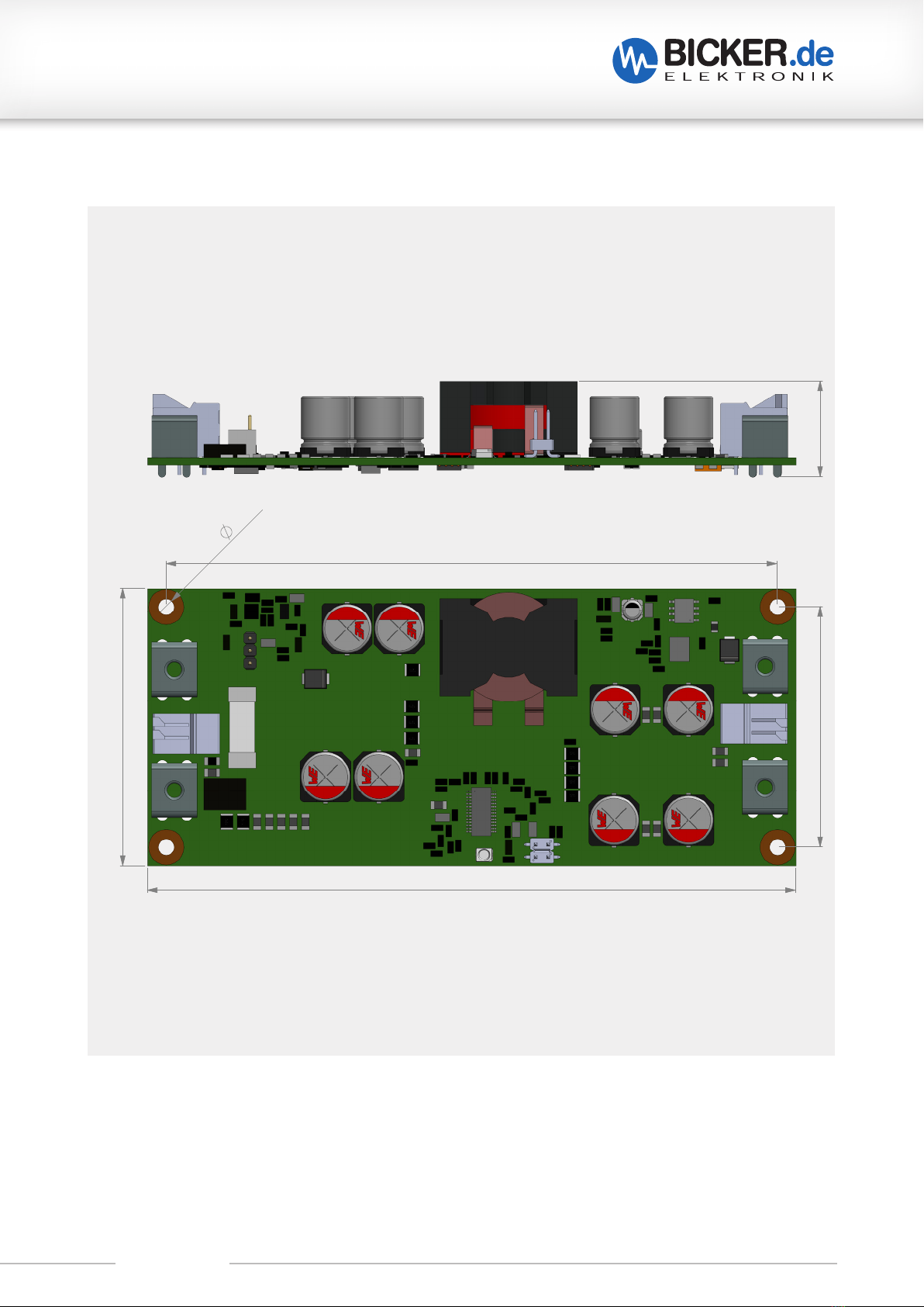
D3 Drawing
131,7mm
56,3mm
124,1mm
48,8mm
4x 3,20
20,0mm
E Name / Address / Support E-Mail / Phone number of the manufacturer
Bicker Elektronik GmbH · Ludwig-Auer-Straße 23 · 86609 Donauwörth · Germany
Unless otherwise stated,
Tolerance according to:
DIN ISO 2768 T1 - m
DIN ISO 2768 T2 - K
DC300WS
Revision 1-0 14
F General Data
F1 Assembly and installation advice
Installation and operation of this device is only allowed to be executed by a qualified
electrician! The application has to be separated from any power during the mounting process.
Wires have to be connected safely and must not have contact with sharp edges. Pay attention
to correct polarity! Before commissioning, check all the connections for correctness!
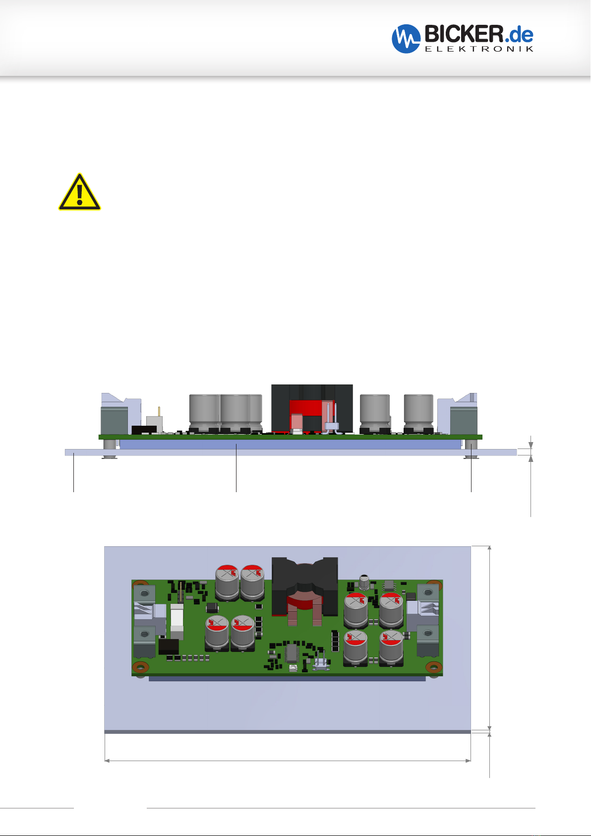
F2 Installation and cooling
Using the provided gap pad the DC300WS has to be mounted in a metal case via the bottomside of the
board. In order to cool the power supply, a heat-absorbing surface of at least 170 cm² and a minimum mate-
rial thickness of 1.5 mm are required (drawing below). During operation, it must be ensured that the ambient
temperature directly at the components is within the permitted range. For installation in a case, spacers with a
height of 3mm have to be used at the mounting holes to avoid bending and thus damaging the power supply.
1,5 mm
155,0mm
110,0mm
1,5mm
metal chassis bottom Gap Pad 3mm spacer 3mm

DC300WS
Revision 1-0 15
F3 Description of connectors
TYPE FUNCTION
J1 VDC output Plus (+)
J2 VDC output Minus (–)
J3 Configuration output voltage
J4 Output sense connection
J5 Remote On/Off configuration
J6 Remote On/Off connection
J7 VDC input Plus (+)
J8 VDC input Minus (–)
UPSI-
2406D
16
Revision 1-
1
F3
Anschlussbeschreibung
Kennung
Funktion
J1
VDC Ausgang Plus (+)
J2
VDC Ausgang Minus (-)
J3
Konfiguration Ausgangsspannung
J4
Ausgang-Sense Anschluss
J5
Remote Ein / Aus Konfiguration
J6
Remote Ein / Aus Anschluss
J7
VDC Eingang Plus (+)
J8
VDC Eingang Minus (-)
Konfiguration Ausgangsspannung (J3)
Zum Konfigurieren der Ausgangsspannung werden die Pins mittels eines Jumpers gemäß untere Tabelle
eingestellt.
Die Einstellung darf nur bei abgeschalteter Spannungsversorgung erfolgen!
Ausgangsspannung
Pin Konfiguration
Bild
12 Volt
keine
19 Volt
Pin 1-2
24 Volt
Pin 1-2
Pin 3-4
J8
J1
J7
J6
F1
J2
J5
J3
1
1
2
+
Out
-
Out
In -
In +
J4
Sense
+
Sense
-
1
Remote On/Off (+)
GND (-)
OUTPUT VOLTAGE CONFIGURATION (J3)
To configure the output voltage, the pins are set using a jumper as shown in the table below
.
The setting may only be made when the power supply is switched off!
OUTPUT VOLTAGE PIN CONFIGURATION PICTURE
12 Volt no
19 Volt Pin 1-2
24 Volt Pin 1-2
Pin 3-4
UPSI-
2406D
16
Revision 1-
1
F3
Anschlussbeschreibung
Kennung
Funktion
J1
VDC Ausgang Plus (+)
J2
VDC Ausgang Minus (-)
J3
Konfiguration Ausgangsspannung
J4
Ausgang-Sense Anschluss
J5
Remote Ein / Aus Konfiguration
J6
Remote Ein / Aus Anschluss
J7
VDC Eingang Plus (+)
J8
VDC Eingang Minus (-)
Konfiguration Ausgangsspannung (J3)
Zum Konfigurieren der Ausgangsspannung werden die Pins mittels eines Jumpers gemäß untere Tabelle
eingestellt.
Die Einstellung darf nur bei abgeschalteter Spannungsversorgung erfolgen!
Ausgangsspannung
Pin Konfiguration
Bild
12 Volt
keine
19 Volt
Pin 1-2
24 Volt
Pin 1-2
Pin 3-4
J8
J1
J7
J6
F1
J2
J5
J3
1
1
2
+ Out
- Out
In -
In +
J4
Sense +
Sense -
1
Remote On/Off (+)
GND (-)
DC300WS
Revision 1-0 16
The J6 connection has neither reverse polarity nor overvoltage protection and improper use can damage the
entire device.
Pay attention to the stripping length of the connecting strand of 9…10 mm.
The wired spring clip connector J4 must be checked for tightness by a gentle pull test prior to use.
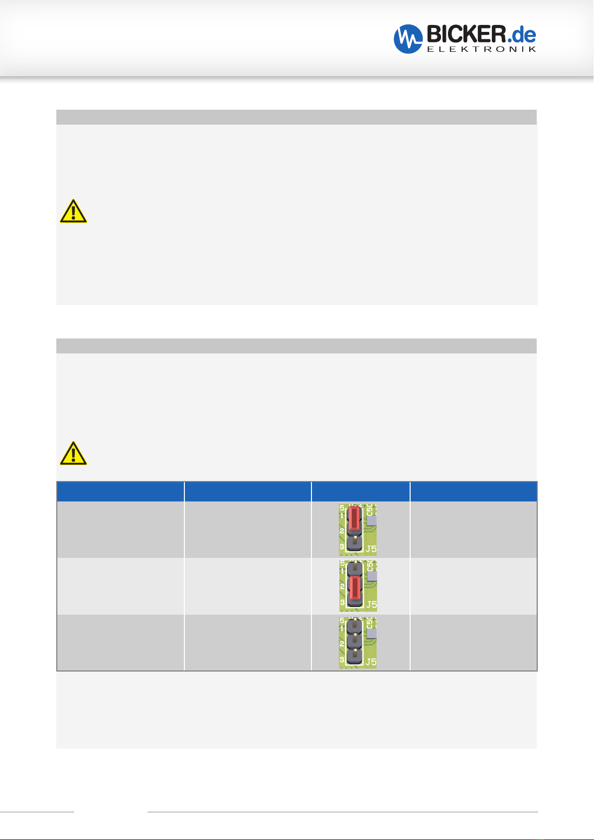
REMOTE ON/OFF (J5/J6)
Remote activation can be activated via the jumper (J5) by bridging Pin 1 and Pin 2. When the configuration is
activated, the power supply must be switched on via the connector (J6). This is done either by permanently
shorting the two connections of J6, or by setting J6 pin 1 to ground (–). If pins 2 and 3 of (J5) are bridged or
not bridged at all, the power supply switches on as soon as an input voltage is present.
J5 CONFIGURATION REMOTE ACTIVATED PICTURE FUNCTIONALITY
Pin 1 – Pin 2 Yes Output active: J6 Remote
On/Off to ground or both
pins shorted
Pin 3 – Pin 4 No Output voltage active
when input voltage
is present
non No Output voltage active
when input voltage
is present
UPSI-
2406D
17
Revision 1-
1
Remote On / Off (J5 / J6)
Die Remoteaktivierung kann über den Jumper (J5) durch Brücken von Pin 1 und Pin 2 aktiviert werden. Wenn die
Konfiguration aktiviert ist, muss das Netzteil über den Anschluss (J6) angeschaltet werden. Dies erfolgt entweder
über das dauerhafte Kurzschließen der beiden Anschlüsse von J6 oder über J6-Pin 1 auf Masse (-). Sind bei (J5)
die Pins 2 und Pin 3 gebrückt oder überhaupt nicht gebrückt, schaltet sich das Netzteil an, sobald eine
Eingangsspannung anliegt.
Der Anschluss der Leitungen und Jumper muss bei abgeschalteter Spannungsversorgung erfolgen!
Es darf keine aktive Spannung an den Pins von J6 angeschlossen werden!
J5 Konfiguration
Remote aktiviert
Bild
Funktionalität
Pin 1 –Pin 2
Ja
Ausgang aktiv:
J6 Remote On / Off auf
Masse oder beide Pins
kurzgeschlossen
Pin 3 –Pin 4
Nein
Ausgangsspannung bei
anliegender
Eingangsspannung
aktiv
keine
Nein
Ausgangsspannung bei
anliegender
Eingangsspannung
aktiv
Der Anschluss J6 besitzt weder einen Verpol- noch einen Überspannungsschutz. Es kann bei nicht-
bestimmungsgemäßem Gebrauch zur Beschädigung des Gesamtgerätes kommen.
Es ist auf die Abisolierlänge der Anschlusslitze von 9..10mm zu achten. Der verkabelte Federklemmenanschluss J4
muss vor Gebrauch durch einen sanften Zugtest auf festen Sitz geprüft werden.
Remote Sense (J4)
Über den Anschluss (J4) können Messleitungen an die Eingangspunkte des zu betreibenden Gerät verbunden
werden. Dadurch werden Spannungsabfälle bei zu langen Leitungen, die durch hohe Ströme verursacht werden,
automatisch ausgeglichen.
Der Anschluss der Leitungen muss bei abgeschalteter Spannungsversorgung erfolgen!
Es ist darauf zu achten, dass die Polung stimmt und es müssen beide Messleitungen (Sense + und
Sense -) angeschlossen werden!
Der Anschluss J4 besitzt weder einen Verpol- noch Kurzschlussschutz und es kann bei nicht
bestimmungsgemäßem Gebrauch zur Beschädigung des Gesamtgerätes kommen.
Es ist auf die Abisolierlänge der Anschlusslitze von 9..10mm zu achten. Der verkabelte Federklemmenanschluss J4
muss vor Gebrauch durch einen sanften Zugtest auf festen Sitz geprüft werden.
The lines and jumpers have to be connected when the power supply is switched off! No
active voltage may be connected to the J6 pins!
REMOTE SENSE (J4)
Via the connection (J4) measuring lines can be connected to the input points of the device to be operated.
This automatically compensates for voltage drops caused by high currents, when lines are too long.
The J4 connection has neither reverse polarity nor short-circuit protection and improper use can damage the
entire device. Pay attention to the stripping length of the connecting strand of 9…10 mm.
The wired spring clip connector J4 must be checked for tightness by a gentle pull test prior to use.
The connection of the lines must be done when power supplies are switched off!
It must be ensured that the polarity is correct and both measuring lines (Sense + and
Sense –) have to be connected!

DC300WS
Revision 1-0 17
F4 Initial operation
The correct installation of the power supply has to be ensured. Alle cables at the connectors have to be
checked for proper contact, seating and polarity. The desired output voltage is to be set via the jumpers as in
„Output voltage configuration“.
After that, start takes place by applying the supply voltage: From a voltage of 5V at the input terminals,
the power supply provides the set output voltage.
It is important to ensure that the source supplies enough current to guarantee the required power at the out-
put. The formula
PIN = POUT MAX
x 1.25
can be used as a guideline for dimensioning an input voltage supply.
F5 Scope of delivery
SCOPE OF DELIVERY
QUANTITY DESCRIPTION
1x device DC300WS
1x Gap-Pad
3x 2.54mm Jumper mating connector
4x 3mm spacer round
F6 Accessory
PSZ-1111: aluminium U chassis with cover
F7 Reverse polarity / Overcurrent / Short circuit
Reverse polarity:
The device has active reverse polarity protection at the input if the input terminal is connected with reverse
polarity while the device is still switched off (e.g. during commissioning).
Overcurrent:
If the load current at the output is too high, the device switches it off. For maximally allowed current values
and peak current values refer to chapter D „Technical Data”. A restart attempt occurs every 1ms (non-lacht). If
the power supply is in this state, the LED switches off.

DC300WS
Revision 1-0 18
Short circuit:
In the event of a short-circuit at the output of the power supply, the output is immediately disconnec-
ted (<5ms). A restart attempt occurs every 1ms in normal mode (non-latch). The impact of a short-
circuit to the device depends on length and diameter (impedance) of the output wiring. In case of a short-circuit
directly at the plugs a damage of the device can occur.
If the power supply is in this state, the LED switches off.
F8 Maintenance
The UPS contains no serviceable parts. In case of a malfunction the upstream power source has to be discon-
nected and cables have to be removed. Use a dry cloth for cleaning!
F9 Disposal
Electric and electronic devices must not be disposed with domestic waste!
Please consider to each country’s own regulation about recycling and dispo-
sal of used batteries at the end of their lifetime or resending to any recycling
organization.
F10 Disclaimer
We, the Bicker Elektronik GmbH, have checked the contents of this document for compliance with the hard-
ware and software described. Nevertheless, deviations can not be ruled out, so we assume no liability for the
complete agreement. The information in this publication is checked regularly, necessary corrections are inclu-
ded in the updated versions.
Suggestions for improvement as well as tips and criticism are always welcome.

Note: Subject to errors and technical modifications!
Windows® is a registered trademark of the Microsoft Corp.
Status as at: 19.06.2023 – Revision 1-0
Bicker Elektronik GmbH
Ludwig-Auer-Straße 23
86609 Donauwörth·Germany
Tel. +49 (0) 906 70595-0
Fax +49 (0) 906 70595-55
E-Mail [email protected]
www.bicker.de
Other Bicker Power Supply manuals


