ELC ALR3203 User manual
USER MANUAL
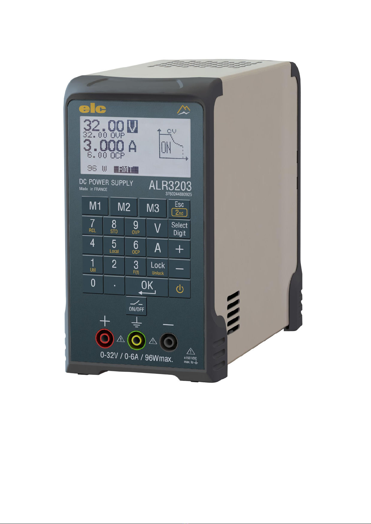
ALR3203 0 –32 V ; 0 –6 A ; 96W max
DC STABILIZED PROGRAMMABLE POWER SUPPLY

4000 4 362-03-21 2 ENGLISH
SYNOPSIS
1PREFACE.............................................................................................................................. 3
2DESCRIPTION ...................................................................................................................... 3
2.1 PRESENTATION ................................................................................................................... 3
2.2 FUNCTIONAL DESCRIPTION OF THE UNIT ......................................................................... 3
2.3 SAFETY INSTRUCTIONS...................................................................................................... 4
2.4 SAFETY TERMS AND SYMBOLS ..........................................................................................4
2.5 PACKAGING AND REPACKAGING ....................................................................................... 4
3OPERATING.......................................................................................................................... 5
3.1 TECHNICAL FEATURES ....................................................................................................... 5
4OVERVIEW ........................................................................................................................... 8
4.1 FRONT PANEL ...................................................................................................................... 8
4.2 REAR PANEL ........................................................................................................................9
5SHORT DESCRIPTION OF THE FRONT PANEL ................................................................ 10
5.1 DISPLAY.............................................................................................................................. 10
5.2 KEYPAD AND SHIFT ........................................................................................................... 10
5.3 KEYS CONTROL ................................................................................................................. 10
5.4 ON/OFF : GENERAL &STANDBY........................................................................................ 10
5.5 KEYS SETTING ................................................................................................................... 10
5.6 SOUND SIGNAL.................................................................................................................. 10
5.7 SAFETY SOCKETS CHANNEL............................................................................................ 10
5.8 EARTH FUNCTIONNAL SOCKETS ..................................................................................... 10
6DESCRIPTION OF CONTROL COMMANDS....................................................................... 11
6.1 PARAMETERS SETTING .................................................................................................... 11
6.2 MEMORIES ......................................................................................................................... 13
6.3 CONTROL UTILITIES .......................................................................................................... 14
6.4 PROGRAMMED FUNCTIONS.............................................................................................. 14
6.5 OTHER FUNCTIONS ........................................................................................................... 15
7PC CONTROL ..................................................................................................................... 16
8MAINTENANCE................................................................................................................... 17
8.1 TROUBLESHOOTING ......................................................................................................... 17
8.2 ERROR MESSAGE.............................................................................................................. 17
9AFTER SALE SERVICE ...................................................................................................... 17
10 DECLARATION OF CONFORMITY..................................................................................... 18
APPENDIX A–OPERATING CODES ............................................................................................... 19
APPENDIX B–USB CONNECTION .................................................................................................. 22
APPENDIX C–SEQUENCER .......................................................................................................... 22

4000 4 362-03-21 3 ENGLISH
1 PREFACE
Manufacturer : ELC 59 avenue des Romains 74000 ANNECY - FRANCE
Phone : +33 (0)4 50 57 30 46 Fax : +33 (0)4 50 57 45 19
Item : DC STABILIZED PROGRAMMABLE POWER SUPPLY
Brand : elc
Type : ALR3203
2 DESCRIPTION
2.1 PRESENTATION
You just bought a DUAL DC STABILIZED PROGRAMMABLE POWER SUPPLY type elc ALR3203. We
thank you and congratulate you for your good choice.
elc's company is a specialist manufacturer proposes a wide range of POWER SUPPLIES and many
other electronic test instruments : FUNCTION GENERATORS, DECADE BOXES, DIGITAL PANEL
METERS...
This item has been conceived according to the European standard EN61010-1 and supplied in good
condition. This electrical instrument is intended to professionals, industrials and school users. This
instructions manual contains information and notes, which must be respected by the purchaser, in order
to ensure a safe working and to maintain the instrument in good condition.
2.2 FUNCTIONAL DESCRIPTION OF THE UNIT
This item is used in laboratories. It is designed with :
a large graphic display, a touch keypad, a compact vertical box with an handle and a cord storage
integrated in the rear panel. This item will give you satisfaction by offering many possibilities.
Fully programmable, this power supply can be controlled in several ways :
- via the front panel using the keypad
- via the isolated USB interface
This DC power supply is regulated in voltage of 0 to 32V and current of 0 to 6A 96W max.
Several programmable functions U and I are accessible directly from the keypad and you will make
positive or negative ramp, up or down time, or a square, or arbitrary wave.
The output can be turned “ON” or “OFF” (by key or input signal) and there is a sleep mode by a
“standby” touch.
All parameters are displayed on the graphic display.
4000 4 362-03-21 4 ENGLISH
2.3 SAFETY INSTRUCTIONS
Before any operation, read the following safety precautions to avoid injury and
prevent damage to this product or another connected.
oTo avoid all potential hazards, use this product only in the specified
limits.
oDo not use the device without its cover. Do not use the item with its
housing or any panels removed.
oAny intervention inside the casing, and particularly the fuses replacement,
must imperatively be effected by a skilled staff.
oThe instrument must be used according to the instructions of this manual.
oUse it in a well ventilated area. The air inlets and the fan outlet must be
widely free, do not block them.
oDo not use in wet conditions. Do not use in wet environment to avoid
electric shocks or short-circuit inside the product.
oDo not use in an explosive atmosphere. It is very important do not operate
the item near an explosive atmosphere, to prevent damage to the device
or any personal injuries.
oThe power cable is used as a cut system, the product must be connected
to a 230V main source, easily accessible, with earth.
oWhen this unit must be powered via a separate autotransformer for a
reduction of voltage, ensure that the common socket is connected to the
grounding pole of the circuit of the supply.
oThe common mode voltage between ground and the output
terminals must not exceed 150VDC. In this case a deemed dangerous
voltage (> 60VDC) can be reached between one of the terminals and earth.
Therefore, it is imperative to use safety cables to connect the outputs of
the device. Also, all connected devices must not have conductive parts
accessible.
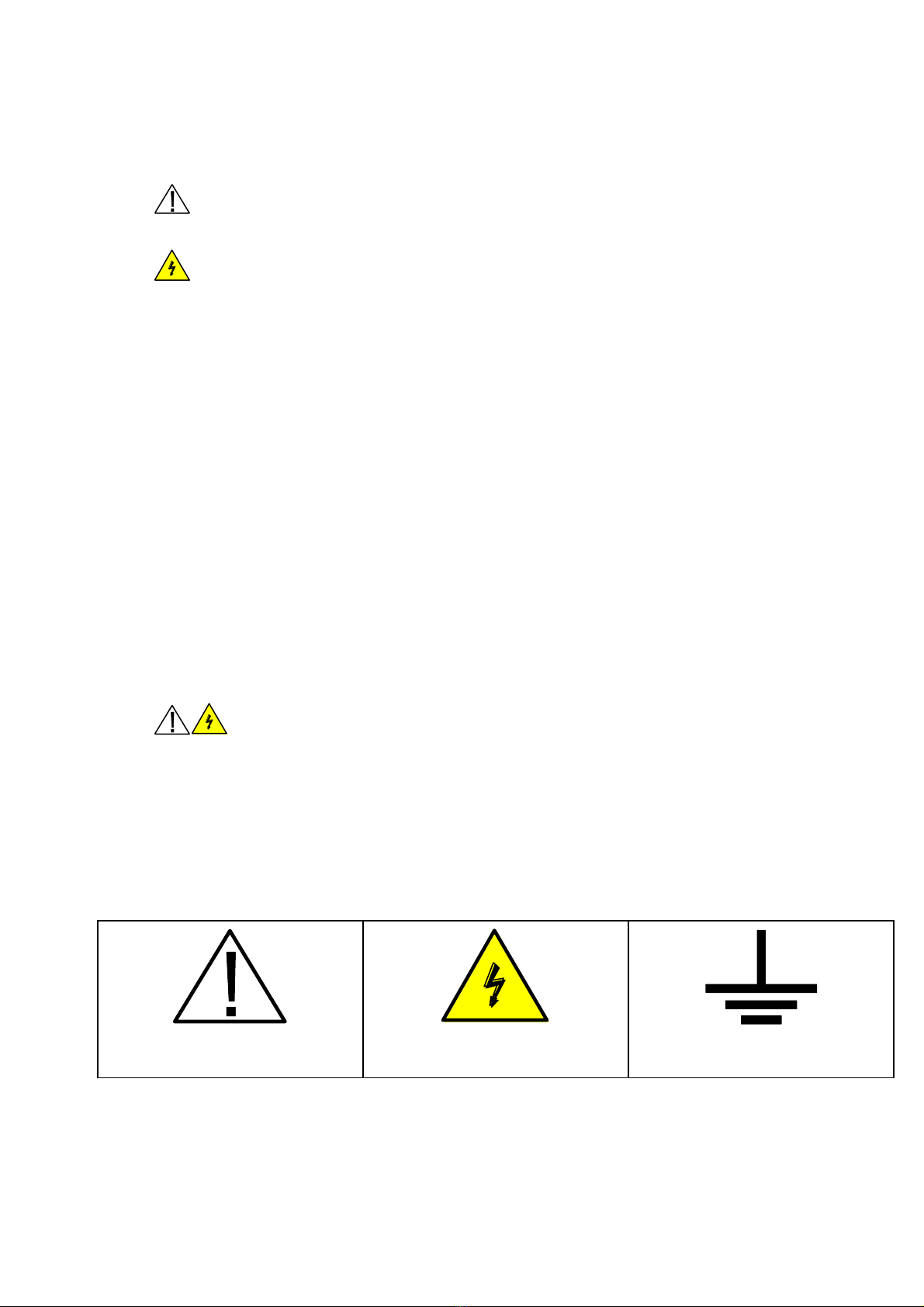
2.4 SAFETY TERMS AND SYMBOLS
You will find the following symbols on this equipment :
2.5 PACKAGING AND REPACKAGING
Your power supply ALR3203 comes with an quickstart guide and its power cable 2 poles + earth type
"EUROPE" : CEE7 / 7 - IEC60320 C13.
CAUTION REFER
TO MANUEL
CAUTION HIGH VOLTAGE
RISK
PROTECTIVE GROUND (EARTH)
TERMINAL
4000 4 362-03-21 5 ENGLISH
3 OPERATING
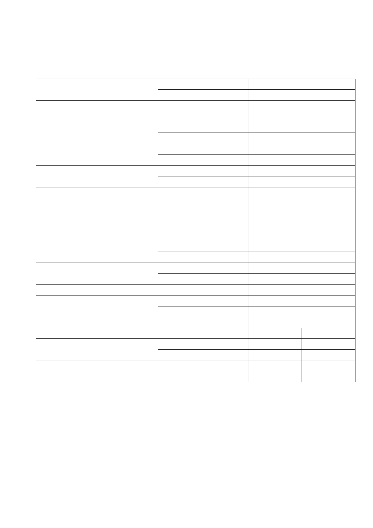
3.1 TECHNICAL FEATURES
The specifications below are given after at least 30 minutes use within the specified operating
temperature range.
Operating
Constant voltage
Automatic
Constant current
Automatic
Mini maxi adjustment
Voltage
0 to 32.00 Volts (0 to ±10mV)
Current
0 to 6.000 Amps
OVP (voltage protection)
0 to 32.20 Volts
OCP (current protection)
0 to 6.100 Amps
Adjustment accuracy
± (% of output + offset)
Voltage
< 0,03% +10 mV
Current
< 0,03% +2 mA
Regulation / Load 10 –90%
Constant voltage
< 20 mV
Constant current
< 1 mA
Regulation / Source ±10%
Constant voltage
< 1 mV
Constant current
< 1 mA
Ripple
Constant voltage
< 1.5 mV
RMS
; < 5mVp-p noise
< 10 mVp-p Pics of commutation
Constant current
< 0.4 mA
RMS
ou 1mAp-p
Accuracy measurement (25°C ±5°C)
± (% of output + offset)
Voltage
< 0,06% or ±10 mV
Current
< 0,06% or ±10 mA
Temperature coefficient
± (% of output + offset)
Voltage
0,01% / °C
Current
0,05% / °C
Resolution
Voltage / Current
4 digits
Time of answer (Load variation)
Load 50 –100%
< 8 ms (±20mV)
Load 100 –50%
< 5 ms (±20mV)
Overvoltage output
ON/OFF source or output
< 0.3V
Voltage programming speed (up) to 1% of the total course
Without load
Load 100%
Rise times
0 –32 V
70 ms
420 ms
0 –16 V
35 ms
128 ms
Fall times
32V –0V
100 ms
8.5 ms
16V –0V
70 ms
7.5 ms
4000 4 362-03-21 6 ENGLISH
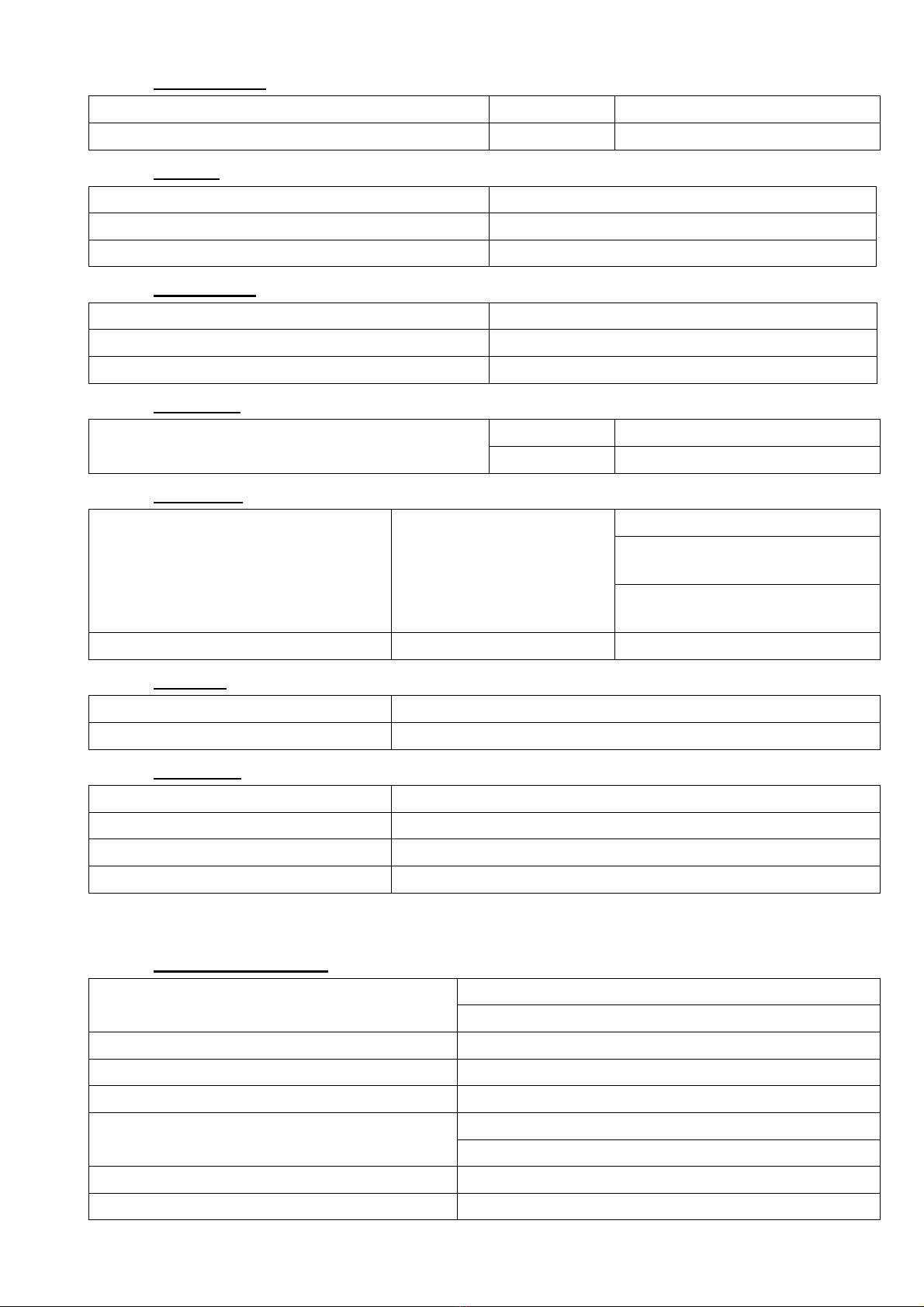
3.1.1 Connections
Outputs + and -
Front panel
Safety terminals Ø4 mm
Ground terminal
Front panel
Safety terminals Ø4 mm
3.1.2 Display
Display
LCD graphic display FSTN N&B 3.2 inch
Resolution
128 x 64 pixels
Backlight
White LED
3.1.3 Protections
Against short-circuits
By current regulation
Against over-temperature
By thermal circuit-braker
Against over-current on main source
By internal fuse (T1.6A ; 250V ; 5x20)
3.1.4 Memories
Memory
Storage
15 configurations
Recall
15 + 1(factory configuration)
3.1.5 Functions
Functions accessible by keypad
7 available
In Voltage or Current
SQUARE periodic
RAMP positive and negative
periodic and single shot
ARBITRARY periodic and
multi shot
Timer (2 Ranges)
Seconde or minute
100 ms to 50 min
3.1.6 Standby
Isolation mode of the output
Enable / disable output
Standby mode
Puts the power supply in standby mode
3.1.7 Interfaces
Isolation / output
150 Vdc
Isolation / Earth
150 Vdc
USB
Serie
Processing time of control
< 20ms
3.1.8 Other caracteristics
Power source
220 –240 Volts ±10%, 50 –60 Hz
EEC socket C14 for cable 2 poles + earth C13 (2P + E)
Maximum power consumption
126W (<4W in Standby mode)
Internal fuses (x2) AC input
5 x 20 ; 250V T1.6A
Efficiency
> 78% of the maxi powerful
Safety
Class I, CAT II, degree of pollution 2
Complies with EN 61010-1, CAT II
CEM
Complies with EN 61326-1 & EN 55011
Voltage on the earth
± 150 Vdc

4000 4 362-03-21 7 ENGLISH
Operating temperature
0°C to + 40°C
Storage temperature
-20°C to + 60°C
Humidity condition
< 85% to 30°C and decrease to 50% at 40°C
Altitude
< 2000 m
Presentation
Front panel with soft-touch keypad, back side with
handle and cord storage area, metallic case with
epoxy finish
Dimensions
95 mm x 174.5 mm x 219.5 mm
Weight
1.38kg
4000 4 362-03-21 8 ENGLISH
4 OVERVIEW
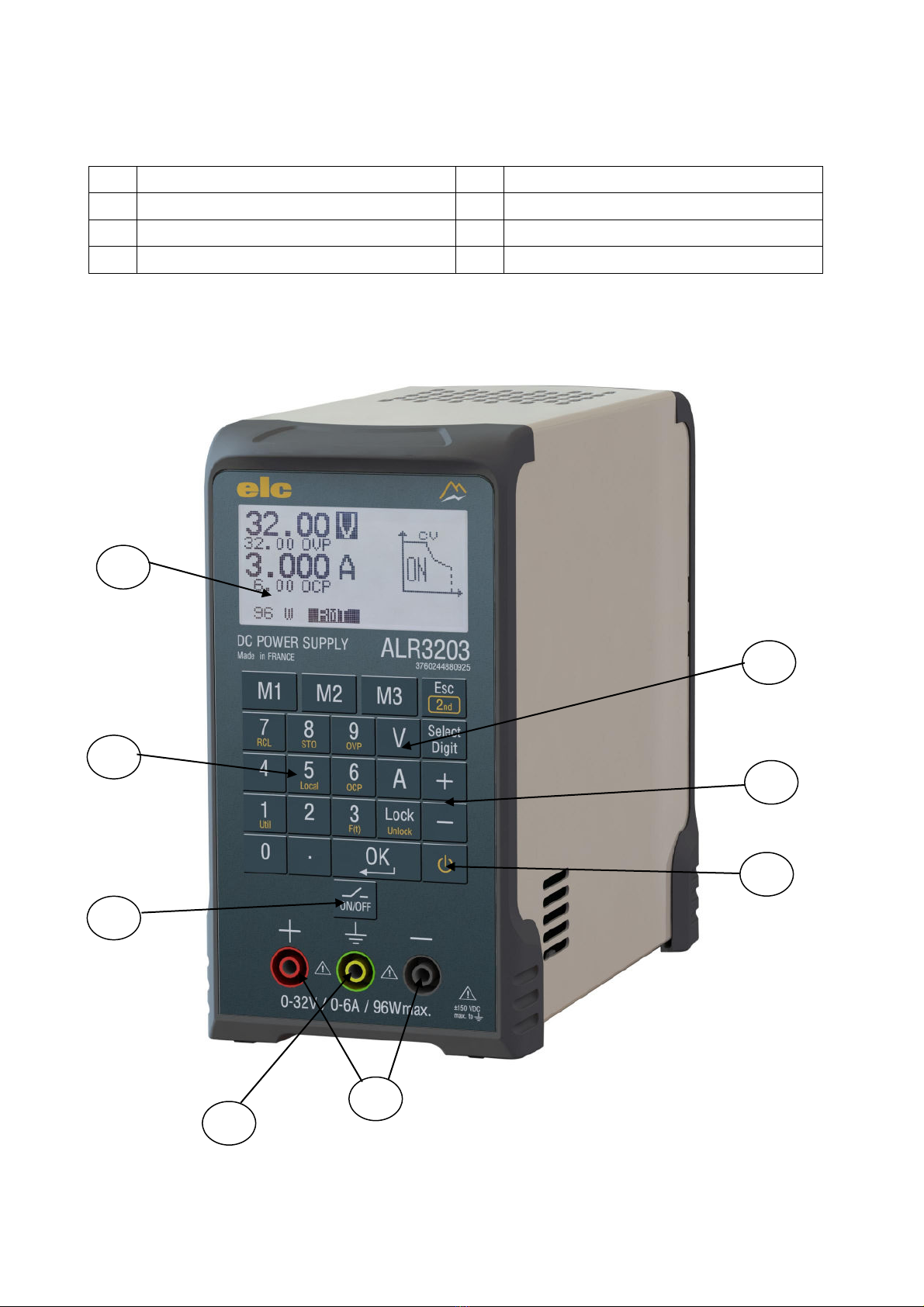
4.1 FRONT PANEL
1
LCD display
2
Keypad double function
3
Functions key
4
ON/OFF output
5
Keys setting
6
Standby
7
Safety socket output
8
Earth socket
2
1
4
8
7
3
5
6

4000 4 362-03-21 9 ENGLISH
4.2 REAR PANEL
9
Handel
10
USB Connector
11
AC power inlet socket
12
Power AC switch
13
Cord storage
9
10
11
13
12

4000 4 362-03-21 10 ENGLISH
5 SHORT DESCRIPTION OF THE FRONT PANEL
5.1 DISPLAY
The basic mode on the LCD display (
1
) shows the value of the voltage and current setting, the
output's powerful, the currently regulation mode (CV or CC) and the output's state (ON or OFF).
If the OVP and OCP stopped are less than the maximum setting (32.20V and 6.100A) they will
be displayed.
The measurement (voltage or current) is displayed instead of the set, if different. Simply touch
on V or A selection keys, displays the operator instructions.
5.2 KEYPAD AND SHIFT
The keypad (
2
) allows directly modifying the set values U and I getting access to secondary functions.
5.3 KEYS CONTROL
The keys (
3
) allows the selection of the set to change and the selection of the dual function keyboard
with shift.
5.4 ON/OFF : GENERAL & STANDBY
The keypad (
4
) allows to enable disable the output. The keypad (
6
) combined with the function ‘’2nd’’
this is the Standby, which is enabled or disabled.
5.5 KEYS SETTING
The keys (
5
) allow a direct change to the set value U and I or navigate through the secondary functions
menu.
5.6 SOUND SIGNAL
Short signal low frequency
: keypad detect [0] to [9].
Short signal medium frequency
: keypad detect function ([V], [A], [OK], …)
Long signal high frequency
: Input value error or safety detect.
5.7 SAFETY SOCKETS CHANNEL
The sockets (
7
) (safety sockets Ø4mm) allow the connection to the output + and –to the load
5.8 EARTH FUNCTIONNAL SOCKETS
The socket (
8
) (safety socket Ø4mm ) allow a functional connection to the earth.
4000 4 362-03-21 11 ENGLISH
6 DESCRIPTION OF CONTROL COMMANDS
6.1 PARAMETERS SETTING
6.1.1 Escape Key
Touch
Allow to go out without taking the value.
If no action, allow access secondary function.
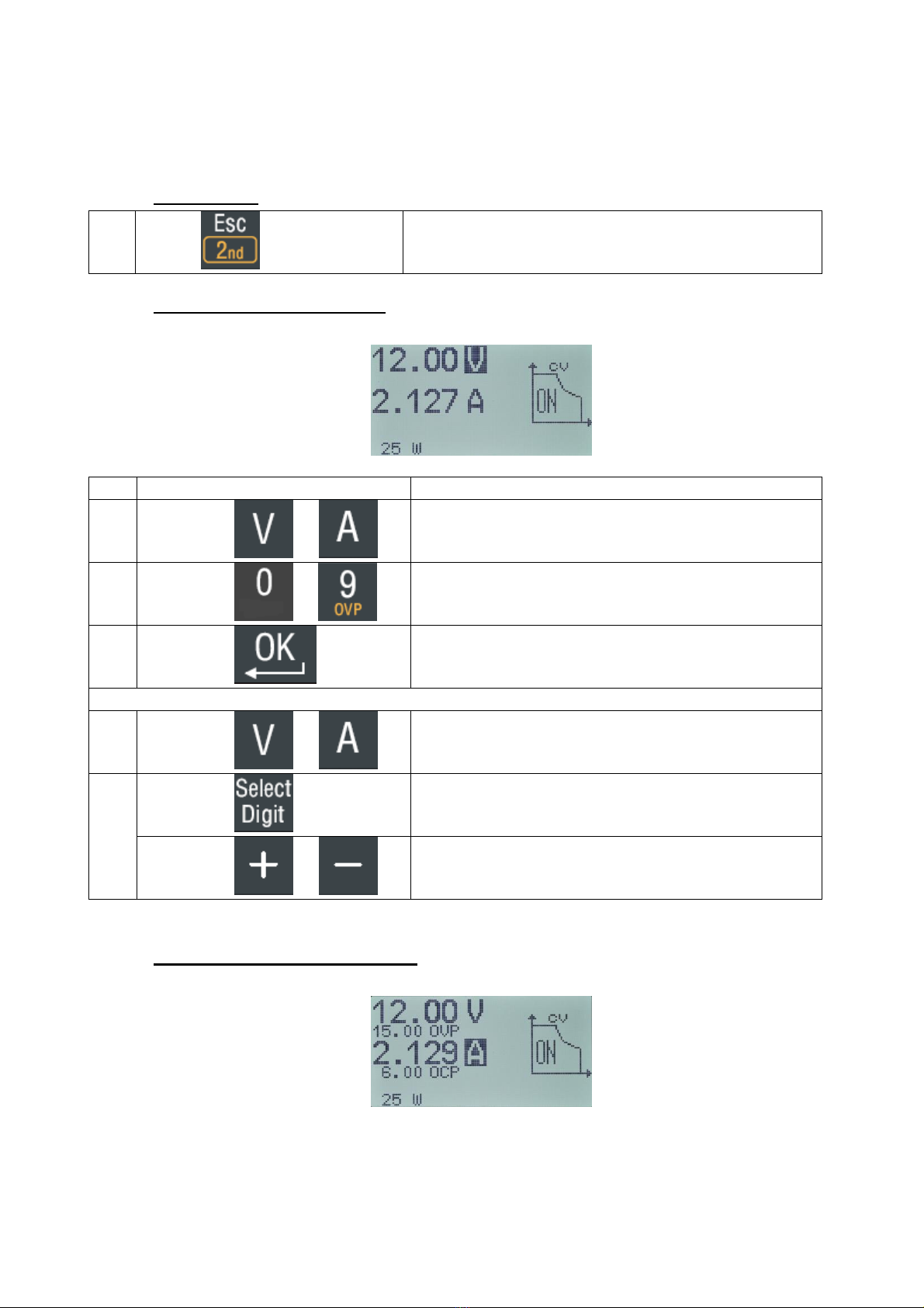
6.1.2 Setting Voltage or Current
Two possibilities :
Action
Description
1.
Touch on or
Select the voltage or current value to change
2.
Touch on to
Enter the value
3.
Touch on
Valid the value
1.
Touch on or
Select the value voltage or current to change
2.
Touch on
Select the 'Digit' to modify by successive push
Touch on or
Change value selected, step by step
6.1.3 Setting the OVP or OCP limits

4000 4 362-03-21 12 ENGLISH
Action
Description
1.
Touch on
Select key “2nd”
2.
Touch on or
Enter the U (OVP) or I (OCP) limit
3.
Touch to
Enter the value
4.
Touch
Valid the value
CANCEL OVP or OCP
1.
Touch on
Select key “2nd”
2.
Touch on or
Enter the U (OVP) or I (OCP) you need to
cancel
3.
Touch
Cancel the limit selected
6.1.4 Isolation of output
Action
Description
1.
Touch on
Touch this key disconnect the output.
So, the instructions are then displayed and
editable
4000 4 362-03-21 13 ENGLISH
6.2 MEMORIES
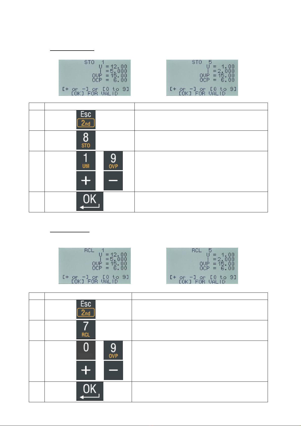
6.2.1 Storage setting
Action
Description
1.
Touch on
Select key “2nd”
2.
Touch on
Select the function “Storage” configuration
3.
Touch on to or
touch on or
Select where to save the current configuration
(1-15).
The display shows the registration number and the
current contents.
4.
Touch on
Stores the current configuration in the storage
number selected.
6.2.2 Recall setting
The memorie “0” recalls a factory configuration and can’t be erased.
Action
Description
1.
Touch on
Select the key “2nd”
2.
Touch on
Select the function “Recall” configuration
3.
Touch on to
Touch on or
Select the configuration number (0-15).
The display shows the contents of the
configuration.
4.
Touch on
Recall the configuration with the output
disconnected

4000 4 362-03-21 14 ENGLISH
Action
Description
1.
Touch on or
Touch on
Recall configuration number 1, 2 or 3.
2.
Touch on
Recall the configuration with the output
disconnected
6.3 CONTROL UTILITIES
This command control includes the following functions :
- Language choice
- Changing the contrast of the display.
- Reset memories
Action
Description
1.
Touch on
Select key “2nd”
2.
Touch on
Select the function “Util”
3.
Touch on to
Touch on or
Select with keys different configuration choices.
4.
Touch on
Valid the choice with “OK”
6.4 PROGRAMMED FUNCTIONS
Enabling this key allows to get to the output, multiple periodic wave forms or not, in
voltage or current mode (see Appendix C).

4000 4 362-03-21 15 ENGLISH
Action
Description
1.
Touch on
Select the key “2nd”
2.
Touch on
Select the function generator, “F(t)”
3.
Touch on
Valid the choice with “OK”
4.
Touch on or
Touch on or
Follow the choices
5.
Touch on
Valid the choice with “OK”
6.5 OTHER FUNCTIONS
6.5.1 Sleep mode
"Standby" mode is available on the front panel. This mode reduces the current
consumption if the power supply is ON but not used.
Action
Description
1.
Touch on
Select the key “2nd”
2.
Touch on
Sleep mode ON
The backlight is OFF
3.
Touch on
Go out the sleep mode
The backlight comes back after few seconds
6.5.2 Locked and unlocked keyboard
Two possibilities :
Hold on the key "5"
Without a connection to a computer, touch on "Local"
Action
Description
LOCKED / UNLOCKED
1.
Touch on during 4s
Active the locked or unlocked keyboard
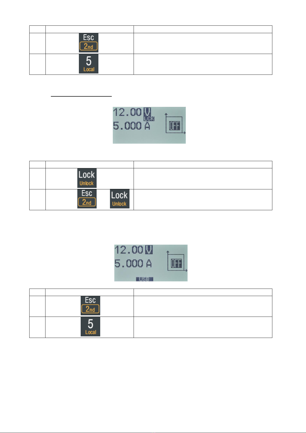
4000 4 362-03-21 16 ENGLISH
Action
Description
1.
Touch on
Select the key “2nd”
2.
Touch on
Active the locked "RMT" or unlocked keyboard.
(control via USB or RS485)
6.5.3 Locked setting value
Locked setting voltage value
Action
Description
1.
Touch on
Press key ‘Lock’ until displaying “LCK” for locked
setting value
2.
Touch on and
Press key ‘Unlock’ until erase “LCK” on display
for unlocked setting value
7 PC control
The activation or deactivation of control via USB:
Action
Description
1.
Touch on
Select the key “2nd”
2.
Touch on
Enable or disable the takeover via the serial
USB port.
You will find the list of commands in APPENDIX A

4000 4 362-03-21 17 ENGLISH
8 MAINTENANCE
No particular maintenance is required for this instrument.
Avoid : dust, humidity, shocks ; your instrument will appreciate it.
For the cleaning, please use a smooth duster.
8.1 TROUBLESHOOTING
If indicators do not light up on switching on, check :
- The mains connection
- The replacement of the cord can be realized only with the model : 3G0.75mm² ;
H05VV-F ; CEE7/7 –IEC60320 C13
- The mains voltage
- That the ON switch is pressed
8.2 ERROR MESSAGE
If following messages appear on the display, please contact the after sales service.
Message
Possible cause
“FAULT : FAILURE START-UP VOLTAGE”
Internal auxiliary power doesn’t work
“UNREGULATED CURRENT/VOLTAGE
PROTECTION”
Internal stage power doesn’t work
9 AFTER SALE SERVICE
The after sales service is ensured by the elc company.
During two years, spare parts and workmanship are guaranteed. This guarantee does
not apply to instruments presenting defects or faults caused by an improper use
(wrong mains voltage, shocks ...) or which have been repaired outside our factory or
the repair shops of our authorized agencies.

4000 4 362-03-21 18 ENGLISH
10 DECLARATION OF CONFORMITY
Manufacturer : elc
Address : 59 avenue des Romains 74000 Annecy France
Declares the product
Name : DC POWER SUPPLY
Type : ALR3203
conformable to the requirements of the directives:
Low voltage 2014/35/UE, Electromagnetic Compatibility 2014/30/UE and
RoHs 2017/2102/UE.
The following harmonized standards have been applied :
Safety : EN 61010-1:2010
EMC : EN 61326-1:2013
Annecy March, 2021
H.CURRI, Manager
ELIMINATION OF MANUFACTURING WASTES BY THE PRIVATE USERS IN THE
EU
This symbol written in the product or in its packaging indicates that
this product must not be throw in the garbage with your other
waste.
Its your responsibility to rid of your manufacturing wastes bringing
it to a specialized sorting office for the recycling of electrical and
electronic instruments.
Collection and recycling separated of your wastes will contribute to
preserve natural resources and guarantee a recycling respectful of
the Environment and human health.
For further information concerning the recycling center near your
place of residence, contact your town hall, the elimination service
of garbage heap or the store where you bought the instrument.

4000 4 362-03-21 19 ENGLISH
APPENDIX A –OPERATING CODES
Commands control format :
[address] <SP>Parameter<SP>Command<SP>[Value]<CR>
[address] = character ASCII 0 (port USB)
Parameter = IDN –SERIAL - VOLT - CURR - OVP- OCP - OUT- RCL - STO - REM -
MODE (ASCII character).
Command = WR - RD - MES (ASCII character).
<SP> = 20h (space).
[Value] = ASCII character.
<CR> = 0Dh (return)
Example 1 : 0 VOLT WR 1250Writing setpoint 1,25 V on USB port
Example 2 : 0 CURR MES
Current measurement request on USB port
Answer :
[address] <SP>Status<SP>Value<CR>
[address] = character ASCII 0 (USB)
Status = OK- ERR- Local (ASCII character).
OK Command valid.
ERR Syntax error in the command.
LOCAL Command impossible, the power supply is in local mode.
<SP> = 20h (space).
[Value] = characters ASCII.
<CR> = 0Dh (enter)
Example 3 : 0 OKBack of example 1
Example 4 : 0 OK 450Back of example 2 current measurement : 450 mA
Command & Answers
Description
Command :
[Address] VOLT WR [0-32200]
Answer :
[Address] OK
Writing the voltage setpoint in mV.
Command :
[Address] CURR WR [0-6100]
Answer :
[Address] OK
Writing the current setpoint in mA.
Command :
[Address] OVP WR [0-32200]
Writing the limit voltage setpoint in mV.

4000 4 362-03-21 20 ENGLISH
Command & Answers
Description
Answer :
[Address] OK
Command :
[Address] OCP WR [0-6100]
Answer :
[Address] OK
Writing the limit current setpoint (mA) channel 1,
In double mode.
Writing the limit current setpoint (mA) in serial, parallel
or tracking mode.
Command :
[Address] OUT WR [0-1]
Answer :
[Address] OK
Disconnect / Connect the output.
Command :
[Address] RCL WR [1-16]
Answer :
[Address] OK
Recall the configuration memorised.
Command :
[Address] STO WR [1-16]
Answer :
[Address] OK
Save the usual configuration.
Command :
[Address] REM WR [0-1]
Answer :
[Address] OK
Mode ‘Local’ => 0.
Mode ‘Remote =>1
Command :
[Address] VOLT RD
Answer :
[Address] OK [0-32200]
Reading the voltage setpoint in mV.
Command :
[Address] CURR RD
Answer :
[Address] OK [0-6100]
Reading the current setpoint in mA.
Command :
[Address] OVP RD
Answer :
[Address] OK [0-32100]
Reading the limit voltage setpoint in mV.
Other manuals for ALR3203
1
Table of contents
Other ELC Power Supply manuals


