BIELMEIER KH 17101 E User manual

INSTRUCTIONSFORUSE
Kitchen extractorhood
Type:
KH17101 E, KH17106 E
2
DearCustomer!!
You arenowauserofthenewestgeneration kitchenextractor
hood ofKH17101, KH17106.
Thishood hasbeendesignedand manufacturedspeciallywitha
viewtosatisfying yourexpectationsand it will certainlyconstitutea
fitting elementofamodernkitchen.Themodernstructuralsolutions
and thenewesttechnologiesusedinproduction ofthishood
guarantee itshigh effectiveness and good appearance.
Pleaseread theseinstructionscarefullybeforeinstalling the
hood.They will make you avoidmistakesduringinstallation and
operation ofthehood.
Wewishyou alotofsatisfaction fromchoosing ourkitchen
extractorhood.
CONTENTS
ICharacteristics3
II Components 3
III Technicaldata 4
IV Operatingconditions 4
VInstallation 5
1. Installationof thewallhanger 6
2. Installationof thehood 6
3.Connectingtothepowernetworkandoperationcheck 7
4. Settingtheoperationmodeof thekitchenextractorhood 7
4.1. Settingtheairextractormodeof operationof thehood 7
4.2. Settingtheodour absorbermodeof operationof thehood 7
4.3Fanspeeds 7
VI Operationand maintenance 8
1. Operationalsafety 8
2. Operation 8
2.1. Controlpanel 8
2.2. Programfunction 9
3. Maintenance 9
3.1. Metal greasefilters 9
3.2. Carbonfilter 10
3.3. Lighting 10
3.4. Cleaning 11
Notes 12

3
I. Characteristics
KitchenextractorhoodKH17101, KH17106 wasdesignedtoremovekitchen
fumes.Itrequiresinstallationofaconduit dischargingusedairtotheoutside.The
conduit (usuallyapipe 150 mm)shallnotbelongerthan4-5m.Thehoodcanoperate
asanodourabsorberafterinstallationof anactivecarbonfilter.Insuchcaseaconduit
discharging usedairtotheoutsideisnotnecessary,butit isrecommendedtoinstallan
airexhaustguide.
Thekitchenhoodisanelectrical appliance manufacturedaccordingtoclass II
ofshockprotection.
Ithasitsownlightingandanexhaustfanwhichcanbesettooneofthree
rotationalspeeds.
Thehoodwasdesignedforpermanentinstallationonavertical wall overagas
orelectriccooker.
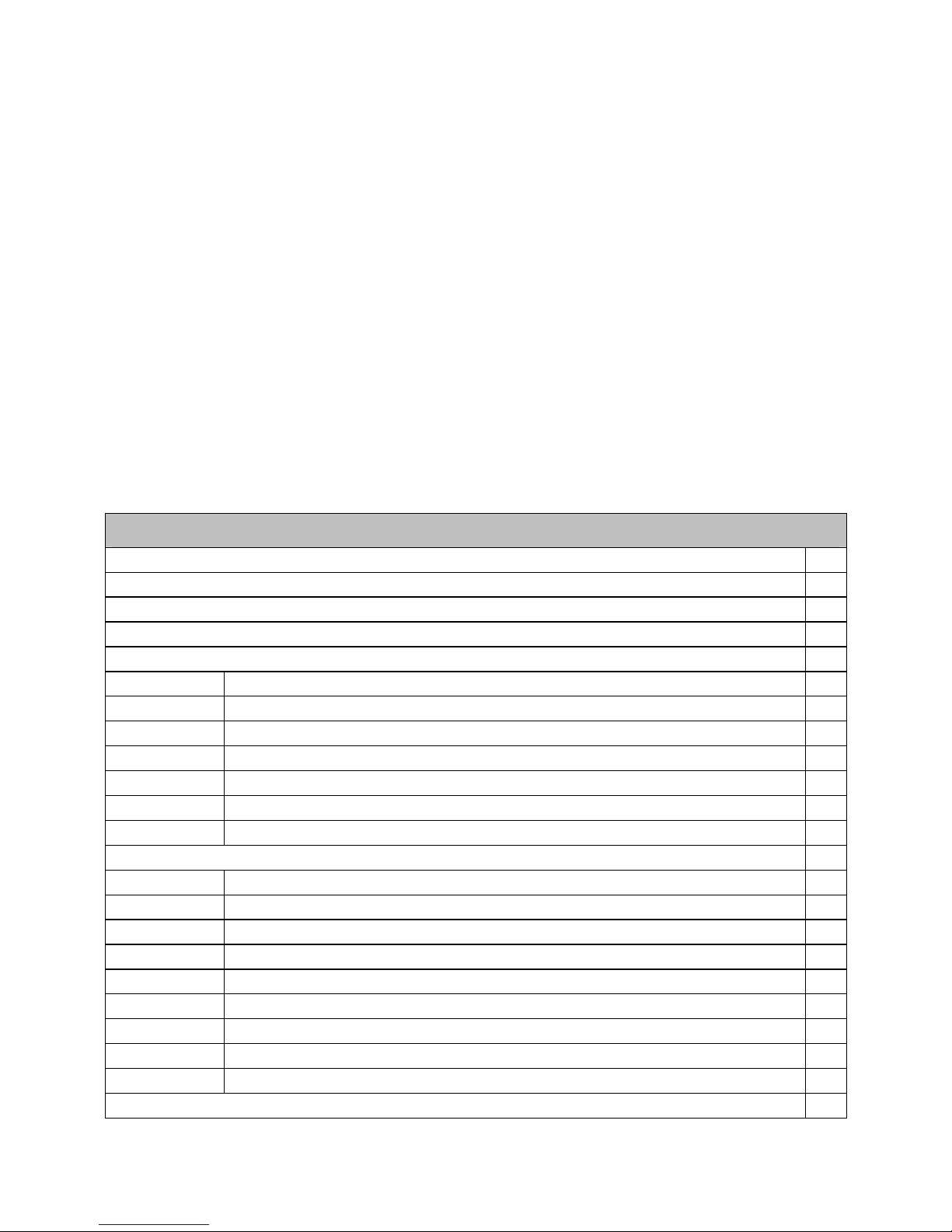
II. Components
Thehoodconsistsof thefollowingelements(Fig. 1):
A. Hoodbodywithaglass [A], equippedwithlightsand thefanunit,
B. Thedecorativecoverconsistingof thetopfunnel Candthebottomfunnel
D,
C. Wallhangerof thehood[B]and thehangerof thetopdecorativecover
[E],
D. Airexhaustguide[F],
E. Setof mounting plugs.

4
III.Technicaldata
Type
Characteristic
KH 17101 KH 17106
Supplyvoltage AC230V50Hz
Fanmotor 1
Lighting Halogenlamps2x20W
Numberof greasefilters 1
Fanspeeds 4
Width[cm] 90 60
Depth[cm] 50
Height[cm] 109 –128
Outlet[ømm] 150 bzw. 120
Capacity[m 3/h] max.900
Powerconsumption[W] 240
Noiselevel[dBA] max.51
Operationalmode Extractororabsorber
Colour INOX
IV. Operatingconditions
1.Thekitchenhoodwasdesignedforremoval ofkitchenfumestotheoutside.It
shouldbeconnectedtoanappropriateventilationduct(donotconnectthehoodtoany
chimney, smokeorflue-gasductswhichareinuse).
2.Thedeviceshallbeinstalledat thedistance ofat least450 mm abovetheworking
topof anelectriccookerand 500 mm-of agascooker.
3.Donotleaveopenflameunderthehood.Whenremovingpotsfromtheburnersset
theflametoitsminimumlevel.
4. Anyfoodcookedinfat shallbeconstantlymonitored, sinceoverheatedfat canignite
veryeasily.
5.Thegreasefilterof yourkitchenhoodshouldbecleanedatleastevery2months,
becauseafiltersoakedwithgreasebecomeseasilyflammable.
6.Pulltheplug of thepowercordfromawall socketbeforeanycleaning,filter
replacementorrepairoperation.
7.Ifanyothernon-electricdevicesareusedinthesameroomasthehood(e.g.liquid
fuelovens,flow-through orvolumetricwaterheaters),itisnecessarytoprovide
appropriateventilation(airsupply).Safeoperationispossiblewhenduring
simultaneousoperationof thehoodandcombustiondevicesdependentonairsupply
thenegativepressureof notmorethan0.004 milibarismaintainedatthelocationof
thesedevicesinsidetheroom(thispointdoesnotapplywhenthehoodisusedasan
odourabsorber).

5
8. Whenconnecting to230Vpowersupplynetworkuseanelectricsocketinworking
order.
V. Installation
Toinstall thehoodproceedas
follows:
1. Installthewall hanger[B]at the
appropriatelevel.
2. Hangthehoodbody[A]onthe
hanger[B]
3. Connectthehoodtothe
ventilationduct.
4. Connectthehoodtothepower
network.
5. Installthewall hanger[E]atthe
appropriatelevel.
6. Installthetelescopiccolumnofthe
masking cover.
6
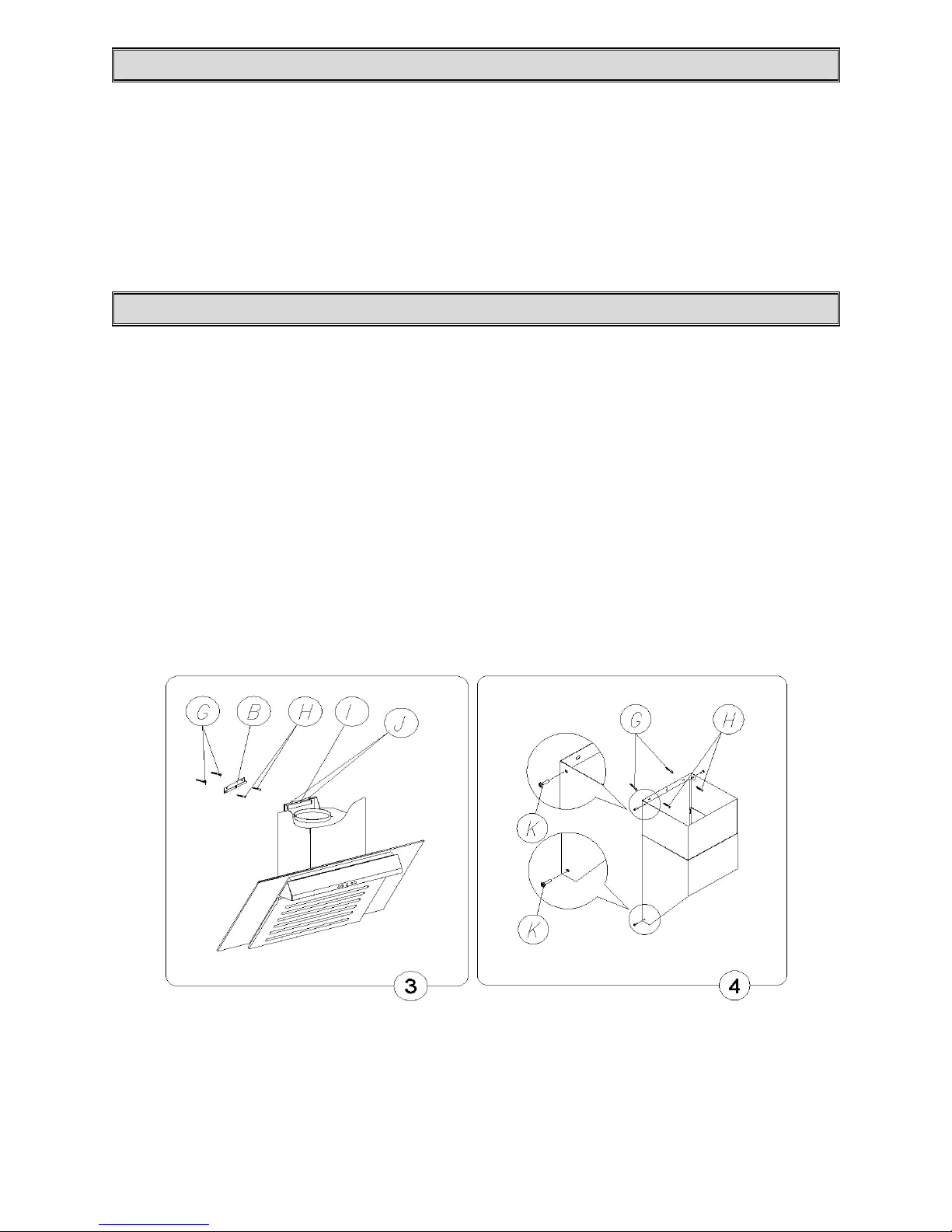
1. Installationofthewall hanger
a) Trace averticallineonthewalltoindicatethecenterof thecookerplate,
b) Holdahoodhangerprofile[B]tothewall (Fig.3,and3),setit symmetricallyin
relationtothecentral line,withthedistance betweentheholesintheprofileand
thecookerplateamountingtomin.970 mm,leveltheprofilepreliminarily,
indicatethespacingof mountingholesonthewall,
c) Drill theholesasindicatedonthewall,usingdrillsof diametercorresponding to
theattachedexpansionplugs,drivetheplugsinand thenscrewthehangerprofile
tothewall,
2. Installationofthehood
a) Hangthehoodbodyontheinstalledhanger[B],levelit withadjusting screws[J]
andthentightenthescrew[I] preventingthehoodfromslidingoffthehanger,
b) Ifrequired,installtheappropriateconduitfordischargeof airtoaventilationduct,
c) Attachthetelescopingcolumnof themasking cover[C and D]onthemounted
hood(Fig.1)
d) Extendthetopmaskingcover[D](Fig.4) totherequiredheight,indicateitsmax.
reachonthecenterline, removethecover,
e) Holdthehangerof thetopmaskingcover[E]at thecenterline,atadistance of 63
mm fromtheindicatedpointof max.reach(Fig. 4),indicatethemounting holeson
thewall andinstallthehangerasdescribedunderd).using thesamemounting
screws,
f) Installthemaskingcovercolumnagainand,using apprpriatescrews,fixit tothe
bottommaskingcoverandthetophangerprofile,
g) Connectthehoodtothepowersupplynetwork.
7
3. Connectingtothepowernetworkand operationcheck
Afterconnectingthedevicetothepowersupplynetwork(inaccordance with
therequirementsdefinedabove)it isnecessarytocheckthelightingof thehoodand
whetheritsmotorworkscorrectly.
Thewall socketshall beaccessiblefordisconnecting theplugafterthehoodis
installed.
4. Settingtheoperationmodeofthekitchenextractorhood
4.1Settingtheairextractormodeofoperationofthehood
Intheextractormodeairisdischargedtotheoutsidebyaspecial conduit.Inthat
settinganycarbonfiltersshallberemoved.
Thehoodcanbeconnectedtotheopening discharging airtotheoutsideby
meansof arigidorflexibleconduit of 150 mmdiameter,andappropriateclampsfor
conduitswhichshouldbepurchasedinashopselling installationmaterials.
Aqualifiedinstallershouldbecommissionedtomaketheconnection.
4.2Settingtheodourabsorbermodeofoperationofthehood
Inthisoptionfilteredairreturnstotheroomthroughcutoutsonbothsidesof the
topfunnel.Inthissettingitisnecessarytoinstall thecarbonfilter(KF 17134);
installationof theairexhaustguideisrecommended.
4.3Fanspeeds
Thelowestandmediumspeedsshouldbeusedundernormalconditionsand
withlowconcentrationof fumes.Thetopspeedshouldbeusedincaseof high
concentrationof kitchenfumes, e.g.during fryingorgrilling.
VI. Operationand maintenance
1. Operationalsafety.
All safetyinstructionsincludedinthismanualshallbeobservedwithout
exception!
Greasefiltersandactivecarbonfiltersshouldbecleanedandreplaced
accordingtomanufacturer’sinstructions, ormorefrequentlyinperiodsofintensiveuse
(morethan4hoursaday).
Ifagascookerisusedit isforbiddentoleaveuncoveredflame.When
removingpotsfromgasburnersset theflametoitsminimumlevel.

8
Alwaysmakesurethatflamedoesnotextend outsidethepot.Suchasituationcauses
undesiredenergylossesanddangerousheatbuild-ups.
Thehoodshouldnotbeusedforotherpurposesthanthoseforwhichitwas
designed.
2.Operation
2.1. Controlpanel
Operationof thehoodcanbecontrolledbymeansof acombinedswitch.
Fig.4
-Digital display-informsabouttheselectedspeedofhoodoperationand/or
actuationof theswitch-offtimer(TIMER).
-„+”,„-”,-motorspeedselectionbuttons.
-„T” –switch-off timer–„TIMER”-automaticswitching offofthehoodmotor
afterpreselectedtimedelay.
-„L”–lightingon/off.
2.1Programfunktion
Timer function: KH17101,KH17106kitchenextractorhoodisequipped
withtheoptionof programmingautomaticswitch-offofthehoodfanin10-minute
intervals,uptomaximumdelayof90 minutes.
Timerisactuatedbypressing„T” buttonduringoperationofthehoodwiththe
requiredfanspeed.Thedisplaywill flashandadotwillappearindicating thatthe
deviceisintheswitch-offtimeprogrammingmode.Thenyoucanprogramthetimeof
automaticswitch-off ofthehoodmotorusing+button,keepinginmind that thefigure
shownonthedisplaymultipliedby10-minutetimeinterval indicatesthemotorswitch-
offdelay(e.g.:1=10minutes, 2=20minutes, 3=30minutes,etc.).
Aftersettingthedelayit hastobeconfirmedbypressingTbuttonagain.The
displaywill stopflashingandwill showthepreviouslysetspeed,andthepulsatingdot
will indicatethatthetimetoswitchingoffofthehoodmotorisbeingcounted.
TIMERfunctioncanbecancelledbypressingTbuttonagainduringcounting
ofthetime.
NOTE:Theprogramalwaysmemorizesthelastdelaysetting.

9
TIMERfunctionhastobeactuatedwithin20 seconds, otherwisethehoodwill
return automaticallytonormaloperation.
Themicroprocessorsystemmaygetdeletedorcrashduringmomentary
voltagedropsinthenetwork,andstopresponding tocommandsfromthekeyboard.In
suchcasethehoodhastobedisconnectedfromandthenconnectedagaintothepower
networkinordertoresetthesystem.
3.Maintenance
Regularmaintenance andcleaningof thedevice will guarantee itsgoodand fault-less
operation,and extenditslife.Attentionshouldbepaidtoreplacinggreaseandcarbon
filtersaccordingtomanufacturer’sinstructions.
3.1Metalgreasefilters
1.Cleaning.
Greasefiltersshouldbecleaned
everytwomonthsduring normal
operationof thehood,ina
dishwasherormanually,using
milddetergentorliquidsoap.
2. Replacement(Fig. 5).
Todismantlethefilterproceedas
follows:
a)removethebottomcoverby
releasing thelockcatch,
b)removethemetalgreasefilter
3.2.Carbonfilter (KF17134)
1. Operation.
Carbonfilterscanbeusedonlywhenthehoodisnotconnectedtoanyventilationduct.
Filterswithactivecarboncanabsorbodoursuntiltheyaresaturated.Theycannotbe
washedorregeneratedand shouldbereplacedatleastevery2monthsormore
frequentlyincaseof veryintensiveuse.
2.Replacement.
a) Removethemetalgreasefilter,
b) Removethecarbonfiltersituatedinsidethehood, onthealuminiumfilter
c) Installanewfilteronthealuminiumfiltercasing proceeding inreverseorder
tosection(Fig.7).

10
3.3. Lights.
Thelightingsystemconsistsoftwohalogenlamps
of20 Wpowereach.
Toreplace alightbulbproceedasfollows:
a) Usingaflattoolorscrewdriverprisethering
holding thehalogenlampglass (Fig.8) and,
holding it,removetotheoutside.
b) Replace thebulbusingapiece ofclothor
paperforthatpurpose.
c) Thenreinstall thering andtheglass
proceedinginreverseorder.
Note:Makesure thatyoudonottouchthehalogenbulbtobe
installedwithyourbare fingers!!!
3.4. Cleaning
Thefollowing shallbeavoided duringnormalcleaning of thehood:
·wetclothorspongeandwaterjet,
·solventsoralcoholswhichmightdulllacqueredsurfaces,
·causticagents,particularlyinregardtocleaning stainless steelelements,
·hard,roughcloth
Itisrecommendedtousmoistclothandneutralcleaning agents.
This manual suits for next models
1
Table of contents
Other BIELMEIER Ventilation Hood manuals

Popular Ventilation Hood manuals by other brands

Electrolux
Electrolux EFI 60011 user manual

GLOBALO
GLOBALO Desolero Operating and installation instructions

Franke
Franke FSTPRO 608 X user manual

Schweigen
Schweigen UM1170-6S1 installation guide

Whirlpool
Whirlpool RH4836XLT1 Use & care guide

ROBINHOOD
ROBINHOOD RO Series Installation and operating instructions


Electrolux
Electrolux EFC 9690 user manual

ROBLIN
ROBLIN VIZIO 900 V BLAC SM Instructions for installation and use

Xpelair
Xpelair DX100B Installation and maintenance instructions

Baumatic
Baumatic AS35SS instruction manual

Best
Best UCB3I30SBW installation instructions

FALMEC
FALMEC Polar Black 35 Instruction booklet