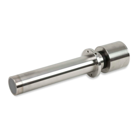
Big Daishowa Point Master Pro PMP-10 User manual

치수 및 주요 사양 MAIN SPECIFICATIONS
그림
Fig.
스타일러스 선단
Material
L L1φd질 량
Weight(g)
2 1
2
3
4
4
2.0
2.0
2.5
2.9
2.6
8
형 번
Model
1
2
28
28
(mm)
센서 헤드
SENSOR HEAD
4-센터 조정 스크류
4-CENTERING SCREW
샹크
SHANK
배터리 캡
배터리
BATTERY
BATTERY CAP
스타일러스
STYLUS
OPERATION MANUAL
POINT MASTER PRO
●스트레이트 샹크 타입
《 STRAIGHT SHANK TYPE》
●PMP-20/PMP-32 ●BBT40-PMP-120/BBT50-PMP-150●BBT30-PMP-115
●HSK-A63-PMP-130
●PMP-10
●BBT샹크 타입
《BBT SHANK TYPE》
●HSK샹크 타입
《 HSK SHANK TYPE》
BBT40-PMP-120
HSK-A63-PMP-130
BBT30-PMP-115
L1L
φD
φ35
28
연속500시간
배터리
Battery
배터리 수명
Battery Life
LR1×2(단5)
CR2×1
CR2×1
BBT30
63
60
BBT40
HSK-A63
65
115
120
130
BBT NO.
HSK NO.
L L1
연속500시간
BBT50-PMP-150 LR03×2(단4)
60
BBT50
150
연속600시간
연속900시간
연속 900시간
φ35
φ35
28
L
BBT No. BBT30 HSK No. L1
L1
φ35
28
L
(주)1.PMP-10은 배터리 수명 관계로 LED는 한곳에만 있습니다.
교환용 스타일러스(별매품) STYLUS FOR THE EXCHANGE(Optional accessories)
본 제품은 스타일러스 부분을 분리 할 수 있게 설계(M3 나사) 되어 있으므로 스타일러스
파손시 또는 가공물 형상에 따라 스타일러스를 교환할 수 있습니다. 별매품으로 하기의
스타일러스를 제공하고 있습니다. 안내드린 제품 이외의 스타일러스는 사용할 수 없습니다.
배터리 장착 방법 TO INSERT BATTERY
배터리 장착전에는 반드시 전극을 확인 하십시오. 전극을 반대로 장착할 경우, 점등
하지 않습니다.
사용전에는 스타일러스를 손으로 가볍게 터치하여서LED(녹색)가 점등하는지를 확인 하십시오.
LED가 점등하지 않거나, 점등이 약할 경우, 배터리를 교환하십시오.
샹크 바닥면의 배터리 캡을(BBT타입은 플 스터드 볼트)를 풀고 부속 되어 있는
배터리를 그림과 같이 넣은후, 배터리 캡을 조여 주십시오.
BR435
+−
LR1×2 (IEC) or N(ANSI)batteries
+−+
+
−
−
LR1×2 (IEC) or N(ANSI) batteries
CR2 battery
배터리의 표면 및 전극 표면이 이물질이 부착하면 배터리가 남아 있어도 LED가 점등하지
않을 수 있습니다. 이 경우 마른 천등으로 이물질을 제거하십시오.
1.To increase the battery life, PMP-10 have one LED only.
φd
φd
L1
ST28 -1P
ST28 -2P
ST28 -3P
ST28 -4P
ST28 -4R
초경
(Carbide)
루비(Ruby)
28
L
L1
플 스터드 볼트의 나사부 단면 및 클램프부에 산화
처리가 되어 있는 경우 연마 종이등으로 닦아 통전
성을 좋게 합니다.
주 의
CAUTION
주 의
CAUTION
연마 부분(산화층 제거)
remove the
chemically oxidized
28
φ4
φ35
Z
XY
OVERTRAVEL
LED (3곳)
LED
THREE PLACE 오버트래블양
OVERTRAVEL
오버트래블양
반복 정도
Repeatability(Probe)
XY 스트로크
XYstroke
Z 스트로크
Zstroke
측정압력
Measuring Pressure
샹크
Shank
스타일러스 (부속품)
Stylus(Standard accessory)
±1μm(2σ)
±12mm
5mm
XY:0.4N Z:1.5N
φ10、φ20、φ32
BBT30、BBT40、BBT50、HSK-A63
ST28−4R
Model
PMP-10
PMP-20
PMP-32
배터리
Battery
배터리 수명
Battery Life
LR1×2(단5)
10
20
32
75
90
80
49
50
60
φD h7 L1L2
형 번
Model
형 번
(mm)(mm)
BR435×1 연속180시간
(NOTE)
L L
측정 범위
Measurement Depth
그림1 Fig.1 그림2 Fig.2
・
・
・
180
continuous hours
500
continuous hours
900 continuous hours
500 continuous hours
900 continuous hours
600 continuous hours
No.0520
EXPORT DEPARTMENT
TEL (+81)-72-982-8277
・사용전에 반드시 본 설명서를 읽어 보시고 사용하시는 분 전원이 언제나 확인 가능한 장소에 보관하여 주십시오.
・본 제품은 품질 및 정밀도에 대한 엄격한 검사를 통과했음을 증명드립니다.
・
Please read these instructions before use and keep them where the operator may refer to them whenever necessary.
・We certify this product has passed our rigorous inspections of quality and accuracy.
OPERATION MANUAL DOWNLOAD SITE
http://big-daishowa.com/manual_index.php
The screw-in(M3) stylus is replaceable. Please change a stylus according to its wear and tear, and
also when a different type of stylus is required. The following styli are available as options. A
stylus except for the following can't be used.
Remove the battery cap at the end of the shank or at the side of the body (the pullstud in case of
BBT shank type) and insert the accessory batteries with the positive end rst. Then tighten the
above battery cap or pullstud.
In case the pull stud is chemically oxidized, please remove
the chemically oxidized surface to increase the conductivity.
Make sure the correct direction of the electrode of the batteries. Inserting them wrong way
around not only disables the operation but also may damage internal electric circuit of the
sensor and become out of order.
Before using, ensure that the green LED lamps illuminate by touching the stylus with a
nger. Replace the batteries in the case the LED lamps do not illuminate brightly or at all.
If the battery or electrode surfaces are contaminated, LED lamps may not illuminate even if
the batteries are not exhausted. Then, clean the surfaces with soft cloth or similar.
・
・
・

사용상의 주의 CAUTIONS IN USE
위 험
DANGER
사용 방법 HOW TO USE
주 의
CAUTION
●일반적인 사용 방법 ●Usual usage
●고정도 측정이 필요한 경우
핸들을 사용하여 스타일러스를 측정면에 천천히 접촉시킵니다. LED가 점등되는 위치
가 스핀들 중심으로부터 스타일러스 볼 직경의 절반을 차감한 위치 입니다.
스트레이트 샹크 타입의 경우, 흔들림 정도가 우수한 유압척 또는 콜렛척으로 파지 할
것을 권장 드립니다.
고정도의 측정이 필요한 경우, 스타일러스 볼이 측정면에 접촉하여서부터 내부 접점이
분리되기까지 발생하는 XY방향 약5μm, Z방향 약2μm의 지연을 고려하여야 합니다.
(XY방향의 지연량은 측정 방향에 따라 다를 수 있습니다.)
링 게이지를 기계 테이블에 장착하고 다이얼 게이지등을 사용하여 중심 좌표를 구합니다.
스핀들 오리엔테이션 위치에서 포인트 마스터를 스핀들에 장착하고 링 게이지의 중심좌표
에서 X방향 및 Y방향을 측정하고 중심 좌표를 구합니다. 포인트 마스터에서 구한 값과
다이얼 게이지에서 구한 값의 편차를 실제 가공물 측정시 보정합니다.
너비 측정의 경우, 링 게이지 또는 블럭 게이지에 표기된 치수와 포인트 마스터로 측정한
치수의 편차(스타일러스 직경 포함)를 실제 가공물 측정시 보정합니다.
●If highly accurate measurement is required
●사용전 흔들림 정도 점검
포인트 마스터 프로를 기계 스핀들에 장착하고 스핀들 오리엔테이션을 해제 합니다.
수동으로 스핀들을 회전시켜 스타일러스의 흔들림이 가장 작은 위치에 세팅합니다.
스타일러스의 흔들림 정도가 큰 경우,
・스트레이트 타입: 척킹을 다시하여도 흔들림 정도가 개선 되지 않을 경우, 하기의
방법으로 센터 조정을 수행하여 주십시오.
・일체형 타입 : 하기의 방법으로 센터 조정을 수행하여 주십시오.
●스타일러스 센터 조정
본체 외주의 4개(90°분할)스크류는 스타일러스 센터 조정용이지만, 제품 출하시
제로 세팅 되어 있으므로 만지지 마십시오. 스타일러스 센터 조정이 필요한 경우,
홀더를 스핀들에 장착하고 스타일러스에 다이얼 게이지(측정 압력 0.2N이하)를
접촉시켜 4곳의 스크류로 흔들림을 제로로 조정하여 주십시오.
●스타일러스의 가동 범위
스타일러스는 XY방향으로 ±12m m , Z방향으로 5mm 스트로크 합니다. 가동 범위
이상으로가동하면 스타일러스 및 본체가 손상되어 측정이 안될 수 있으므로 삼가해
주시기 바랍니다. 또한 스타일러스에 충격을 가하면 스타일러스가 휘거나 내부 접점
이 손상되어 정밀도에 영향 줍니다.
●사용후 관리
장기간 보관하는 경우 배터리를 분리 하십시오.
본체에 부착한 먼지등 이물질은 마른 천등으로 닦아주십시오. 절대 물로 세척하지
마십시오. 휘발유, 신나, 석유류는 본체를 손상 입히므로 사용하지 마십시오.
직사광선을 피하고 그늘지고 건조한 곳에 보관하십시오.
●스타일러스 점검
스타일러스가 확실하게 장착 되었는지를 확인 하십시오. 헐거울 경우 정밀도에
영향을 줍니다.
본기기측정면에공구를급이송으로접근시킬때는여유가있는위치에서
멈추고남은부분은핸들을사용하여천천히이송하십시오.급이송상태로
본기기와충돌할경우본기기및절삭공구,가공물,장비등이파손될수
있으며,파편으로인하여인체에위험을미칠우려가있습니다.
본 기기를 밀링척등에서 탈부착할때, 낙하하지 않게 충분히 주의하여 주십시오.
포인트 마스터를 스핀들에 장착할때 위상이 바뀌(180°등)면 측정 오차가 발생하므로
주의하십시오. 스타일러스의 흔들림 정도가 큰 경우, 정밀한 측정을 할 수 없으므로
아래의 [사용상의 주의]에 기재 되어 있는 방법으로 센터 조정을 수행 하십시오.
・
・
주 의
CAUTION
・
・
오일 홀이 뚤려 있는 플 스터드 볼트는 사용할 수 없습니다. 센터 스루 사양 장비
에서 급유 노즐의 관계로 오일 홀이 있는 플 스터드 볼트를 사용 할 수 밖에 없을
경우 가까운 대리점에 문의하여 주십시오.
정밀도의 유지를 위해 ATC에 의한 공구 교환은 권장하지 않습니다.・
・
・
・
Clamp the Point Master Pro by a precision chuck, such as NEW BABY CHUCK. As
soon as the stylus contacts the measuring surface of the workpiece in ne feed, the LED
lamps illuminate. The position where the LED lamps illuminate rst is half the distance of
the diameter of the stylus ball from the spindle center.
When highly accurate measurements are needed, it is necessary to take into account that
there is a delay (dead zone) of 5μm in XY direction and 2μm in Z direction from contacting
of the stylus ball with measuring surface of the work till detection of touch position by the
internal contact. (Dead travel in both X and Y directions is nonconstant.)
Attach the ring gauge to the machine. Determine the center of coordinates by means of
the optional test indicator. Attach Point Master Pro to the machine spindle and stop the
spindle in the specied position. (M19 : spindle orientation)
Take measurements in X and Y directions from the center position of the ring gauge.
Record the difference between the center position determined by the test indicator and
that obtained by Point Master Pro, which is to be used for operation in the phase of actual
work measurement.
In case of width measurement, record the difference between the dimension indicated on
the ring gauge・gaugeblocks and that measured by Point Master Pro (difference owing to
ball diameter).
A large measurement error will be caused if Point Master Pro, set to the chuck, should
be attached to the machine spindle in a by 180°deviated drive key phase.
Runout of the stylus, if any, makes accurate measurement impossible. Center it in the
method as specied in the Cautions In Use.
Pullstud with a hole through for coolant cannot be used. However, in the case coolant
nozzle of the machine designed for coolant through the spindle does not allow use of a
pullstud without the hole, please contact agent for advice.
It is not recommended to mount the Point Master Pro into the machine spindle through
automatic tool change for maintaining accuracy.
・
・
・
●Check for runout before use
Mount the POINT MASTER PRO into a chuck and attach the assembly to the machine
spindle. Release the spindle orient (M19) and turn the machine spindle slowly by hand.
If the stylus shows a runout, clamp the assembly again by the chuck in position where
runout is the smallest. Unless runout is eliminated, proceed with centering adjustment
in the following manner.
●Centering adjustment of the stylus
There is a centering bolt beneath (4) ø6mm rubber seals around the head of the Point
Master Pro. These centering bolts also function to x the head. Do not touch these
centering screws in normal use, as centering adjustment is completed before delivery.
If adjustment becomes necessary, put an electric micrometer, which measuring
pressure should be 0.2N or less, to the stylus and repeat loosening and tightening (4)
centering bolts until runout measured while the spindle is rotated by hand is eliminated.
We offer centering adjustment at your expense. Please contact agent.
●Stroke of the stylus
The stylus stroke amounts to ±10°in XY-direction and 5 mm in Z-direction. Never push
it beyond the stroke limit. Otherwise, the stylus and the unit body will be damaged to
make measurement impossible.
Never give shock to the stylus, for example by icking with nger. Otherwise, the stylus
will be bent or the internal contact will be damaged to lower measurement accuracy.
●Care after use
・Remove batteries from the Point Master Pro to be stored for an extended period.
・Wipe off any dirt from the unit body with a dry soft cloth. Cleaning with gasoline,
thinneror any other medium of petroleum basis causes damage to the unit body.
Never wash it with water.
・Store Point Master Pro in a dry place free from high temperatures.
●Check of the stylus
Check the stylus for any looseness. A loose stylus lowers measurement accuracy.
Retighten it as required.
When the Point Master Pro approaches the workpiece at high feed rate, it should be
arrested at sufciently safe distance to allow the nal approach at ne feed by utilizing a
handle. Should the Point Master Pro collide with the workpiece at high feed rate then
damage may be caused and broken parts could endanger persons in the area.
Care should be taken when mounting or dismantling the Point Master Pro to or from the
chuck in order to prevent it falling.
・
・
This manual suits for next models
6
Table of contents
Other Big Daishowa Accessories manuals

