Ryval Hoops C872 Series User manual

C872 Series
ADJUSTABLE HEIGHT
GOAL SYSTEM

2
Thank you and congratulations for purchasing a Ryval Hoops Goal
- the finest basketball goal system on the market today! You will
discover that Ryval Hoops is unsurpassed in product innovation, quality
and integrity in the basketball equipment industry. We are focused on
designing, engineering and products that meet and exceed expectations
of today’s toughest playing environments and demanding players.
Consider the following to determine where to install the basketball goal:
Whether the goal is to be installed into a landscaped area next to the
playing surface or into a hard-surfaced area.
Backboard size and its extension distance from the structures.
If court markings are to be used.
Amount of playing surface desired beneath the goal.
Other functions of playing surface (such as driveway, tennis court, etc.)
WWW.RYVALHOOPS.COM 1 - 8 0 0 - 7 8 7 - 0 6 5 5

3
WWW.RYVALHOOPS.COM
1 - 8 0 0 - 7 8 7 - 0 6 5 5
Consult Ryval Hoops if you do not

4
WWW.RYVALHOOPS.COM 1 - 8 0 0 - 7 8 7 - 0 6 5 5
a. Dig a hole 48" deep and 21"x 21"square . The edge of the hole
should be flush with the edge of the playing surface. If you live in an area
where heavy frost can occur, it may pose a problem, consult your local
building inspector to determine the appropriate hole depth.
b. Build a form before pouring the concrete pad, to ensure that the top
of the concrete remains straight and square. The form should
be placed about 1/2" above the playing surface to allow for water drainage.
c. Bell out the bottom of the hole.
NOTE: The hole must be at least 48" deep.
NOTE: A square hole prevents the rotation of the concrete.
NOTE: The area behind the playing surface must be cleared off by at least
3 feet to enable the user to stand behind the pole to adjust the Rim height.
NOTE: At rim height 10 foot, distance from the face of backboard to
the front of Main Post (A) is 48". Use these specs to calculate desired
backboard overhang of driveway/court.
STEP A 21"
21"
48"

5
WWW.RYVALHOOPS.COM
1 - 8 0 0 - 7 8 7 - 0 6 5 5
STEP B
A. Thread a 16mm Hex Nut (U4) onto each of the 16mm J-Bolts
(U2).Securely tighten the Nuts all the way down to the end of the
threads.
B. Slide the threaded end of the J-Bolts through the holes
in the Anchor Template (U1) and secure each J-Bolt with a
16mm J-Bolt Hex Nuts(U4) as shown. Securely tighten all Nuts
at this time.
U2
U4
U1
U2
U2
U2
U4
U4 U4
U4
U2
NOTE: Make sure the curved“J”ends of the J-Bolts are
oriented in a rectangular pattern, as shown.
STEP C
a. Mix the concrete according to the instructions on the bags. Note that
a thicker mix of concrete will dry stronger than a thin mix. Pour the
concrete into the hole, stopping approximately 18 inches from the top
of the hole.
b. Insert the four pieces of Anchor Rebar (U5) into the hole, pushing each
piece firmly to the bottom of the hole. The four pieces should be
arranged in a square approximately 8 inches wide so that each piece of
rebar will be positioned next to the J-Bolts when the J-Bolt Template
is placed in the cement.
c. Finish filling the hole to the top with concrete. The top of the concrete
should reach just above the level of the top of the form.
P

6
11/16" and 3/4" Sockets or Wrenches
15/16" and 17/16" sockets or Wrenches
WWW.RYVALHOOPS.COM 1 - 8 0 0 - 7 8 7 - 0 6 5 5
STEP D
a. Position the J-Bolt Template (U1) over the hole so that it is centered,
with the sides of the plate square with the sides of the hole.
b.Push the J-Bolts (U2) into the concrete until the J-Bolt Template is
resting flat against the surface of the concrete.
c. Grasp the tops of the J-Bolts and agitate the Template assembly back
and forth repeatedly to eliminate any air bubbles in the concrete. Lift the
Template slightly above the concrete when agitating . Make sure the
Template is resting on the concrete after agitating. Form the concrete
into a downward slope away from the Pole to allow water runoff.
d. Clean off any concrete that may be on the J-Bolt Template or the exposed
portions of the J-Bolts.
e. Using a carpenter’
s level, make sure the Template is square to and level
with the playing surface.
f. Allow the concrete to cure for a minimum of 5-7 days before installing
the rest of your basketball system. In cold , wet weather or humid
climates, allow additional time for the concrete to cure.
YOU ARE NOW FINISHED WITH THE INITIAL ASSEMBLY STEPS. DO NOT PRO-
CEED WITH THE ASSEMBLY UNTIL THE CONCRETE HAS FULLY CURED . CUR-
ING WILL TAKE A MINIMUM OF 72 HOURS. IN HUMID CLIMATES OR WET
WEATHER, ALLOW ADDITIONAL TIME FOR THE CONCRETE TO CURE.
! !
WARNING
NEVER USE THE SYSTEM WITHOUT FOLLOWING THE CEMENTING INSTRUCTIONS . FAILURE TO
FOLLOW ALL OF THESE INSTRUCTIONS AND WARNINGS COULD LEAD TO SERIOUS PERSONAL INJURY
OR PROPERTY DAMAGE AS LISTED ON PAGE ONE.
U1
U2

ITEM QTY DESCRIPTION
A 1 6"x6"Main Post
B 1 Actuator
C 2 Spring-Assist Cartridge
D 1 Pole padding
E 1 Gusset Padding
F 1 Main Extension Arm ITEM QTY DESCRIPTION
G 2 Upper Extension Arm 1 2 Nylon Washer M18
H 1 Backboard 2 9 Nylon Washer M16
I 1 Safety rod 20mmdia 3 2 Nylon Washer M12
J 1 Sleeve for Spring Cartridge 4 1 6mm Lock Pin
K 1 Rim Height Indicator 5 2 Hex Bolt M18x320mm
L 1 Flex Rim (Separate pack) 6 1 Hex Bolt M16x295mm
M 1 Rim Pad (Pre-attached) 7 2 Hex Bolt M16x320mm
N 1 Rim Height Sticker 8 1 Hex Bolt M16x185mm
9 1 Hex Bolt M16x135mm
U1 1 Anchor Template 10 2 Hex Bolt M12x35mm
U2 4 16mm Anchor J-bolts 11 4 Washer for M18 Bolt
U3 8 Thick washer for J-bolts 12 10 Washer forM16 Bolt
U4 12 Hex nut M16 13 4 Washer forM12 Bolt
U5 4 Anchor Rebar 36"L 14 2 Lock Washer M18
U6 4 Lock Washer M16 15 5 Lock Washer M16
16 2 Lock Washer M12
20 4 Hex bolt M10x60mm 17 2 Hex Nut M18
21 8 Washer M10 18 5 Hex Nut M16
22 4 Flange nut M10 19 2 Hex Nut M12
UNDERGROUND PARTS
PARTS LIST
HARDWARE LIST
RIM HARDWARE
PARTS LIST
7
WWW.RYVALHOOPS.COM
1 - 8 0 0 - 7 8 7 - 0 6 5 5
22
21
21
20
10 13
13
316
19
19 16 13 313 10
H
11
14
17
1714
11
12
12
15
11
U1
U2
U4
U4
U4
U5
U6
U3
U3
A
8
9
18
18
12
15
15 12
12
12
B
K
C
4I57
5
6
G
G
2
7
12
12
15
18 F
L
12
12
15
18
18

STEP2
A. Slide the Main Extension Arm(F) over the top of the Main Post(A)
and attach to the lower pivot tube with a m18x320mm Hex Bolt(#5),
two M18 Flat Washers(#11), two Nylon Washers M18 (#1), a Lock
Washer (#14) and a M18 Hex Nut(#17).
Do not over tighten this bolt and nut.
Note: make sure the Nylon washers locate between
Main Extension Arm (F) and Main Post (A).
5
11
11
14
17
F
A
1
8
WWW.RYVALHOOPS.COM 1 - 8 0 0 - 7 8 7 - 0 6 5 5
! !
WARNING
*BECAUSE OF THE SIZE AND WEIGHT OF THE SYSTEM, A MINIMUM OF
THREE ADULTS ARE REQUIRED FOR THE FOLLOWING STEPS*
Playing Court
Back
FIGURE 1B
STEP1
Slide a 16mm Thick Washer (U3) over each of the J-Bolts (U2) as shown in FIGURE 1A.
Remove the Padding from Main Post (A). Place the Main Post (A) over the J-Bolts. Slide a
16mm Thick Washer (U3), a Lock washer 16mm (U6) and thread a 16mm Hex Nut (U4) to each
J-bolt. Tighten the Nuts only a few turns onto the J-Bolts as shown in FIGURE 1B.
If the Main Post (A) is not exactly vertical, adjust the 16mm J-Bolt Hex Nuts (U4) located under
the Post base. Tighten all of the Hex Nuts (U4) Above Post base when Main Post (A) is vertical.
NOTE: Face the Main Post (A) with Actuator Bracket facing away from playing court (as shown in FIGURE
1C).
A.
B.
C.
U4
U3
U6
A
U4
U3
U
U4
U3
U
U4
AI
U3
U3
U3
U3
U1
U4
U4
U4
U4
FIGURE 1A FIGURE 1B

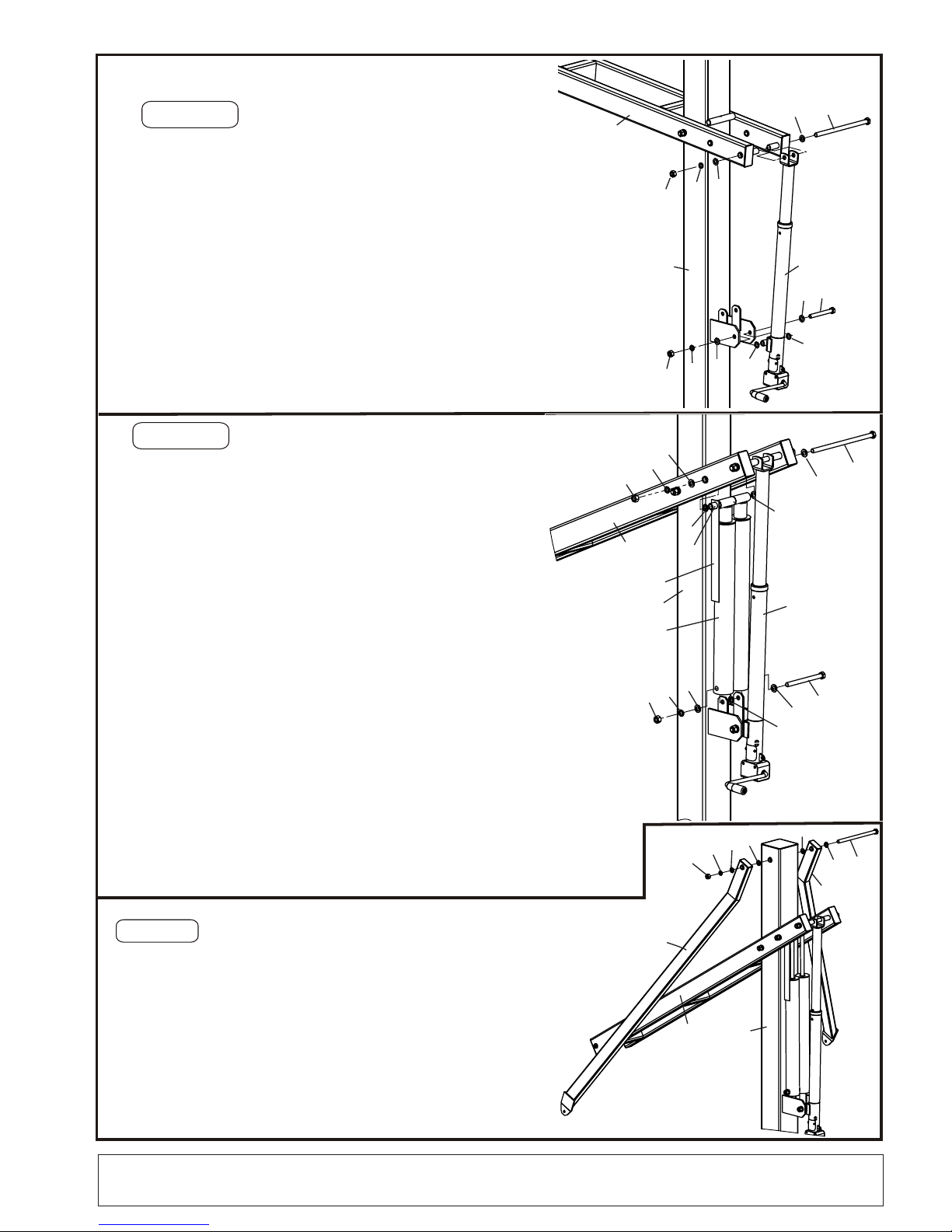
A. Slide the Actuator(B) to the last set of welded
tubes on the Main Extension Arm (F), Using a
Hex bolt M18X320MM (#5), two M18 Flat
Washers((#11), one Lock Washer (#14) and a Hex
Nut M18(#17) at the top. And using a
Hex Bolt M16x135mm (#9), two Washers for
M16 Bolt (#12), two Nylon washers (#2), and one
Hex nut for M16 bolt (#18) on bottom to tight
Note: make sure the Nylon washers go between
Actuator and Mounting Bracket.
the Actuator.
STEP 3
STEP 4
A.
B. Attach the bottom of Spring-assist Cartridges (C) to
the Main pole Bracket by using a
two Flat Washers M16 (#12), a Lock Washer M16 (#15)
a Nylon Washer M16 (#2) and a Hex Nut M16 (#18).
Note: Nylon washer goes between two Cartridges (C).
C. Remove and discard the White plastic spreader tube from the
Spring-Assist Cartridges(C).
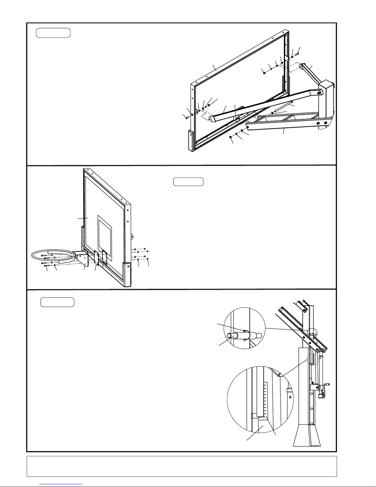
STEP 5
Slide Steel Sleeve (J) thru both tubes welded at the top end of
Spring-Assist Cartridge (C). Place the top of Spring-Assist between
Main extension (F), align the Steel Sleeve (J) with the second set of
welded tubes on the Main Extension Arm (F), place the Plastic rim
Height Indicator (K) beside the Spring-Assist Cartridge .
Slide one Washer M16 (#12) over one Hex Bolt M16x320mm
(#7), and slide this Bolt all the way thru Main Extension Arm (F), one
Nylon washer M16(#2), Steel Sleeve (J), Rim Height indicator
(K), another Nylon washer (#2) , and the other side of Main
Extension Arm (F). Secure it with one Flat Washer M16 (#12), one
Lock washer M16 (#15) and One Hex nut M16 (#18).
Do not over tighten this bolt because this is the pivot point.
Make sure the Plastic Rim Height Indicator(K) hang freely along side
of Spring-Assist Cartridge .
Nylon washer locates between Steel sleeves (J) and Main Extension
Arm (F).
9
12
2
2
12
15
18
B
A
5
11
11
14
17
F
7
12
12
15
18
2
J
2
K
A
F
B
C
8
12
12
15
18
2
Hex Bolt M16x185mm (#8),
6
12
2
G
G
2
12
15
18
FA
A. Attach the 2 Upper Extension Arms(G) to Main Post (A) with a Hex
Bolt M16x295mm (#6), two Flat Washers M16(#12), 2 Nylon washers
(#2), one Lock Washers M16 (#15) and one Hex Nut M16 (#18).
Do not tighten at this time.
9
WWW.RYVALHOOPS.COM
1 - 8 0 0 - 7 8 7 - 0 6 5 5

STEP 6
STEP 8
A. After everything is square, make sure all nuts on the
system have been tightened.
NOTE: But do not over tighten the Nuts, make sure the unit
can be adjusted up and down.
B. To apply the Rim Height Sticker(In the manual pack), first use
a tape measure to crank rim up to exactly 10’ from the playing
surface. Use a pencil to make a mark on the Spring-assist
Cartridge(C) where the bottom of the Rim Height Indicator(K)
stops. Then, peel and apply Rim Height Sticker to outside
of Spring-assist Cartridge(C) lining up the pencil mark with the
10’ mark on the Rim Height Sticker. See detail A.
C. Attach Post Pad and Gusset Pad to Main Post(A) as shown.
B.Mount the rim to the Mounting bracket on Backboard(H)
using the hardware supplied in rim box.
NOTE: Use a level to make sure rim is level side to side
before tightening nuts.
STEP 7
Attach the Backboard to Main Extension Arm(F)
by using a Hex Bolt m16x320mm (#7), two M16
Flat Washers(#12), two Nylon washers (#2), one
Lock washer M16 (#15), and one Hex nut M16
(#18).
Note: Nylon washers go between Main extension arm
Bracket (F) and Backboard mounting bracket.
connect Upper Extension Arms (G) to the
side of Backboard (H), using 2 Hex bolts
M12x35mm (#10), 4 Flat Washers M12 (#13),
2 Nylon washers M12 (#3), 2 Lock washers
M12(#16) and two Hex nuts M12 (#19).
Note: Put Nylon washers between backboard
plate and Upper extension connecting plate.
A.
B.
Remove the screws on Rim spring box cover, open
the Spring box.
Re-attach Spring box cover to the Rim with removed
screws.
A.
C.
F
GH
10
13 313 16 19
191613 3
13 10
G27
12
12
15
18
20 21 21 22
L
H
M
10
DETAIL A
DETAIL B
B
A
4
I
Rim Height
Sticker
C
Slide Safety Rod (I) thru the tube welded on the backside
of Main Post (A), align the holes each other and secure it
with one Lock Pin 6mm (#4). See detail B.
D.
10
WWW.RYVALHOOPS.COM 1 - 8 0 0 - 7 8 7 - 0 6 5 5

Ryval&Warranties&
Buyer agrees that products sold by Ryval hoops carry the following warranty.
Subject to proper installation and normal, intended use, all structural components of Coach Series tm, Phenom X Series tm, Wall
Mount Hoops are warranted to the original owner to be free of defects in materials and workmanship for the duration of ownership
(Limited Lifetime) by the original retail purchaser, subject to the limitations below. The Driveway Series tm will be covered by this
warranty for a period of 5 years. THIS LIMITED WARRANTY COVERAGE IS EXTENDED ONLY TO THE ORIGINAL RETAIL
PURCHASER AND TERMINATES IF THE ORIGINAL RETAIL PURCHASER OTHERWISE TRANSFERS OR SELLS THE
PRODUCT. This warranty is limited to a repair or replacement of the defective part. Product covered under this warranty will be
shipped at the customer’s expense. Ryval Hoops is not responsible for any expense associated with freight, or delivery and
installation of the warranted part(s). Ryval Hoops reserves the right to inspect all warranty claim parts for which a claim has been
made.
Any modification could damage the structural integrity of the equipment and voids all warranties.
Where listed as “Limited”, the warranties shall cover damage or failure that occurs during the course of normal or intended use of the
product. Normal or intended use shall be described as activity that is necessary for the participation in the sport for which the
equipment is designed. Not covered is damage caused by deliberate hanging, multiple player hanging, vandalism, non-basketball
activities or any other activity that could be regarded as abusive.
Actuator & Lift Assist Cylinders: Five-year limited warranty.
Padding Warranty: Multi-Purpose Backboard Edge Padding: One-year limited warranty. Custom fit & Wrap around Pole Padding &
Gusset Padding One-year limited warranty.
Net: One-year limited warranty
Not Covered By This Warranty
• Any Products subjected to abuse, negligence, improper installation, vandalism, acts of God, alteration of product or any
other events beyond the control of Ryval Hoops.
• Use in non-residential applications of glass backboards.
• Paint or rusted parts. If rust begins, sand rust & loose paint, primer & paint with a satin black. Touch-up kits are available.
• Deterioration of product due to time or wear and tear.
• Use in non-residential applications of Glass backboards.
Normal deterioration of products due to atmospheric conditions, weather, rust wear and tear (including paint), or other causes that do
not affect functional use are not covered by Ryval Hoops warranties. All warranties are valid only when product is used in the
intended application and when installed according to Ryval Hoops instructions. Warranty will be void if maintenance instructions in
the owner’s manual are not followed, including jack lubrication on a bi yearly basis. If you did not receive a owners/instruction
manual, please contact Ryval Hoops and one will be sent to you.
A limited lifetime warranty is effective for the duration of ownership by the original retail purchaser or 5 years after discontinuation of
the product by Ryval Hoops.
Warranty Claims: A copy of the original invoice must be presented to initiate warranty claim. A warranty claim form must be
completed and photos submitted for any item you wish to claim under warranty. If part to be warranty is requested, a “Return
Merchandise Authorization” (RMA) number will be required prior to shipping damaged Product by original retail Consumer Purchaser
with freight prepaid by consumer. If the purchase was made through a dealer, warranties do not cover dealer service charges, labor
charges, freight or travel expense associated with replacement, repair or removal or warranty item
This warranty is exclusive and expressly in lieu of all other warranties, expressed or implied, including warranties of merchantability
or fitness for use. Ryval Hoops does not assume, or authorize any person to assume for us, any other liability in connection with the
sale of our products. If Ryval Hoops cannot disclaim or exclude implied warranties under applicable law, then to the extent possible
any claims under such implied warranties shall expire or expiration or the applicable warranty period. Some states do not allow
limitations on how long an implied warranty lasts, so the above limitation may not apply to you, Ryval Hoops does not assume or
authorize any person to assume for us, any other liability in connection with the sale of our products. Ryval Hoops shall not be liable
for loss of use of the product or other consequential or incidental costs. Expenses or damages incurred by the consumer or any
other use.
To the maximum extent permitted by law, Ryval Hoops assumes no responsibility for incidental or consequential damages, which
may arise from the purchasers or use of our equipment. Some states don not allow the exclusion or limitations of incidental or
consequential damage, so the limitation or exclusion may not apply to you.
If any provision of this warranty is invalid, void or unenforceable in any instance or respect, the unenforceable provision will be
severed and reformed to affect the intent of this limited warranty to the maximum extent possible, and the remaining provisions shall
continue in full force and effect and shall be enforced to the full extent permitted by law.
Ryval Hoops reserves the right at any time to change product specifications or substitute similar components.
This warranty gives you specific rights and you may also have other rights, which vary from state to state.
Questions or Comments?
www.RyvalHoops.com
Email: info@ryvalhoops.com
Phone 800-787-0655

Table of contents