65
④
Rotate the Body by 180°using .
BEFORE USING THE DEVICE BEFORE USING THE DEVICE
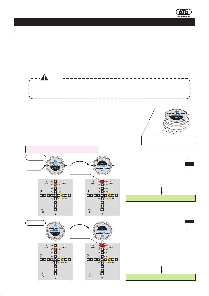
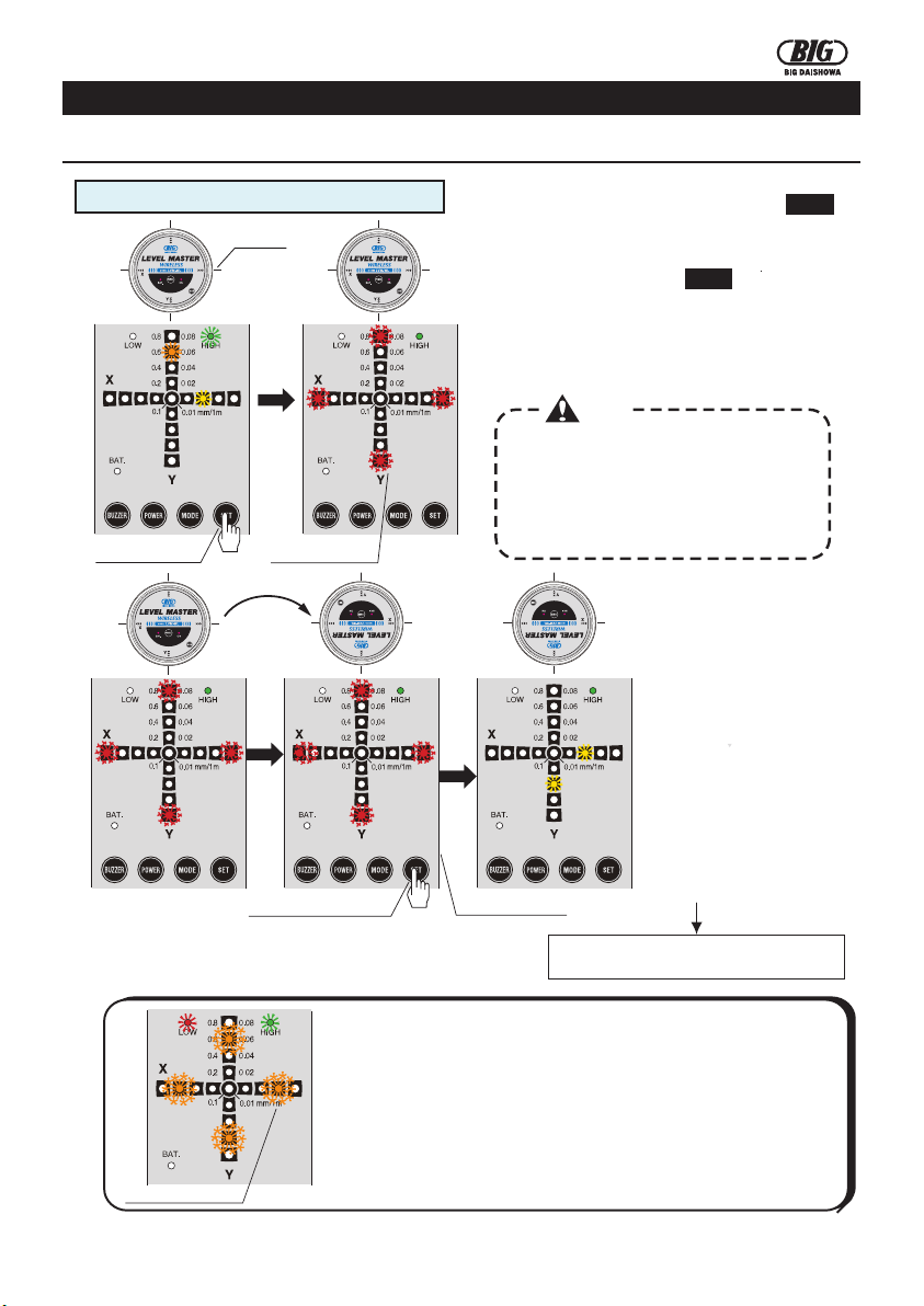
How to execute the zero adjustment in LOW mode
①Push the "SET" switch after 10 seconds.
The 4 external LEDs (red) start blinking.
When executing the "zero adjustment" in the
LOW mode, adjust the level in order to obtain
an inclination of the reference surface within
0.8 and then execute the "zero adjustment".
It is not possible to execute the "zero
adjustment" if the inclination exceeds 0.8.
Caution
marking marking
The 4 LEDs (red) start blinking The 4 LEDs (red) start blinking
Push the SET switch Push the SET switch
②Rotate the Body by 180°using
as reference the markings on the
reference surface.
Errors in the "zero adjustment"
may occur if the device is not
rotated correctly by 180°or if it is
not aligned with the markings.
③Push again the "SET" switch
after 10 seconds. The buzzer
will emit a "Beep" to notify
the completion of the
"zero adjustment".
Buzzer's sound "Beep" Buzzer's sound "Beep"
Push the SET switch Push the SET switch
Buzzer's sound
"Beep-beep-beep"
When the inclination of one of the axes is
adjusted within 0.1, the LED (blue) turns on
and the buzzer emits a sound [Beep, beep].
When the inclination of both axes is within
0.1, the LED (blue) turns on and the buzzer
emits a sound [Beep-beep-beep].
⑤Adjust the level of the reference surface in
order to obtain an inclination within 0.1 for
both axes.
Go to P6 →How to execute the zero adjustment in HIGH mode
Level adjustment of
the reference surface Continuous LED (blue)
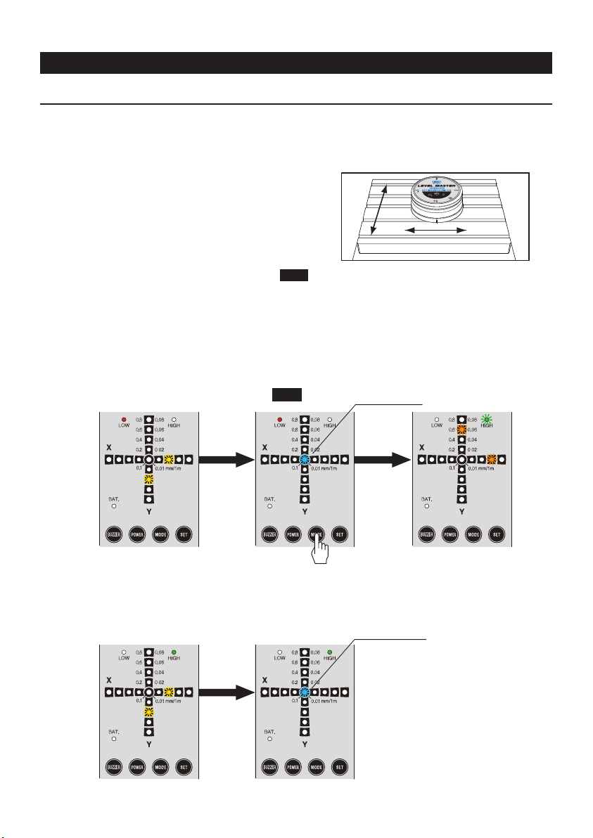
How to execute the zero adjustment in HIGH mode
③Push the "SET" switch after 10 seconds.
The 4 external LEDs (red) start blinking.
Execute the levelling operation.
③Push again the "SET"
switch after 10 seconds.
The buzzer will emit a
"Beep" to notify the
completion of the
"zero adjustment".
④Rotate the device by180°
using asreference the
markings on the reference
surface.
Errors in the "zero
adjustment" may occur if
the device is not rotated
correctly by 180°
or if it is not aligned with the
markings.
The 4 LEDs (orange) start blinking
When executing the "zero adjustment" in
the HIGH mode, adjust the level in order to
obtain an inclination of the reference
surface within 0.08 and then execute the
"zero adjustment".
It is not possible to execute the "zero
adjustment" if the inclination exceeds 0.08.
Caution
In case of executing the "zero adjustment" in the LOW mode:
◆When the level exceeds 0.8
In case of executing the "zero adjustment" in the HIGH mode:
◆ When the level exceeds 0.08
In case of pushing the "SET" switch, turning the device by 180°
and pushing again the "SET" switch in the above situations, the 4
orange LEDs of 0.6 (for the LOW mode) / 0.06 (for the HIGH
mode) blink 4 times and at the same time the buzzer emit a
"be-be-be-be" sound to notify that it is not possible to execute the
setting operation.
①Push the MODE switch to change to the HIGH
mode.
②The levelling value of the X and Y axes is within
0.08 after switching to the HIGH mode.
T
u
r
n
b
y
1
8
0
°
T
u
r
n
b
y
1
8
0
°
T
u
r
n
b
y
1
8
0
°