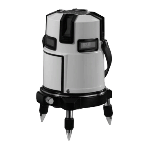
Big Daishowa LVM-01 User manual

取扱説明書
精密電子水準器
INDEX
このたびは、 レベルマスタ−(LVM-01)を御採用頂きまして有難うございます。測定器としてお取扱いの上、
末永く作業にお役立てください。なおご使用前に必ず本書をお読みいただき、ご使用される方がいつでも見ること
が できる場 所 に 必 ず 保 管してくださいますようお 願 いします 。
本商品は、弊社の厳密なる品質および精度検査に合格した事を証明致します。
Thank you for using Level Master (LVM-01). Please handle it as a measuring instrument
and utilize it for long time. Please be sure to read this manual before using the device and
also keep it in a location where all the operators may consult it in case of necessity.
We certify this product has passed our rigorous inspections of quality and accuracy.
レベルマスターLVM-01
OPERATION MANUAL
1.仕 様
2.各部の名称および機能
3.バッテリ−のセット方法
4.使用前の準備
4-1.環境設定
4-2.ゼロ調整の実施
5.使用方法
5-1.水平レベル作業
5-2.ブザ−音有無の切替
5-3.初期値へのリセット
6.使用上の注意
P1
P1〜P2
P2
P3
P3〜P6
P7〜P8
P8
P8
P9
1. SPECIFICATIONS
2.
NAMES OF PARTS AND FUNCTIONS
3.
HOW TO INSTALL THE BATTERIES
4. BEFORE USING THE DEVICE
4-1. Environmental settings
4-2.
How to execute the zero adjustment
5. OPERATIONS
5-1. Levelling operation
5-2. How to turn on/off the buzzer
5-3.
How to reset the device to its default values
6. SAFETY NOTES
7. EMC INFORMATION
P11
P11
-
P12
P12
P13
P13
-
P16
P17
-
P18
P18
P18
P19
P20
Caution
ご注意
C
E
R
T
I
F
I
E
D
M
A
N
A
G
E
M
E
N
T
S
Y
S
T
E
M
ISO
9001
JQA-QM3913
FA事業部
■本 社
東大阪市西石切町3丁目3-39 〒579-8013
TEL.072(982)2312(代)FAX.072(980)2231
<ホームページ>www.big-daishowa.co.jp
高品位合衆国
LEVEL MASTER LVM-01
Precision Electronic Level
No.1218

1.仕様
仕様・各部の名称および機能
● LED 表 示
モ−ド
LED()点滅:0.08mm超え/1mの傾き
LED()点灯:0.08mm以下/1mの傾き
LED()点灯:0.06mm以下/1mの傾き
LED()点灯:0.04mm以下/1mの傾き
LED()点灯:0.02mm以下/1mの傾き
LED()点灯:0.01mm以下/1mの傾き
HIGH
モ−ド
LED()点滅:0.8mm超え/1mの傾き
LED()点灯:0.8mm以下/1mの傾き
LED()点灯:0.6mm以下/1mの傾き
LED()点灯:0.4mm以下/1mの傾き
LED()点灯:0.2mm以下/1mの傾き
LED()点灯:0.1mm以下/1mの傾き
LOW
型式
最小読み取り値
電源
オ−ト電源OFF
使用温度範囲
電池寿命
寸法
質量
0.01mm/1m
アルカリ乾電池:LR03(単4形)×4P
電源投入後30分後に電源OFF
0℃〜40℃(推奨20℃±5℃)
連 続50時 間
φ109×H56
995g
仕様
LV M - 01
付属品アルカリ乾電池:LR03(単4形)×4P
取扱説明書、検査成績表
仕様・各部の名称および機能
2.各部の名称および機能
①電源スイッチ
POWERマ−クを押すと電源ONに入りレベル表
示LEDが点灯し、レベル作業を行なう事ができ
ます。
② モ −ド ス イ ッ チ
MODEマ−クを押す事によりレベル精度を切り替
える事ができます。電源ON時はHIGHモ−ドに
設定されています。
③ セ ット ス イ ッ チ
『ゼロ調整』を行なうためのセット用スイッチです。
⑥レベル表示LED(センタ−位置)
レベル状態がセンタ−位置の時にLED(青)が点灯
します。
の場合は傾斜が0.1mm以下/1m
の場合は傾斜が0.01mm以下/1m
⑦ モ −ド 表 示 LED
モ−ド時にLED(赤)が点灯します。
⑧ モ −ド 表 示 LED
モ−ド時にLED(緑)が点灯します。
⑨バッテリ−アラ−ムLED
バッテリ−の電圧が4V以下の場合にLED(橙)が
点滅しバッテリ−の交換をお知らせします。
⑩ブザ−
レベル状態がセンタ−位置の場合に⑥のレベル
表示LED(青)点灯と本ブザ−にて
お知らせします。
⑬ 合 マ−ク
X・Y軸の方向を決定する際に使用します。
⑮ バッテリ−ボックス
バッテリ−(LR03:単4形×4P)をセットする場所です。
⑭ブザ−音
センタ−位置のお知らせ音の有無を切替えます。
⑪本体ベ−ス部
⑫本体ケ−ス部
ON OFF
HIGH LOW
④レベル表示LED(X軸)
レベル状態を表示します。
の場合は傾斜が0.8mm〜0.1mm以下/1m
の場合は傾斜が0.08mm〜0.01mm以下/1m
HIGH
LOW
LOW
⑤レベル表示LED(Y軸)
レベル状態を表示します。
の場合は傾斜が0.8mm〜0.1mm以下/1m
の場合は傾斜が0.08mm〜0.01mm以下/1m
HIGH
LOW
HIGH
LOW
仕様・各部の名称および機能
3 . バ ッ テ リ − の セ ッ ト 方 法
②電池ボックスの底部に明記されているように、付属のアル
カリ乾電池(LR03:単4形)4本を右図のようにセットしてく
ださい。
③電池セット後、カバ−の凸部を電池ボックスの凹部に差し
込みカバ−を取り付けてください。取り付け後、取付ボル
トにてカバ−を固定してください。
①バッテリ−ボックスカバ−の取付ボルトを緩めてください。
バッテリ−ボックス
バッテリ−
LR03(単4形)×4P
カバ−
カバ−凸部
取付ボルト
バッテリーの極性は、必ずご確認ください。極性を
逆さに挿入された場合、動作しないばかりか本器の
内部電気回路を破損させご使用できなくなる事があ
ります。
ご注意
HIGH
ON OFF 切 替 ス イ ッ チ
①②
③
④⑤
⑥⑦ ⑧
⑨
⑩
⑪
⑫
⑬⑬
⑭ ⑮
1 2
※本製品は、EMC規格:EN61326-1に適合しております。

4.使用前の準備
4-1.環境設定
4-2.ゼロ調整の実施
使用前の準備
保管場所と使用場所の温度差がある場合には、使用される場所で一定の時間放置し、ならし環境(温湿
度)設定を行ってください。
レベルマスタ−の電源を入れた時に、使用環境・測定基準面の状態により必ずしも、水平位
置が0位置(青LED点灯)が表示されるわけではありません。毎回、使用環境に応じた
ゼロ基準の設定を『ゼロ調整』にて行ってください。
③POWERスイッチを押し、電源をONにしてください。
④下記手順にて水平レベルの確認およびゼロ調整を行ってください。
②本器の本体ベ−ス部の合マ−クを基準に基準面XY方向4カ所を
マ−キングしてください
4カ 所 に
マ−キング
①基準面に本器を置いてください。設置の際には、本器の底面に付
着している油分・ゴミおよび精密定盤の基準面位置のキズや付着
している油分・ゴミ等を取り除いてください。
(例:温度差10℃の場合15分〜20分)
HIGHモ−ド時の水平レベルの確認
P6→HIGHモ−ド時のゼロ調整へ
180°反転
②180°反転後、XY軸ともに水平レベル
0.08以内である。
①電源ON後、XY軸ともに水平レベルが
0.08以内である。
P4→LOWモ−ド時の水平レベル確認へ
②180°反転後、XY軸のどちらかが水平
レベル0.08を超えている場合。
LED(赤)点滅
①電源ON後、XY軸ともに水平レベルが
0.08以内である。
ケIス1
ケIス2
180°反転
LED(赤)点灯
LED(赤)点滅
ご注意
使用前の準備
LOWモ−ド時の水平レベルの確認
P4→LOWモ−ド時の水平レベル確認へ
①電源ON後、XY軸のどちらかが水平レベル
0.08を超えている場合。LED(赤)点滅
ケIス3
LED(赤)点滅
LED(赤)点滅
180°反転
ケIス2
LED(赤)点滅
P5→LOWモ−ド時のゼロ調整へ
③180°反転後、XY軸ともに水平レベル
0.8以内である。
② モード投入後、XY軸ともに水平
レベルが0.8以内である。
180°反転
P5→LOWモ−ド時のゼロ調整へ
ケIス1
LED(赤)点灯
LOW
LOW
① モードへ切替えてください。
② モード投入後、XY軸ともに水平
レベルが0.8以内である。
LOW
LOW
① モードへ切替えてください。
LOW
LOW
① モードへ切替えてください。
③180°反転後、XY軸のどちらかが水平
レベルが0.8を超えている場合
ケIス3
② モード投入後、XY軸のどちらか
が水平レベルが0.8を超えている場合。
LED(赤)点滅
④XY軸ともに水平レベルが0.8以内に
なるように基準面の水平レベルの調整
を行ってください。
P5→LOWモ−ド時のゼロ調整へ
③XY軸ともに水平レベルが0.8以内に
なるように基準面の水平レベルの調整
を行ってください。
3 4

使用前の準備 使用前の準備
LOWモ−ド時のゼロ調整 HIGHモ−ド時のゼロ調整
①10秒後、『SET』スイッチを押してくだ
さい。
外側のLED(赤)4カ所が点滅します。
①10秒後、『SET』スイッチを押してくだ
さい。
外側のLED(赤)4カ所が点滅します。
③10秒後、再度『SET』スイッチを押す
とブザー音がピ−と鳴り『ゼロ調整』
が完了です。
②基準面のマ−キング位置を基準に本器を
180°反転させてください。
ブザ−音ピ−
マ−キング位置からの左右のズレや正確
に180°反転していない場合は、『ゼロ
調整』に誤差が生じます。
180°反転
マ−キング
SETスイッチを押す
LOWモ−ドで『ゼロ調整』を行う場合
◆水平レベルが0.8を超えた状態
HIGHモ−ドで『ゼロ調整』を行う場合
◆水平レベルが0.08を超えた状態
LED(青)点灯
ブザ−音
『ピッピッピ』
XY軸のうち1軸が傾き0.1以下に調整された場
合には、LED(青)が点灯し『ピッ、ピッ』とブ
ザー音が鳴ります。両軸が0.1以下の傾きにな
った場合はLED(青)が点灯し『ピッピッピ』と
鳴ります。
基準面の水平レベル調整
④基準面の水平レベルをXY軸ともに0.1以下
に水平レベル調整を行ってください。
P6→HIGHモ−ド時のゼロ調整へ
水平レベル作業を行ってください。
③10秒後、再度『SET』スイッチを押す
とブザー音がピ−と鳴り『ゼロ調整』
が完了です。
②基準面のマ−キング位置を基準に本器を
180°反転させてください。
ブザ−音ピ−
マ−キング位置からの左右のズレや正確
に180°反転していない場合は、『ゼロ
調整』に誤差が生じます。
180°反転
マ−キング
LED(橙)4カ所点滅
LOWモ−ドでの『ゼロ調整』を行
う場合は、基準面の傾きを0.8以内
に水平レベル調整を行い『ゼロ調
整』を行ってください。
水平レベルが0.8を超えると『ゼロ
調整』が出来ません。
ご注意
HIGHモ−ドでの『ゼロ調整』を行
う場合は、基準面の傾きを0.08以
内に水平レベル調整を行い『ゼロ調
整』を行ってください。
水平レベルが0.08を超えると『ゼ
ロ調整』が出来ません。
ご注意
『SET』スイッチを押し、180°反転させ再度『SET』ボタン
を押した時、上記状態の場合0.6(LOWモード時)・0.06(HIGH
モード時)の橙色LED(4カ所)が4回点滅し、同時にブザ−が
ピピピピと鳴り、セット出来ない事をお知らせします。
SETスイッチを押す
LED(赤)4カ所点滅
SETスイッチを押す LED(赤)4カ所点滅
SETスイッチを押す
5 6

使用方法
5.使用方法
①本器の底面および機械テ−ブル面の傷・打痕および油分・ゴミ等を取り除いてください。
②基準面にX・Y軸が真直ぐになるよう、丁寧に置
いてください。
X軸
Y軸
③POWERスイッチを押し、電源をONにしてください。
LED(赤)点滅
電源ON時
LED(赤)が点灯している場合や他のLEDが点灯している場合は、傾きが0.08以下です。 モードの
状態で⑦の作業から行ってください。
LED(青)点灯 ブザ−音にて
お知らせ
⑤モードでセンター位置のLED(青)が点灯するようにレベル調整を行ってください。LED(青)
が点灯時は、傾きは0.1以下です。
XY軸のうち1軸が傾き0.1以下に調整された場合には、LED(青)が点灯し『ピッ、ピッ』とブザー
音が鳴ります。両軸が0.1以下の傾きになった場合はLED(青)が点灯し『ピッピッピ』と鳴ります。
モ−ド切替
④電源ON時はモード(傾き:0.01mm〜0.10mm以内)に設定されていますので、LED(赤)
が0.08位置で点滅している場合は、傾きが0.1以上の傾きですので、MODE切替スイッチでLOW
モード(0.1mm〜1mm以内)に切り替えてください。
5-1.水平レベル作業
SETスイッチを押す
OFF→ON
使用方法
LED(青)点灯
⑥MODE切替スイッチ モードに切替え
てください。
⑦センタ−位置のLED(青)が点灯するようにレベル
調整を行ってください。
XY軸のうち1軸が傾き0.01以下に調整された
場合には、LED(青)が点灯し『ピッ、ピッ』とブ
ザー音が鳴ります。両軸が0.01以下の傾きにな
った場合はLED(青)が点灯し『ピッピッピッ』と
鳴ります。
ブザ−音にて
お知らせ
モ−ド時に傾きが0.01以下の場合および
モ−ド時に傾きが0.1以下の場合にLED
(青)点灯とブザ−音にてお知らせしますがブザ−
音の要・不要の切替えについては、本器底部の
ブザ−音切替えスイッチにて行う事ができます。
5-2.ブザ−音有無の切替
5-3.初期値へのリセット
初期値(納入時の状態)に戻したい時は、『SET』
スイッチを押しながら電源をOFFからONにしま
す。内部データがクリアーされます。
HIGH
HIGH
HIGH
HIGH
LOW
LOW
LOW
7 8

使用方法
5.使用方法
①本器の底面および機械テ−ブル面の傷・打痕および油分・ゴミ等を取り除いてください。
②基準面にX・Y軸が真直ぐになるよう、丁寧に置
いてください。
X軸
Y軸
③POWERスイッチを押し、電源をONにしてください。
LED(赤)点滅
電源ON時
LED(赤)が点灯している場合や他のLEDが点灯している場合は、傾きが0.08以下です。 モードの
状態で⑦の作業から行ってください。
LED(青)点灯 ブザ−音にて
お知らせ
⑤モードでセンター位置のLED(青)が点灯するようにレベル調整を行ってください。LED(青)
が点灯時は、傾きは0.1以下です。
XY軸のうち1軸が傾き0.1以下に調整された場合には、LED(青)が点灯し『ピッ、ピッ』とブザー
音が鳴ります。両軸が0.1以下の傾きになった場合はLED(青)が点灯し『ピッピッピ』と鳴ります。
モ−ド切替
④電源ON時はモード(傾き:0.01mm〜0.10mm以内)に設定されていますので、LED(赤)
が0.08位置で点滅している場合は、傾きが0.1以上の傾きですので、MODE切替スイッチでLOW
モード(0.1mm〜1mm以内)に切り替えてください。
5-1.水平レベル作業
SETスイッチを押す
OFF→ON
使用方法
LED(青)点灯
⑥MODE切替スイッチ モードに切替え
てください。
⑦センタ−位置のLED(青)が点灯するようにレベル
調整を行ってください。
XY軸のうち1軸が傾き0.01以下に調整された
場合には、LED(青)が点灯し『ピッ、ピッ』とブ
ザー音が鳴ります。両軸が0.01以下の傾きにな
った場合はLED(青)が点灯し『ピッピッピッ』と
鳴ります。
ブザ−音にて
お知らせ
モ−ド時に傾きが0.01以下の場合および
モ−ド時に傾きが0.1以下の場合にLED
(青)点灯とブザ−音にてお知らせしますがブザ−
音の要・不要の切替えについては、本器底部の
ブザ−音切替えスイッチにて行う事ができます。
5-2.ブザ−音有無の切替
5-3.初期値へのリセット
初期値(納入時の状態)に戻したい時は、『SET』
スイッチを押しながら電源をOFFからONにしま
す。内部データがクリアーされます。
HIGH
HIGH
HIGH
HIGH
LOW
LOW
LOW
7 8

使用上の注意
6.使用上の注意
・絶対水平0.01以下を確保するために、定盤表面は平面度の良いものをご使用ください。
・レベルマスタ−の直径はφ109mmですので、2μのゴミが噛んだだけでも1mに対し0.018mmの
狂いが生じます。
・本器は精密機器です。落としたり、衝撃を与えたりしないでください。また、ご使用後は必ず本器の
底面に防錆油を塗布し専用収納ケースに入れ、保管してください。
・保管時は、0℃〜40℃の保管環境温度にて保管してください。
・本器は精密機器のため、ク−ラントをかけたりしないでください。また、ご使用後は機械テ−ブル、定盤、
組立治具上などに放置しないでください。
・本器は精密機器のため、お客様の方での分解・改造を行わないでください。性能や寿命を劣化させる
原因にもなり保証できなくなります。
・長期間ご使用にならない場合は、バッテリ−を取り外してください。
・精度が狂ったり、不具合が発生した場合はご使用を中止し、ご購入先を通じて へ修理、点 検 に お
出しください。
9 10
MEMO

1. SPECIFICATIONS
SPECIFICATIONS - NAMES OF PARTS AND FUNCTIONS
2. NAMES OF PARTS AND FUNCTIONS
●LED indicators
Blinking LED( ):Inclination exceeding 0.08mm/1m
Continuous LED( ):Inclination of 0.08mm/1m or less
Continuous LED( ):Inclination of 0.06mm/1m or less
Continuous LED( ):Inclination of 0.04mm or less
Continuous LED( ):Inclination of 0.02mm/1m or less
Continuous LED( ):Inclination of 0.01mm/1m or less
mode
HIGH
mode
Blinking LED( ):Inclination exceeding 0.8mm/1m
Continuous LED( ): Inclination of 0.8mm/1m or less
Continuous LED( ): Inclination of 0.6mm/1m or less
Continuous LED( ):Inclination of 0.4mm/1m or less
Continuous LED( ):Inclination of 0.2mm/1m or less
Continuous LED( ):Inclination of 0.1mm/1m or less
LOW
Specifications
Model
Minimum readable value
Power supply
Auto-power OFF
Operating temperature
Battery life
Dimensions
Weight
LVM-01
0.01mm/1m
Alkaline dry battery: LR03 (AAA) x4
The power turns OFF automatically after 30 minutes.
0°C
-
40°C (Recommended temperature 20°C ±5°C)
50 continuous hours
ø109 x H56
995g
Included items Alkaline dry battery: LR03 (AAA) x4,
Operation manual and inspection report card
①POWER switch ON OFF
Push the POWER switch to turn ON the power
and the LED level indicators. It is now possible
to execute the levelling operation.
②MODE switch HIGH LOW
Push the MODE switch to change the precision
level. The "HIGH" mode is selected when turning
ON the device.
③SET switch
This switch is used to execute the zeroadjustment.
⑥LED level indicator (Central position)
The LED (blue) turns on when the level status
reaches the central position.
The inclination is 0.1mm/1m or less in case of the
LOW mode.
The inclination is 0.01mm/1m or less in case of the
HIGH mode.
⑦Mode LED
The LED (red) turns on when the LOW mode
is selected.
⑧
Mode LED
The LED (green) turns on when the
HIGH
mode
is selected.
⑨Battery alarm LED
If the voltage of the batteries decreases to 4V or
less, the LED(orange) blinks notifying the necessity
of replacing the batteries.
⑩Buzzer
The buzzer emits a sound and the LED (blue)
described on point ⑥turns on when the level
status reaches the central position.
⑬Line markers
They are used for determining the direction of the
X and Y axes.
⑮Batteries box
It is the location where the batteries are installed
(LR03: AAA x4).
⑪Base
⑫Body case
④LED level indicators (X-axis)
They indicate the level status.
The inclination is between 0.8mm/1m and
0.1mm/1m in case of the LOW mode.
The inclination is between 0.08mm/1m and
0.01mm/1m in case of the HIGH mode.
⑤LED level indicators (Y-axis)
They indicate the level status.
The inclination is between 0.8mm/1m and
0.1mm/1m in case of the LOW mode.
The inclination is between 0.08mm/1m
and 0.01mm/1m in case of the HIGH mode.
3. HOW TO INSTALL THE BATTERIES
②Insert the 4 batteries included (LR03: AAA) in the base of the
batteries box as indicated on the figure on the right.
③After have installed the batteries, insert the projecting part of the
cover into the recess of the batteries box. Then, secure the cover
by tightening the screw.
①Loose the screw of the cover of the batteries box.
Batteries box
Batteries
LR03 (AAA) x4
Cover
Projecting part of the cover Screw
Always check the polarity of the batteries. If the batteries
are inserted with the polarity inverted, the device may not
work and the internal electric circuit may get damaged
making the device not utilizable.
Caution
⑭Buzzer sound ON OFF switch
This switch is used for turning on/off the buzzer.
①②
③
④⑤
⑥⑦ ⑧
⑨
⑩
⑪
⑫
⑬⑬
⑭ ⑮
11 12
HOW TO INSTALL THE BATTERIES
This product complies with the EMC standard EN 61326-1.

Caution
4. BEFORE USING THE DEVICE
4-1. Environmental settings
4-2. How to execute the zero adjustment
BEFORE USING THE DEVICE
If there is a difference in the temperature between the storage location and the utilization location,
leave the device for a certain amount of time in the utilization location to perform the average
environmental settings (temperature, humidity).
When the Level Master is turned on, depending on the utilization environment and on the status
of the reference surface measured, the level position may not be always the "0" position
(continuous blue LED). Execute every time the reference settings by means of zero adjustment
in accord with the utilization environment.
③Push the POWER switch to turn ON the power.
④Execute the zero adjustment and the levelling checks following
the proceduresbelow.
②Use as reference the line markers on the base of the device and
mark 4 points in the X and Y directions on the reference surface.4 markings
①Position the device on the reference surface. When placing the
device, remove oil and dirt from its base and also remove notches,
oil and dirt from the reference surface of the precision plate.
(Example: If the difference in the temperature is 10°C, leave the device for 15
-
20 minutes.)
How to check the levelling value in HIGH mode
Go to P6 →How to execute the zeroadjustment in HIGH mode
Turn by 180°
②The levelling value of both axes is within
0.08 after turning the device by 180°.
①The levelling value of the X and Y axes
is within 0.08 after turning ON the power.
Go to P4 →How to check the levelling value in LOW mode
②The levelling value of one of the axes
exceeds 0.08 after turning the device by
180°The LED (red) is blinking.
①The levelling value of the X and Y axes
is within 0.08 after turning ON the power.
Case1
Case2
Turn by 180°
Continuous LED (red)
Blinking LED (red)
How to check the levelling value in LOW mode
Go to P4 →How to check the levelling value in LOW mode
①The levelling value of one of the axes exceeds
0.08 after turning ON the power. The LED (red)
is blinking.
Case 3
Blinking LED (red)
Blinking LED (red)
Turn by 180°
Case 2
Blinking LED (red)
③The levelling value of both axes is
within 0.8 after turning the device by
180°.
②The levelling value of the X and Y axes
is within 0.8 after switching to the LOW
mode.
Turn by 180°
Go to P5 →How to execute the zero adjustment in LOW mode
Go to P5 →How to execute the zero adjustment in LOW mode
Case 1
Continuous LED (red)
①Switch to LOW mode.
③The levelling value of one of the axes
exceeds 0.8 after turning the device by
180°.
②The levelling value of the X and Y axes
is within 0.8 after switching to the LOW
mode.
①Switch to LOW mode.
Case 3
②The levelling value of one of the axes
exceeds 0.8 after switching to the LOW
mode. The LED (red) is blinking.
①Switch to LOW mode.
④Adjust the level of the reference
surface in order to obtain a levelling
value within 0.8 for both axes.
Go to P5 →How to execute the zero adjustment in LOW mode
③Adjust the level of the reference
surface in order to obtain a levelling
value within 0.8 for both axes.
13 14
BEFORE USING THE DEVICE

When executing the "zero adjustment" in
the LOW mode, adjust the level in order to
obtain an inclination of the reference
surface within 0.8 and then execute the
"zero adjustment".
It is not possible to execute the "zero
adjustment" if the inclination exceeds 0.8.
Caution
BEFORE USING THE DEVICE BEFORE USING THE DEVICE
How to execute the zero adjustment in LOW mode How to execute the zero adjustment in HIGH mode
①Push the "SET" switch after 10 seconds.
The 4 external LEDs (red) start blinking.
①Push the "SET" switch after 10 seconds.
The 4 external LEDs (red) start blinking.
③Push again the "SET" switch after 10
seconds. The buzzer will emit a "Beep"
to notify the completion of the
"zero adjustment".
②Rotate the device by 180°using as
reference the markings on the reference
surface.
Buzzer's sound "Beep"
Errors in the "zero adjustment" may occur if
the device is not rotated correctly by
180°or if it is not aligned with the markings.
Turn by 180°
Marking
Push the SET switch
In case of executing the "zero adjustment" in the LOW mode:
◆When the level exceeds 0.8
In case of executing the "zero adjustment" in the HIGH mode:
◆When the level exceeds 0.08
Continuous LED (blue)
Buzzer's sound
"Beep-beep-beep"
When the inclination of one of the axes is
adjusted within 0.1, the LED (blue) turns on
and the buzzer emits a sound [Beep, beep].
When the inclination of both axes is within
0.1, the LED (blue) turns on and the buzzer
emits a sound [Beep-beep-beep].
Level adjustment of
the reference surface
④Adjust the level of the reference surface in
order to obtain an inclination within 0.1 for
both axes.
Go to P6 →How to execute the zero adjustment in HIGH mode
Execute the levelling operation.
③Push again the "SET" switch after 10
seconds. The buzzer will emit a "Beep" to
notify the completion of the
"zero adjustment".
②Rotate the device by 180°using as
reference the markings on the reference
surface.
Buzzer's sound "Beep"
Errors in the "zero adjustment" may occur if
the device is not rotated correctly by 180°
or if it is not aligned with the markings.
Turn by 180°
Marking
The 4 LEDs (orange)
start blinking
When executing the "zero adjustment" in
the HIGH mode, adjust the level in order to
obtain an inclination of the reference
surface within 0.08 and then execute the
"zero adjustment".
It is not possible to execute the "zero
adjustment" if the inclination exceeds 0.08.
In case of pushing the "SET" switch, turning the device by 180°
and pushing again the "SET" switch in the above situations, the 4
orange LEDs of 0.6 (for the LOW mode) / 0.06 (for the HIGH
mode) blink 4 times and at the same time the buzzer emit a
"be-be-be-be" sound to notify that it is not possible to execute the
setting operation.
Push the SET switch
The 4 LEDs (red)
start blinking
The 4 LEDs (red)
start blinking
Push the SET switch Push the SET switch
Caution
15 16

When executing the "zero adjustment" in
the LOW mode, adjust the level in order to
obtain an inclination of the reference
surface within 0.8 and then execute the
"zero adjustment".
It is not possible to execute the "zero
adjustment" if the inclination exceeds 0.8.
Caution
BEFORE USING THE DEVICE BEFORE USING THE DEVICE
How to execute the zero adjustment in LOW mode How to execute the zero adjustment in HIGH mode
①Push the "SET" switch after 10 seconds.
The 4 external LEDs (red) start blinking.
①Push the "SET" switch after 10 seconds.
The 4 external LEDs (red) start blinking.
③Push again the "SET" switch after 10
seconds. The buzzer will emit a "Beep"
to notify the completion of the
"zero adjustment".
②Rotate the device by 180°using as
reference the markings on the reference
surface.
Buzzer's sound "Beep"
Errors in the "zero adjustment" may occur if
the device is not rotated correctly by
180°or if it is not aligned with the markings.
Turn by 180°
Marking
Push the SET switch
In case of executing the "zero adjustment" in the LOW mode:
◆When the level exceeds 0.8
In case of executing the "zero adjustment" in the HIGH mode:
◆When the level exceeds 0.08
Continuous LED (blue)
Buzzer's sound
"Beep-beep-beep"
When the inclination of one of the axes is
adjusted within 0.1, the LED (blue) turns on
and the buzzer emits a sound [Beep, beep].
When the inclination of both axes is within
0.1, the LED (blue) turns on and the buzzer
emits a sound [Beep-beep-beep].
Level adjustment of
the reference surface
④Adjust the level of the reference surface in
order to obtain an inclination within 0.1 for
both axes.
Go to P6 →How to execute the zero adjustment in HIGH mode
Execute the levelling operation.
③Push again the "SET" switch after 10
seconds. The buzzer will emit a "Beep" to
notify the completion of the
"zero adjustment".
②Rotate the device by 180°using as
reference the markings on the reference
surface.
Buzzer's sound "Beep"
Errors in the "zero adjustment" may occur if
the device is not rotated correctly by 180°
or if it is not aligned with the markings.
Turn by 180°
Marking
The 4 LEDs (orange)
start blinking
When executing the "zero adjustment" in
the HIGH mode, adjust the level in order to
obtain an inclination of the reference
surface within 0.08 and then execute the
"zero adjustment".
It is not possible to execute the "zero
adjustment" if the inclination exceeds 0.08.
In case of pushing the "SET" switch, turning the device by 180°
and pushing again the "SET" switch in the above situations, the 4
orange LEDs of 0.6 (for the LOW mode) / 0.06 (for the HIGH
mode) blink 4 times and at the same time the buzzer emit a
"be-be-be-be" sound to notify that it is not possible to execute the
setting operation.
Push the SET switch
The 4 LEDs (red)
start blinking
The 4 LEDs (red)
start blinking
Push the SET switch Push the SET switch
Caution
15 16

OPERATIONS
5. OPERATIONS
①Remove oil, dirt, notches and marks from the machine table's surface and from the base of the device.
②Place the device carefully on the reference surface
parallel to the X and Y axes.
X-axis
Y-axis
③Push the POWER switch to turn ON the power.
The LED (red) starts blinking
Continuous LED (blue) Audio notification
⑤Adjust the level in order to turn on the LED (blue) of the central position in the LOW mode. When the
LED (blue) turns on, the inclination is within 0.1.
When the inclination of one of the axes is adjusted within 0.1, the LED (blue) turns on and the buzzer
emits a sound [Beep, beep].
When the inclination of both axes is within 0.1, the LED (blue) turns on and the buzzer emits a
sound [Beep-beep-beep].
The power is turned ON Changing the mode
If the LED (red) or other LEDs turn on, the inclination is within 0.08. If this situation occurs when
the HIGH mode is selected, execute the operation of point ⑦.
④The HIGH mode (inclination between 0.01mm and 0.10mm) is set when the power is turned ON.
If the LED (red) in the 0.08 position blinks, the inclination exceeds 0.1. Use the MODE switch to
change to the LOW mode (inclination between 0.1mm and 1mm).
5-1. Levelling operation
Push the SET switch
OFF→ON
Continuous LED (blue)
⑥Push the MODE switch to change to the HIGH
mode.
⑦Adjust the level in order to turn on the LED (blue)
of the central position.
When the inclination of one of the axes is
adjusted within 0.01, the LED (blue) turns on and
the buzzer emits a sound [Beep, beep]. When the
inclination of both axes is within 0.01, the LED
(blue) turns on and the buzzer emits a sound
[Beep-beep-beep].
Audio notification
When the inclination is within 0.01( HIGH mode)
or within 0.1 (LOW mode), the LED (blue) turns
on and the buzzer emits a sound. It is possible to
turn on/off the buzzer's sound by using the
switch on the base of the device.
5-2. How to turn on / off the buzzer
5-3.
How to reset the device to its default values
To reset the device to its default values (delivery
condition), push the "SET" switch while turning ON
the power. The internal data are cleared.
17 18
OPERATIONS

OPERATIONS
5. OPERATIONS
①Remove oil, dirt, notches and marks from the machine table's surface and from the base of the device.
②Place the device carefully on the reference surface
parallel to the X and Y axes.
X-axis
Y-axis
③Push the POWER switch to turn ON the power.
The LED (red) starts blinking
Continuous LED (blue) Audio notification
⑤Adjust the level in order to turn on the LED (blue) of the central position in the LOW mode. When the
LED (blue) turns on, the inclination is within 0.1.
When the inclination of one of the axes is adjusted within 0.1, the LED (blue) turns on and the buzzer
emits a sound [Beep, beep].
When the inclination of both axes is within 0.1, the LED (blue) turns on and the buzzer emits a
sound [Beep-beep-beep].
The power is turned ON Changing the mode
If the LED (red) or other LEDs turn on, the inclination is within 0.08. If this situation occurs when
the HIGH mode is selected, execute the operation of point ⑦.
④The HIGH mode (inclination between 0.01mm and 0.10mm) is set when the power is turned ON.
If the LED (red) in the 0.08 position blinks, the inclination exceeds 0.1. Use the MODE switch to
change to the LOW mode (inclination between 0.1mm and 1mm).
5-1. Levelling operation
Push the SET switch
OFF→ON
Continuous LED (blue)
⑥Push the MODE switch to change to the HIGH
mode.
⑦Adjust the level in order to turn on the LED (blue)
of the central position.
When the inclination of one of the axes is
adjusted within 0.01, the LED (blue) turns on and
the buzzer emits a sound [Beep, beep]. When the
inclination of both axes is within 0.01, the LED
(blue) turns on and the buzzer emits a sound
[Beep-beep-beep].
Audio notification
When the inclination is within 0.01( HIGH mode)
or within 0.1 (LOW mode), the LED (blue) turns
on and the buzzer emits a sound. It is possible to
turn on/off the buzzer's sound by using the
switch on the base of the device.
5-2. How to turn on / off the buzzer
5-3.
How to reset the device to its default values
To reset the device to its default values (delivery
condition), push the "SET" switch while turning ON
the power. The internal data are cleared.
17 18
OPERATIONS

OPERATIONS
SAFETY NOTES
6. SAFETY NOTES
· Use a plate with good surface flatness to be sure to obtain a level within 0.01.
· Since the diameter of the Level Master is ø109mm, if only 2µof dirt get caught by the device,
a distortion of 0.018mm for 1m will be generated.
· This device is a precision instrument. Do not drop it or cause shocks to it. Also, after the use, always apply
antirust oil to its base and store it using the exclusive storage case.
· When storing the device, store it in an environment with a temperature between 0°C and 40°C.
· Since the device is a precision instrument, do not apply coolant to it. Also, after the use, do not leave it on
the machine table, plate or installation jig.
· Since the device is a precision instrument, do not disassemble or modify the device. Otherwise,
its efficiency or lifespan may worsen and the warranty annulled.
· Remove the batteries if the device is not used for a long period.
· If accuracy problems or malfunctions occur, stop using the device and send it to using our
distributorsfor inspections and repairs.
Class and Group Description of EN 55011
This is a group 1, class B product according to EN 55011. This means that this product does not generate
and/or use intentionally radio-frequency energy, in the form of electromagnetic radiation, inductive and/or
capacitive coupling, for the treatment of material or inspection / analysis purpose and that it is suitable for use
in domestic establishments and in establishments directly connected to a low voltage power supply network
which supplies buildings used for domestic purposes.
Note:
Since this product is battery operated, this product is not connected to this low voltage power supply network.
EMC INFORMATION
7. EMC INFORMATION
19 20
Manufacturer Name : BIG DAISHOWA SEIKI CO., LTD.
Address : Nishiishikiricho 3-3-39, Higashiosakashi, Osaka, JAPAN
EU Name : BIG KAISER PRECISION TOOLING LTD.
Address : Glattalstrasse 516, 8153 Rümlang, Switzerland
Other manuals for LVM-01
1
Table of contents
Other Big Daishowa Laser Level manuals
Popular Laser Level manuals by other brands

Klein Tools
Klein Tools 93LCLS instruction manual

CST
CST Berger Lasermark Wizard LM30 instruction manual
DeWalt
DeWalt DCLE34030G-QU instruction manual
EXTOL PREMIUM
EXTOL PREMIUM 8823307 Translation of the original user manual
LaserLiner
LaserLiner HandyLaser Magnum operating instructions
Husky
Husky 935 263 Use and care guide
