Big Dipper W-250-AST Guide
* Please consult Thermaco, Inc. for specic models
tested, certied and/or listed by these organizations.
Complies with C22.2
No. 68-09 & UL 73(9th Ed.)
Copyright ©2015 Big Dipper®Thermaco, Inc. • P.O. Box 2548 • Asheboro, NC 27204
Toll Free: (800) 633-4204 • V: (336) 629-4651 • F: (336) 626-5739
Installation & Operation Instructions
For Big Dipper 40000 Series
Automatic Solids Transfer (AST) Units
Models W-250-AST, W-750-AST and W-1250-AST
(Including 230 VAC Units)
Part# MNL-AST40000
ADJ
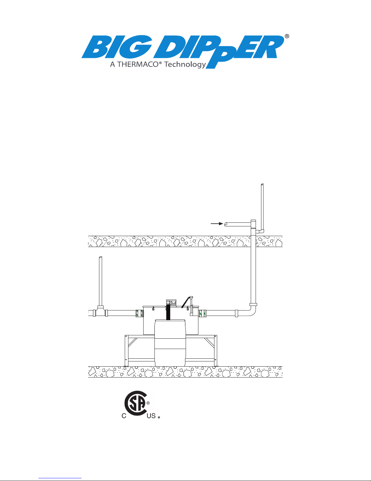
A Big Dipper W-750-AST in a
Basement Location
Kitchen Drainage Piping
©2015 Thermaco, Inc. All rights reserved • Patented/Patents Pending • Specications subject to change without notice
Thermaco, Inc. • 646 Greensboro St. • Asheboro, N. C. 27204-2548 • Phone (336) 629-4651 MNL-AST40000 2
40000 Series
Table of Contents
Table of Contents
AST System Overview 3
AST System Maintenance 4
AST Digital Control Operation 5
AST Function Operation 7
AST System Troubleshooting 8
How To Reverse AST System Operation 9
Plumbing Installation 10
Electrical Installation 13
AST System Wiring Diagram 14
AST Component Identication 16
AST Replacement Parts 18
Limited Warranty 19

©2015 Thermaco, Inc. All rights reserved • Patented/Patents Pending • Specications subject to change without notice
Thermaco, Inc. • 646 Greensboro St. • Asheboro, N. C. 27204-2548 • Phone (336) 629-4651 MNL-AST40000 3
40000 Series
The Thermaco, Inc. Big Dipper®Automatic Grease and Oils
Removal System removes free-oating grease & oils from kitchen
drain water ows. As most food service facility managers already
know, grease buildup within a building’s plumbing drainage system
is a major cause of problems due to drain line blockages. These
problems jeopardize normal operations as well as create health
and safety hazards within the facility itself.
The proper installation of a Big Dipper System can reduce or elimi-
nate grease problems. Use of the Big Dipper assures minimization and/or elimination of costly
sewer surcharges and nes through efcient separation and removal of free-oating grease & oils.
In addition, the Big Dipper also helps reduce or eliminate pumping and disposal costs associated
with conventional grease traps or interceptors. The recovered grease & oils are substantially
water-free and are suitable for recycling by local rendering and/or biodiesel companies.
The Big Dipper system is an automatic, self-cleaning device. As greasy kitchen efuent drains
from kitchen xtures, the unit traps the grease & oils. These separate from the efuent and rise
to the surface of the separator tank. The unit automatically skims the trapped grease & oils and
transfers the grease & oils to a collection container. A digital timer controls the self cleaning op-
eration, activating the skimming wheel at a user-set time. Only the “cleaned” water exits the unit
and ows into the facility drain lines.
Incidental food solids less than 1” (25 mm) in diameter (W-250-AST) and 1.5” (38 mm) in diam-
eter (W-750-AST & W-1250-AST) are separated and ushed out of the system automatically by
the Automatic Solids Transfer component. These incidental solids are typical of those that are
rinsed off of plates before going to a dishwasher. The Eductor Pump of the AST is not designed
to handle non-food products such as plastic, rubber or metal items.
The Big Dipper system’s compact footprint allows installation directly at the source, where grease
problems originate. The system design also allows easy maintenance and operation requiring
only a minimal amount of daily and weekly maintenance to maintain peak operating performance.
The Big Dipper system design allows for maximum installation exibility. Reversing the system
operation is as simple as rotating the cover assembly of the unit.
Grease interceptors, grease traps, automatic recovery units, grease removal devices and other
similar plumbing devices receiving kitchen ows from sinks, oor drains, woks and other food
bearing sources may generate odors. There are many factors inuencing odor evolution and dis-
semination. These include room ventilation, kitchen menu, ambient temperatures, ware washing
practices, grease/oil input, daily input uid volume, sanitizers, installation plumbing design and
product maintenance/upkeep. Odors are usually prevented by good area ventilation, frequent
uid inputs, good product maintenance practices and proper product installation. Additional steps,
including aeration, chlorination, improved area ventilation and additional maintenance control,
may be needed at some sites.
Big Dipper®Automatic Solids Transfer
(AST) System Overview
PROPERLY
DISPOSE OF
CONTENTS
DAILY
©2015 Thermaco, Inc. All rights reserved • Patented/Patents Pending • Specications subject to change without notice
Thermaco, Inc. • 646 Greensboro St. • Asheboro, N. C. 27204-2548 • Phone (336) 629-4651 MNL-AST40000 4
40000 Series
Big Dipper®Automatic Solids Transfer
(AST) System Maintenance
*CAUTION! DISCONNECT POWER TO UNIT BEFORE CLEANING
to prevent damage to the unit and personal injury
*NOTE: Before energizing unit after cleaning, ll tank with water
to protect wipers and heater from damage
Big Dipper®Automatic Solids Transfer (AST) System Maintenance
Daily Maintenance:
(A) Empty the clear plastic grease/oils collection container (located beside the unit) prior to its
becoming full once each day. The Big Dipper recovers grease and oil virtually water-free so that
they can be recycled. The collector container should be washed periodically so as to maintain
the easy viewing translucent characteristic of the collector.
Weekly Maintenance:
(A) Check the collection trough and the wiper blades for any solids build-up. Wipe off any accu-
mulated deposits and assure the wiper blades are clipped in place properly.
(B) Press the Jog Switch button (on the side of the center module) momentarily to ensure that
the motor and skimming wheel are still operating correctly.
(C) Remove & spray down the strainer assembly to remove any accumulated solids. Be sure to
spray down both the inside and outside surfaces of the strainer assembly.
(D) Check the thickness of the grease layer at the top of the unit. If there is more than a 1/2” (12
mm) thick layer of grease after the skimming cycle, this indicates a need to increase the skim-
ming time. Increase the digital control settings accordingly until a clean unit appearance is obtained
after the automatic skimming cycle. A simple guide is to change to the next higher setting (Light [I] to
Moderate [II] or Moderate [II] to Heavy [III]) and run for a period of time until enough grease is being
skimmed from the tank.
Quarterly Maintenance:
(A) The internal strainer assembly in the unit is designed to remove incidental solids from the
wastewater. Over a period of time, sediment consisting of very ne particles may begin to ac-
cumulate on the bottom of the unit. If this build-up is allowed to continue, it may eventually block
the outlet bafe. To prevent this from occurring, remove the lid and stir the bottom of the unit with
a long handled spatula while water is owing to ush out the sediment. Occasionally drain and
clean the unit thoroughly. Properly used, a wet vac may be appropriate for this purpose.
©2015 Thermaco, Inc. All rights reserved • Patented/Patents Pending • Specications subject to change without notice
Thermaco, Inc. • 646 Greensboro St. • Asheboro, N. C. 27204-2548 • Phone (336) 629-4651 MNL-AST40000 5
40000 Series
VOICE 336-629-4651 FAX 336-626-5739
PO BOX 2548, ASHEBORO, NC 27203
646 GREENSBORO STREET
DESTROY THIS DRAWING, IT IS THE SOLE PROPERTY OF THERMACO, INC. AND MUST BE RETURNED UPON REQUEST.
OF THIS DRAWING DOES CONSTITUTE AN IMPLIED AGREEMENT BETWEEN THERMACO, INC. AND THE HOLDER OF THIS DRAWING. DO NOT
WRITTEN CONSENT FROM THERMACO, INC. POSSESSION OF THIS DRAWING DOES NOT CONSTITUTE THE RIGHT TO MANUFACTURE. POSSESSION
THIS DRAWING CONTAINS PROPRIETARY AND PATENTED MATERIAL. THIS DRAWING MAY NOT BE REPRODUCED IN WHOLE OR IN PART WITHOUT
.XXX +/- 0.015
.XX +/- 0.03
Decimals
+/-1°
Angular
Tolerances
Dimensions are in inches
Unless otherwise specified
MATERIAL (UNLESS NOTED)
FINISH (UNLESS NOTED) PART NO.
CHECKED
ENGINEERING
DRAWN DATE
A
THIRD ANGLE PROJECTION
RELEASE DATE
REVISIONS
ZONE REV DESCRIPTION DATE APPROVED
SCALE SHEET OF
SIZE REV. NO. DWG NO.
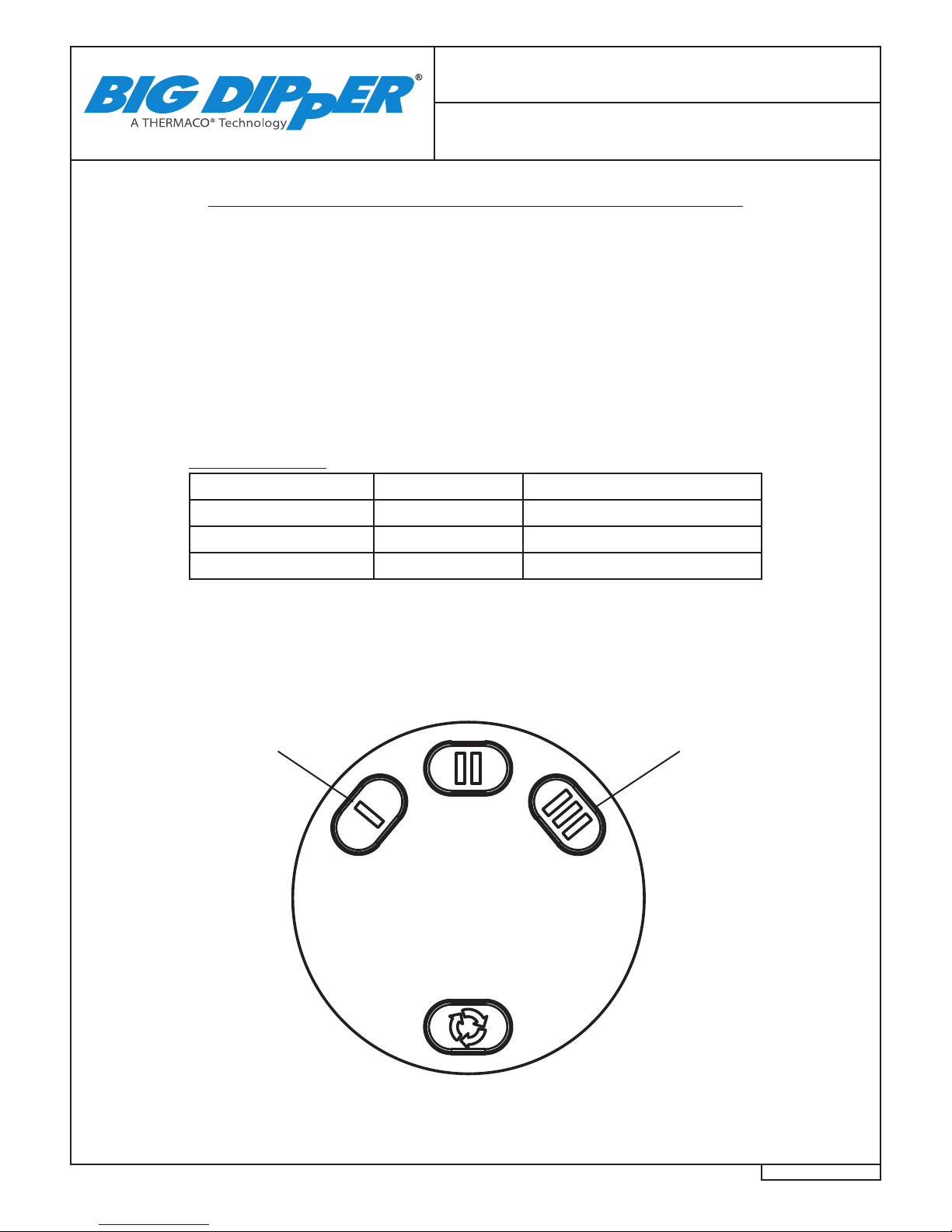
Digital Control Operation (Default Modes)
Big Dipper®AST System
Digital Control Operation
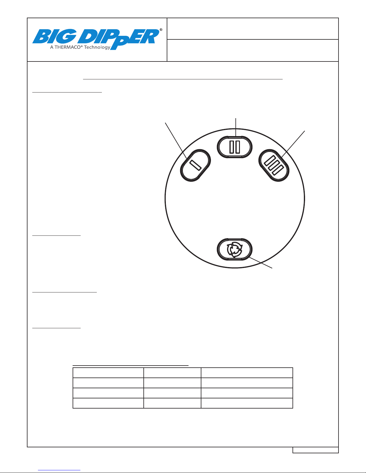
Timed Skimming Default
Through the “User Interface” three
levels of skimming may be selected in
the “default” mode. By selecting one of
the skimming buttons – I, II, or III - the
skimming cycle (see table below) is
activated. The LED associated with
the selected button is illuminated
continuously as an indicator of the
selected skim cycle and as a “power
on” indicator. If the skimming level is
changed during an active skimming
cycle, the next active skim cycle will be
at the new setting (The LED associated
with the newly selected level will change
immediately). If the skimming cycle
is changed between active skimming
cycles the next skim cycle will be at the
new level.
Motor Exercising
For all default mode skimming levels, the
motor will be energized for 30 seconds
every 9.5 hours. Only the motor will be
energized (no heater operation) at these
exercising times.
Heavy Setting:
Recommended for
Heavy Grease Output
(Steakhouses, Buffets,
Heavy Grease
producing sites***)
Start Button: Press
to begin a cycle early
or to test operation..
Light Setting:
Recommended for
Light Grease Output
(Small Cafes, Coffee/
Ice Cream shops***)
Moderate Setting:
Recommended for
Moderate Grease Output
(Quick and Full-Service
restaurants***)
Start Button Operation
Any time the start button is depressed the “time between skims” the digital control goes to its maximum time and
operation begins for the selected skim level. After this skimming cycle the normal time delay to the next skim cycle
is used (skim cycle resets when the start button is depressed).
Heater Operation
The heater operates under Thermistor control any time the skimmer motor is energized and anytime the liquid
temperature drops to 40º F to prevent liquid from freezing. Contact Thermaco for programming alternative heater
settings.
Default Modes - Normal Operation*
Button Selected Skim Time Delay Between Skims**
Light (I) 15 Minutes 76 Hours
Moderate (II) 30 Minutes 19 Hours
Heavy (III) 60 Minutes 19 Hours
* For Extreme Conditions see next page.
** Delay between Skims is the time from the start of the 1st skim to the start of the next skim.
*** Only examples, actual mode needed will vary depending upon menu, warewashing procedures, etc.
©2015 Thermaco, Inc. All rights reserved • Patented/Patents Pending • Specications subject to change without notice
Thermaco, Inc. • 646 Greensboro St. • Asheboro, N. C. 27204-2548 • Phone (336) 629-4651 MNL-AST40000 6
40000 Series
Digital Control Operation (Extreme Modes)
Big Dipper®AST System
Digital Control Operation
Extreme Operation
For Food Service Operations which produce more grease and need additional run-time, the 40000 Series Big Dipper
provides additional modes for extreme operation. In order to access these modes:
1. Remove power from CLA by unplugging unit or lifting it to disengage the safety switch (found on
underside of the back of assembly).
2. Reapply power while holding down the Heavy Mode (III) Button.
3. The button (III) will blink temporarily, indicating which operation level has been selected.
4. Select desired mode at skim times/frequencies listed below.
Extreme Modes
Button Selected Skim Time Delay Between Skims*
Light (I) 90 Minutes 19 Hours
Moderate (II) 120 Minutes 19 Hours
Heavy (III) 120 Minutes 9.5 Hours
* Delay between Skims is the time from the start of the 1st skim to the start of the next skim.
To return to Default Modes, follow the instructions above, but press the Light Mode (I) Button instead of the Heavy
Mode (III) Button. The Light Mode (I) Button will temporarily blink to indicate this operational level has been
selected.
VOICE 336-629-4651 FAX 336-626-5739
PO BOX 2548, ASHEBORO, NC 27203
646 GREENSBORO STREET
DESTROY THIS DRAWING, IT IS THE SOLE PROPERTY OF THERMACO, INC. AND MUST BE RETURNED UPON REQUEST.
OF THIS DRAWING DOES CONSTITUTE AN IMPLIED AGREEMENT BETWEEN THERMACO, INC. AND THE HOLDER OF THIS DRAWING. DO NOT
WRITTEN CONSENT FROM THERMACO, INC. POSSESSION OF THIS DRAWING DOES NOT CONSTITUTE THE RIGHT TO MANUFACTURE. POSSESSION
THIS DRAWING CONTAINS PROPRIETARY AND PATENTED MATERIAL. THIS DRAWING MAY NOT BE REPRODUCED IN WHOLE OR IN PART WITHOUT
.XXX +/- 0.015
.XX +/- 0.03
Decimals
+/-1°
Angular
Tolerances
Dimensions are in inches
Unless otherwise specified
MATERIAL (UNLESS NOTED)
FINISH (UNLESS NOTED) PART NO.
CHECKED
ENGINEERING
DRAWN DATE
A
THIRD ANGLE PROJECTION
RELEASE DATE
REVISIONS
ZONE REV DESCRIPTION DATE APPROVED
SCALE SHEET OF
SIZE REV. NO. DWG NO.
Hold down Heavy
Mode (III) Button
when connecting
power to unit to
switch to extreme
modes.
Hold down Light
Mode (I) Button
when connecting
power to unit to
switch back to
default modes.

©2015 Thermaco, Inc. All rights reserved • Patented/Patents Pending • Specications subject to change without notice
Thermaco, Inc. • 646 Greensboro St. • Asheboro, N. C. 27204-2548 • Phone (336) 629-4651 MNL-AST40000 7
40000 Series
Automatic Solids Transfer (AST) Function Operation
Big Dipper®AST
Function Operation
The Automatic Solids Transfer feature in Big Dipper AST models function to ush solids of a certain size out of the
unit and into the sewer collection system where it can be dealt with properly, while not interfering with the regular
separation and isolation of free oating fats, oils, and grease. Each AST Unit comes with a Solids Strainer Assembly,
which separates out solids, and a Eductor Pump which periodically ushes the contents of the strainer.
W-250-AST
The Strainer Basket Assembly separates incidental solids less than 1” (25mm) in diameter, allowing larger solids
to settle in the Strainer Basket Assembly and grease efuent to ow into the main tank. Every 24 hours (beginning
with initial power application), the eductor pump runs for 10 seconds, ushing the incidental solids from the system.
The AST Function’s operating frequency is reset by pressing the start button.
W-750-AST and W-1250-AST
The Strainer Basket Assembly separates incidental solids less than 1.5” (38mm) in diameter, allowing larger solids
to settle in the Strainer Basket Assembly and grease efuent to ow into the main tank. Every 2 hours (beginning
with initial power application), the eductor pump runs for 15 seconds, ushing the incidental solids from the system.
The AST Function’s operating frequency is reset by pressing the start button.
Clean Water Flow
Through Outlet Bafe
Solids Evacuated to
Outlet Flow
Solids Trapped in
Solids Chamber
Efuent Flow
Inlet
Greasy Efuent
Rises Through
Chamber
Heating
Element
Skimming Wheel
Assembly
Digital
Control
Grease Skimmed off
Top and Emptied Through
Grease Outlet Clean Water Flow
from Outlet

©2015 Thermaco, Inc. All rights reserved • Patented/Patents Pending • Specications subject to change without notice
Thermaco, Inc. • 646 Greensboro St. • Asheboro, N. C. 27204-2548 • Phone (336) 629-4651 MNL-AST40000 8
40000 Series
Big Dipper®AST System
Troubleshooting
Big Dipper unit overows
(1) Check to see that the outlet pipe is not reduced to a
smaller size, the outlet piping is vented, has as few 90
degree outlet turns as possible, and that no “P” trap is
installed on the outlet. Re-plumb the piping, if neces-
sary. Check outlet piping for clogs. Have a plumber
clean the line, if necessary.
(2) Make sure that the solids collection chamber is free
of excessive debris. To check Eductor Pump operation,
unplug the unit for 10 seconds, then re-renergize. The
Eductor Pump should automatically activate.
(3) Check the bottom of the grease chamber for exces-
sive solids and silt buildup which may be blocking the
outlet bafe. Disconnect the power and use a long
handled spatula or similar instrument to stir the bottom
while water ows through the unit. If necessary, drain
and clean the sediment from the unit. To prevent recur-
rence, schedule this cleaning to be done on a regular
basis (properly used, a wet vac may be appropriate for
cleaning sediment from the bottom of the unit).
(4) Make sure the ow rate to the unit does not exceed
the maximum ow rate, which is shown on the nameplate.
If necessary, have a plumber install an approved ow
control to restrict the inlet ow to the specied level or
install a properly sized Big Dipper for the application.
Excessive water observed in the grease collection
container
(1) Check Digital Control for excessive “on” time. Unit
will pick up incidental water after all grease is removed.
If necessary, reduce the digital control setting (i.e.
Moderate [II] to Light [I]) until no water is observed in
the grease collection container.
(2) Make sure that the water ow to the unit does not
exceed the rated ow and there are no drain line clogs
downstream from the unit.
No grease is collected in the container
(1) Check to be sure the power is on and the correct
setting is chosen. One of the setting buttons should be
illuminated. If none of the setting buttons are illuminated,
the unit is not powered.
(2) Lift the sump cover and clean away any buildup
that may be present on the wiper blades or collection
trough. Make sure the wiper blade(s) are properly in
place on the skimmer wheels. Replace wiper blades
when worn or warped.
(3) Press the Start Button on the bottom of the user inter-
face to ensure that the skimming wheel turns.
CAUTION: Keep your hands away from moving parts
to avoid possible injury. If the skimmer motor does not
come on, the motor assembly may need to be replaced.
(4) Check for congealed grease in the unit. If the Big
Dipper’s heating element is not warming the unit, the
heating element may need to be replaced.
(5) Some sites do not generate enough grease to be
captured by the skimming process. Set Control for
minimum operation - Setting [I] for Light Skimming
Operation.
Objectionable odor
(1) Make sure grease/oil is being skimmed properly
from the unit.
(2) Check Digital Control for excessive “on” time. Unit
will pick up incidental water after all grease is removed.
If necessary, reduce the digital control setting (i.e.
Moderate [II] to Light [I]) until no water is observed in
the grease collection container.
(3) If excessive sediment has collected on the bottom
of the unit, clean the unit as described in item 3 in “Big
Dipper unit overows.”
(4) Clean the solids strainer assembly and grease col-
lection container more frequently.
(5) Grease interceptors, grease traps, automatic re-
covery units, grease removal devices and other similar
plumbing devices receiving kitchen ows from sinks,
oor drains, woks and other food bearing sources may
generate odors. There are many factors inuencing
odor evolution and dissemination. These include room
ventilation, kitchen menu, ambient temperatures, ware
washing practices, grease/oil input, daily input uid vol-
ume, sanitizers, installation plumbing design and product
maintenance/upkeep. Odors are usually prevented by
good area ventilation, frequent uid inputs, good product
maintenance practices and proper product installa-
tion. Additional steps, including aeration, chlorination,
improved area ventilation and additional maintenance
control, may be needed at some sites.
©2015 Thermaco, Inc. All rights reserved • Patented/Patents Pending • Specications subject to change without notice
Thermaco, Inc. • 646 Greensboro St. • Asheboro, N. C. 27204-2548 • Phone (336) 629-4651 MNL-AST40000 9
40000 Series
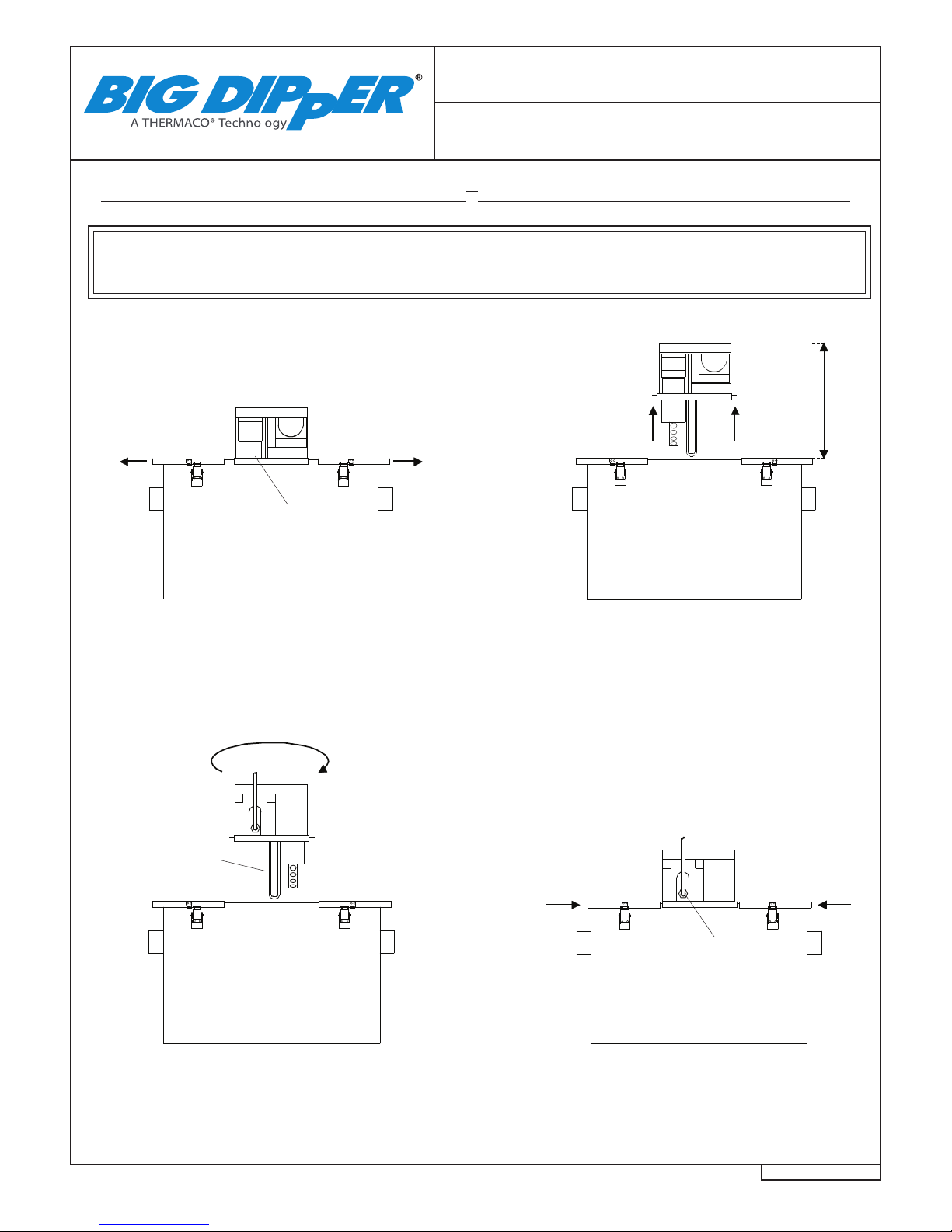
How To Reverse Big Dipper®
AST System Operation
1) Unlatch the Unit lid. Pull the
side wings outward.
2) Lift the center module up off of
the unit, ensuring clearance for the
heater.
3) Rotate the center module
180º.
4) Lower the center module back
down on top of the unit. Move the
two side wings back into place
& fasten all latches.
1) 2)
4)3)
Grease
Outlet
Heater
Power
Cord
How To Reverse Big Dipper®AST System Unit Operation
Clearance Required
To Remove Lid
*ALWAYS UNPLUG UNIT BEFORE REMOVING LID
*SYSTEM WILL NOT OPERATE UNLESS CENTER MODULE IS IN PLACE
14.000”
*Note:
W-250-AST & W-750-AST have one (1) module.
W-1250-AST has two (2) modules.
©2015 Thermaco, Inc. All rights reserved • Patented/Patents Pending • Specications subject to change without notice
Thermaco, Inc. • 646 Greensboro St. • Asheboro, N. C. 27204-2548 • Phone (336) 629-4651 MNL-AST40000 10
40000 Series
Big Dipper®AST System
Plumbing Installation
Locating the Unit
To minimize grease build-up in piping, a Big Dip-
per system should be located as close as possible
to the xture it is serving. The system should be
visible and easily accessible for maintenance and
inspection. The unit must be in a level position.
Be sure to check the Specication Sheet for
your model for the exact clearances needed for
installation. If the system is located directly on the
oor, the bottom should be sealed to the oor with
an approved silicone type sealant. Make sure the
height above the strainer access cover is enough
to remove the strainer basket assembly.
Eductor Pump
The facility must provide a minimum 50 PSI (3.45
Bar) water supply to the Eductor pump on the AST
system. Thermaco, Inc. provides a Female Connec-
tor (0.5”/12 mm with W-250-AST and 0.75”/19mm
with W-750/1250-AST) to connect to this water
supply. The eductor pump on the W-250-AST is
designed to handle incidental food solids of less than
1” (25 mm) in diameter. The eductor pump on the
W-750-AST & W-1250-AST is designed to handle
incidental food solids of less than 1.5” (38 mm) in
diameter. Non-food products including plastic and
metal parts cannot be removed by the Eductor.
The W-250-AST requires at least 5 GPM (0.32
l/s) ow for proper operation. The W-750-AST
& W-1250-AST require at least a 12 GPM (0.75
l/s) ow for proper operation. The Eductor pump
includes a water hammer arrestor.
Inlet/Outlet Piping
The inlet and outlet piping connections require exible
sleeve pipe couplings. Keep outlet piping as straight
as possible. Use only “sweep” connections. Do not
reduce the pipe sizing on the outlet piping. Do not
install “P” trap on outlet connection of system. (Note:
The system already has a internal gas trap)
Flow Controls
Big Dipper systems are equipped with an internal
ow control located inside the inlet end of the system.
Verify its location and placement prior to connecting
the inlet piping.
Fill Unit With Water Before Applying Power
Big Dipper systems, equipped with an electric
heating element, MUST be lled with water before
energizing the power to the system. Failure to do
so may damage the electric heating element. These
elements will NOT be replaced under Thermaco’s
Warranty.
Venting the Outlet
An outlet vent or approved vacuum breaker of at least
1/2 the diameter of the system’s outlet connection
must be present as close as possible to the Big Dipper
outlet to prevent possible siphonage problems. Failure
to provide a vent for the system voids Thermaco’s
Warranty for the system.
For High Head Height Applications Over Six (6)
Feet (1.95 m)
Big Dipper systems are equipped with an internal
ow regulator located inside the inlet end of the
system. Verify its location and placement prior to
connecting the inlet piping. If your code requires
a vertical type ow regulator, an approved control
with a ow rating matching the system’s ow rate
should be used. Note: When a Big Dipper is servic-
ing multiple xtures, some codes require separate
ow controls for each xture. See following page
for suggested high head height ow regulation
installation.
Do Not Use With Food Grinders, Potato Peelers
or Waste Disposal Units
If the system is connected to a Waste Disposal Unit,
Garbage Grinder or Potato Peeler, Thermaco’s War-
ranty will be void.
Note: Drawing for reference only.
Equipment must be installed in
compliance with all applicable laws,
regulations and codes, including
plumbing codes. Installation should
be performed by a qualied plumber.
Big Dipper®AST System Plumbing Installation
©2015 Thermaco, Inc. All rights reserved • Patented/Patents Pending • Specications subject to change without notice
Thermaco, Inc. • 646 Greensboro St. • Asheboro, N. C. 27204-2548 • Phone (336) 629-4651 MNL-AST40000 11
40000 Series
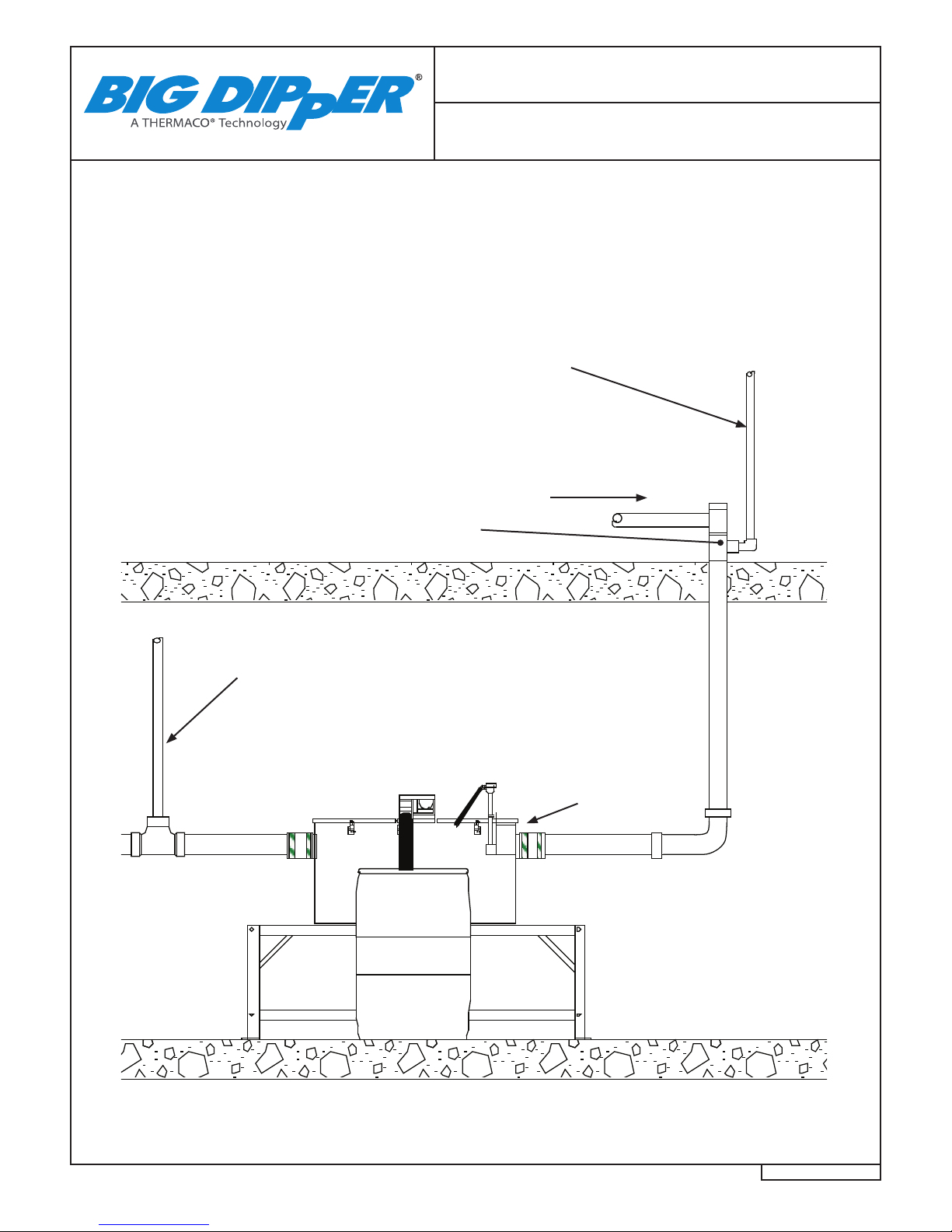
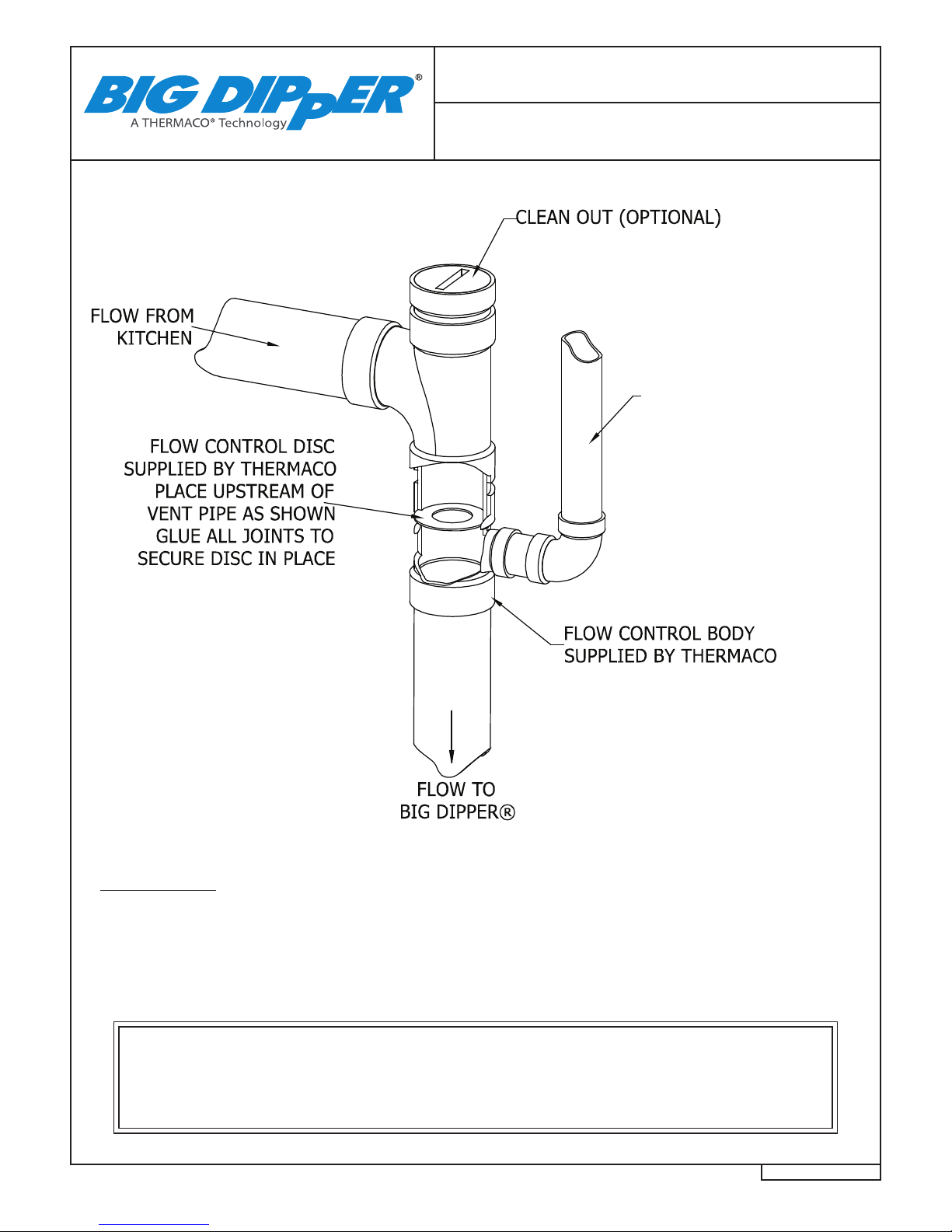
NOTE: Drawing for reference only. Equipment must be installed in compliance with all applicable laws, regu-
lations and codes, including plumbing codes. Installation should be performed by a qualied plumber.
Big Dipper®AST System
Plumbing Installation
Drainage Piping
from Kitchen
VFCA-25 Vented Flow Control for W-250-AST
VFCA-75 Vented Flow Control for W-750-AST
VFCA-125 Vented Flow Control for W-1250-AST
Outlet Vent
(Note: Vent may be facility vent connection or
code-approved air admittance valve)
* Installation in high head height
locations requires removal of the
Internal Flow Control (small rub-
ber cap under no-hub coupling
over the Inlet).
Sometimes space restrictions require the installation of Big Dipper units in basement locations where signicant
head pressure becomes a factor. The Big Dipper® VFCA Vented Flow Control module provides an option for use
with installations where a signicant amount of head pressure is present (greater than 6 ft./1.95 m) or where ap-
plicable regulations require vented ow controls. A Vented Flow Control helps reduce problems associated with
high head pressure and helps slow the drainwater ow down. The VFCA kit contains an appropriate tting and
ow control orice.
Flow Control Vent/Air Intake
(Note: Flow Control Vent may be connected to
atmosphere vent, facility vent, or code-approved
air admittance valve. To be installed above sink
ood rim.)
©2015 Thermaco, Inc. All rights reserved • Patented/Patents Pending • Specications subject to change without notice
Thermaco, Inc. • 646 Greensboro St. • Asheboro, N. C. 27204-2548 • Phone (336) 629-4651 MNL-AST40000 12
40000 Series
FLOW CONTROL VENT
MAY BE CONNECTED TO
ATMOSPHERE VENT,
FACILITY VENT, OR
CODE-APPROVED AIR
ADMITTANCE VALVE.*
TO BE INSTALLED
ABOVE SINK FLOOD
RIM.
*Air Admittance Valves are not
permitted in some locations. Check
local plumbing code to determine
if they are permitted by state or
local plumbing code.
VFCA Vented Flow Control
Installation Instructions
IMPORTANT!
The ow control should be installed after the last xture as close as possible to the
under side of the lowest xture. If the ow control is installed more than 2 feet
below the lowest xture consult the manufacturer for a more restrictive disc.
Remove the rubber ow control from the Big Dipper system.
Note: This equipment must be installed to comply with all
applicable national, state, and local plumbing codes for your area.
Installation should only be performed by a qualied plumber.
©2015 Thermaco, Inc. All rights reserved • Patented/Patents Pending • Specications subject to change without notice
Thermaco, Inc. • 646 Greensboro St. • Asheboro, N. C. 27204-2548 • Phone (336) 629-4651 MNL-AST40000 13
40000 Series
PROPERLY
DISPOSE OF
CONTENTS
DAILY
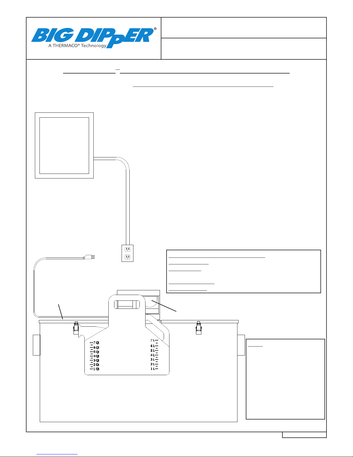
Big Dipper®AST System
Electrical Installation
Big Dipper®AST System Electrical Installation
Electrical Panel
(NOT SUPPLIED)
Duplex Outlet
(NOT SUPPLIED)
Big Dipper Automatic Solids Transfer (AST) Models
The Big Dipper W-250-AST & W-750-AST models are equipped with one (1)
Push Button Digital Time Controller while the W-1250-AST model is equipped
with two (2) Push Button Digital Time Controllers. The push button control
is located under the hinged lid of the motor enclosure on top of the lid of Big
Dipper (See Digital Timer Operation Instructions). The Big Dipper should
only be plugged into a properly grounded 3-prong 120 VAC or 230 VAC
outlet. If possible, the power supply outlet for the Big Dipper should be
connected to an electrical circuit controlled by a ground fault circuit breaker.
One of the setting buttons should be illuminated to show the unit is pow-
ered. If none of the setting buttons are illuminated, the unit is not powered.
This Big Dipper unit is shipped from the Factory wired for Simultaneous
Operation. This means the Heater and Motor operate at the same time
under digital control. Continuous Heater Operation is where the Heater is
active at all times. To switch to alternative heating programming, please
contact a Thermaco representative for furher instructions.
Note: The Big Dipper unit will not operate when the lid is removed.
Digital Control
(Under Hinged Lid)
Electrical Junction
Box (Hidden)
*W-1250-AST Only
Note:
Digital Control Supplied with
system.
Drawing for reference only.
Equipment must be installed
in compliance with all appli-
cable laws, regulations and
codes, including electrical
codes. Installation should
be performed by a qualied
electrician.
115VAC Circuit,
From Ground Fault
Circuit Breaker
(NOT SUPPLIED)
*For 230 VAC Units use
230 VAC Circuit
Big Dipper Electrical Requirements
W-250/750-AST: 4.6 Amps @ 115VAC 50/60Hz (535 Watts)
W-1250-AST: 9.1 Amps @ 115VAC 50/60Hz (1055 Watts)
*For 230 VAC Units:
W-250/750-AST-E: 2.3 Amps @ 230VAC 50/60Hz (535 Watts)
W-1250-AST-E: 4.6 Amps @ 230 VAC 50/60Hz (1055 Watts)

©2015 Thermaco, Inc. All rights reserved • Patented/Patents Pending • Specications subject to change without notice
Thermaco, Inc. • 646 Greensboro St. • Asheboro, N. C. 27204-2548 • Phone (336) 629-4651 MNL-AST40000 14
40000 Series
Big Dipper®AST System
Wiring Diagram
NOTE:
220-240V Units (International Units) have the
following wire color changes:
On the POWER SUPPLY CORD:
The Black Wire becomes Brown
The White Wire becomes Blue
The Green Wire becomes Yellow/Green
Wiring Diagram For Big Dipper Models:
W-250-AST and W-750-AST
1
1
2
2
3
3
4
4
A A
B B
MATERIAL (UNLESS NOTED)
FINISH (UNLESS NOTED)
646 GREENSBORO STREET
PO BOX 2548, ASHEBORO, NC 27203
VOICE 336-629-4651 FAX 336-626-5739 Decimals
.XX +/- .03
.XXX +/- .015
Unless otherwise specified
Dimensions are in inches
Tolerances
Angular
+/- 1°
CHECKED SIZE REV. NO. DWG NO.
PART NO.
SCALE RELEASE DATE SHEET OF
ENGINEERING
DRAWN DATE
THIRD ANGLE PROJECTION
B
1
2
3
BLACK
INTERLOCK
SWITCH
MOTOR
GREEN (GREEN/YELLOW)
GREEN
HEATER
GROUND WIRE ATTACHED
TO HEATER
THERMISTOR
BLACK (BROWN)
N
115
230
POWER SUPPLY CORD
RING TERMINALS TO GROUND STUD
ON MOTOR MOUNT BRACKET
WHITE (BLUE)
115 V INPUT TERMINAL
230V INPUT TERMINAL
WIRING DIAGRAM PUSH BUTTON
CONTROLLED BIG DIPPER
W SERIES S/N 30000 AND ABOVE
0WD-IS-PBC
03/17/09 1 1
NTS
B. KYLES 03/17/09
REVISION HISTORY
ZONE REV DESCRIPTION DATE APPROVED
BLACK
USER INTERFACE
MAIN BOARD
RIBBON CABLE

©2015 Thermaco, Inc. All rights reserved • Patented/Patents Pending • Specications subject to change without notice
Thermaco, Inc. • 646 Greensboro St. • Asheboro, N. C. 27204-2548 • Phone (336) 629-4651 MNL-AST40000 15
40000 Series
Big Dipper®AST System
Wiring Diagram
NOTE:
220-240V Units (International Units) have the
following wire color changes:
On the POWER SUPPLY CORD:
The Black Wire becomes Brown
The White Wire becomes Blue
The Green Wire becomes Yellow/Green
Wiring Diagrams for Big Dipper Model: W-1250-AST
1
1
2
2
3
3
4
4
A A
B B
MATERIAL (UNLESS NOTED)
FINISH (UNLESS NOTED)
646 GREENSBORO STREET
PO BOX 2548, ASHEBORO, NC 27203
VOICE 336-629-4651 FAX 336-626-5739 Decimals
.XX +/- .03
.XXX +/- .015
Unless otherwise specified
Dimensions are in inches
Tolerances
Angular
+/- 1°
CHECKED SIZE REV. NO. DWG NO.
PART NO.
SCALE RELEASE DATE SHEET OF
ENGINEERING
DRAWN DATE
THIRD ANGLE PROJECTION
B
1
2
3
BLACK
INTERLOCK
SWITCH
MOTOR
GREEN (GREEN/YELLOW)
GREEN
HEATER
GROUND WIRE ATTACHED
TO HEATER
THERMISTOR
BLACK (BROWN)
N
115
230
POWER SUPPLY CORD
RING TERMINALS TO GROUND STUD
ON MOTOR MOUNT BRACKET
WHITE (BLUE)
115 V INPUT TERMINAL
230V INPUT TERMINAL
WIRING DIAGRAM PUSH BUTTON
CONTROLLED BIG DIPPER
W SERIES S/N 30000 AND ABOVE
0WD-IS-PBC
03/17/09 1 1
NTS
B. KYLES 03/17/09
REVISION HISTORY
ZONE REV DESCRIPTION DATE APPROVED
BLACK
USER INTERFACE
MAIN BOARD
RIBBON CABLE
Center Module #1: AST Control
1
1
2
2
3
3
4
4
A A
B B
MATERIAL (UNLESS NOTED)
FINISH (UNLESS NOTED)
646 GREENSBORO STREET
PO BOX 2548, ASHEBORO, NC 27203
VOICE 336-629-4651 FAX 336-626-5739 Decimals
.XX +/- .03
.XXX +/- .015
Unless otherwise specified
Dimensions are in inches
Tolerances
Angular
+/- 1°
CHECKED SIZE REV. NO. DWG NO.
PART NO.
SCALE RELEASE DATE SHEET OF
ENGINEERING
DRAWN DATE
THIRD ANGLE PROJECTION
B
1
2
3
BLACK
INTERLOCK
SWITCH
MOTOR
GREEN (GREEN/YELLOW)
GREEN
HEATER
GROUND WIRE ATTACHED
TO HEATER
THERMISTOR
BLACK (BROWN)
N
115
230
POWER SUPPLY CORD
RING TERMINALS TO GROUND STUD
ON MOTOR MOUNT BRACKET
WHITE (BLUE)
115 V INPUT TERMINAL
230V INPUT TERMINAL
WIRING DIAGRAM PUSH BUTTON
CONTROLLED BIG DIPPER
W SERIES S/N 30000 AND ABOVE
0WD-IS-PBC
03/17/09 1 1
NTS
B. KYLES 03/17/09
REVISION HISTORY
ZONE REV DESCRIPTION DATE APPROVED
BLACK
USER INTERFACE
MAIN BOARD
RIBBON CABLE
Center Module #2: Normal Skimming Operation
©2015 Thermaco, Inc. All rights reserved • Patented/Patents Pending • Specications subject to change without notice
Thermaco, Inc. • 646 Greensboro St. • Asheboro, N. C. 27204-2548 • Phone (336) 629-4651 MNL-AST40000 16
40000 Series
1
1
2
2
3
3
4
4
A A
B B
C C
D D
THIS DRAWING CONTAINS PROPRIETARY AND PATENTED MATERIAL. THIS DRAWING MAY NOT BE REPRODUCED IN WHOLE OR PART WITHOUT
WRITTEN CONSENT FROM THERMACO, INC. POSSESSION OF THIS DRAWING DOES NOT CONSTITUTE THE RIGHT TO MANUFACTURE.
POSSESSION OF THIS DRAWING DOES CONSTITUTE AN IMPLIED NONDISCLOSURE AGREEMENT BETWEEN THERMACO, INC. AND THE HOLDER OF
THIS DRAWING. DO NOT DESTROY THIS DRAWING, IT IS THE SOLE PROPERTY OF THERMACO, INC. AND MUST BE RETURNED UPON REQUEST.
MATERIAL (UNLESS NOTED)
FINISH (UNLESS NOTED)
646 GREENSBORO STREET
PO BOX 2548, ASHEBORO, NC 27203
VOICE 336-629-4651 FAX 336-626-5739 Decimals
.XX +/- .03
.XXX +/- .015
Unless otherwise specified
Dimensions are in inches
Tolerances
Angular
+/- 1°
CHECKED SIZE REV. NO. DWG NO.
PART NO. C
SCALE RELEASE DATE SHEET OF
ENGINEERING
DRAWN DATE
THIRD AN GLE PRO JECTION
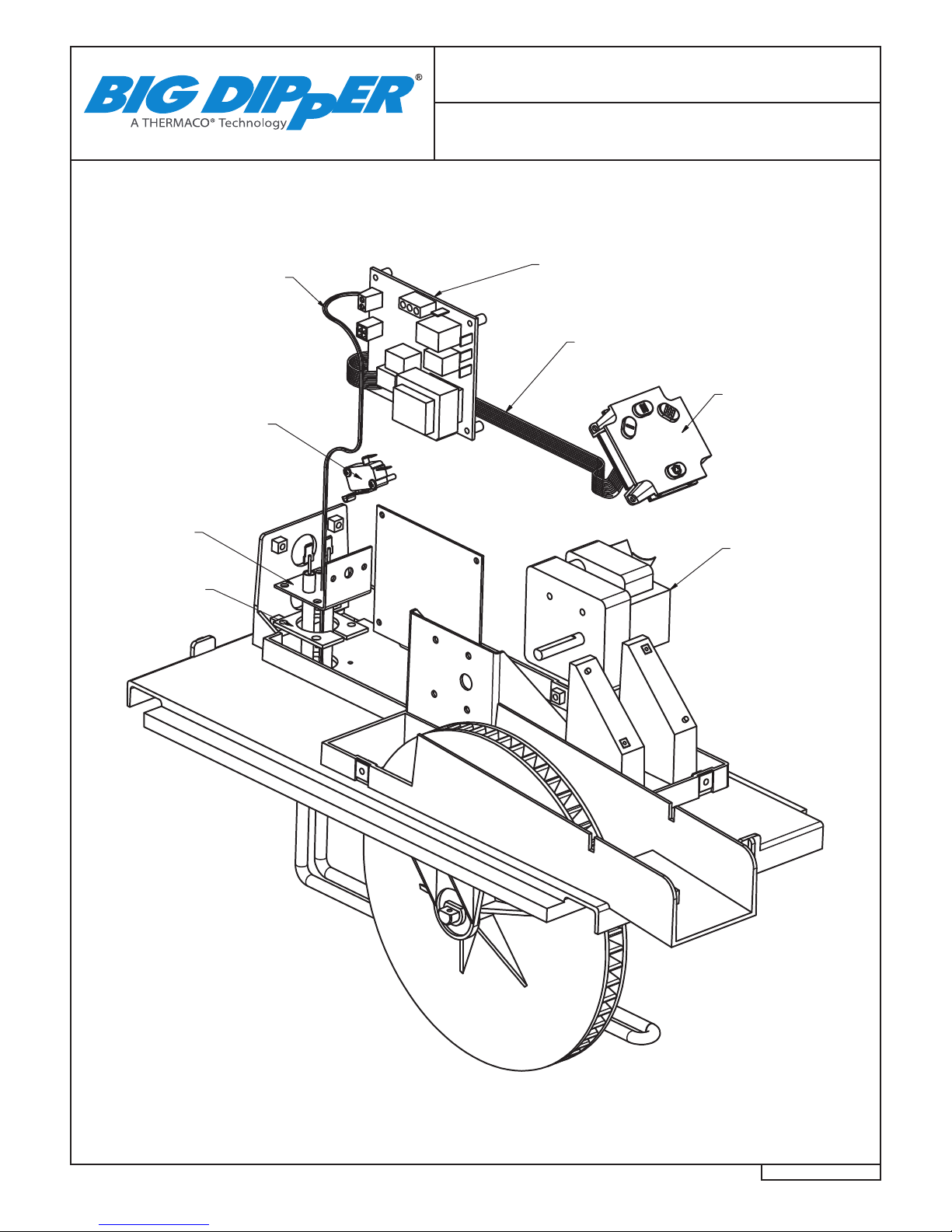
Motor
Part# M-58*
Safety Switch
Part# MSS-7
Heater
Part# H-8*
Heater Gasket
Part# HTG-300
Control Assembly
Part# PCBA-2
Consisting of
1- Printed Circuit Board
2- User Interface Assembly
3- Thermistor w/Wiring
4- Ribbon Cable w/Connectors
4-Ribbon Cable
(Part of PCBA-2)
2-User Interface
(Part of PCBA-2)
3-Thermistor
(Part of PCBA-2)
Big Dipper®AST System
Electrical Components
*Note:
W-750-AST system requires one (1)
W-1250-AST system requires two (2)
** 230 VAC Units use M-58-230
and H-8-230
©2015 Thermaco, Inc. All rights reserved • Patented/Patents Pending • Specications subject to change without notice
Thermaco, Inc. • 646 Greensboro St. • Asheboro, N. C. 27204-2548 • Phone (336) 629-4651 MNL-AST40000 17
40000 Series
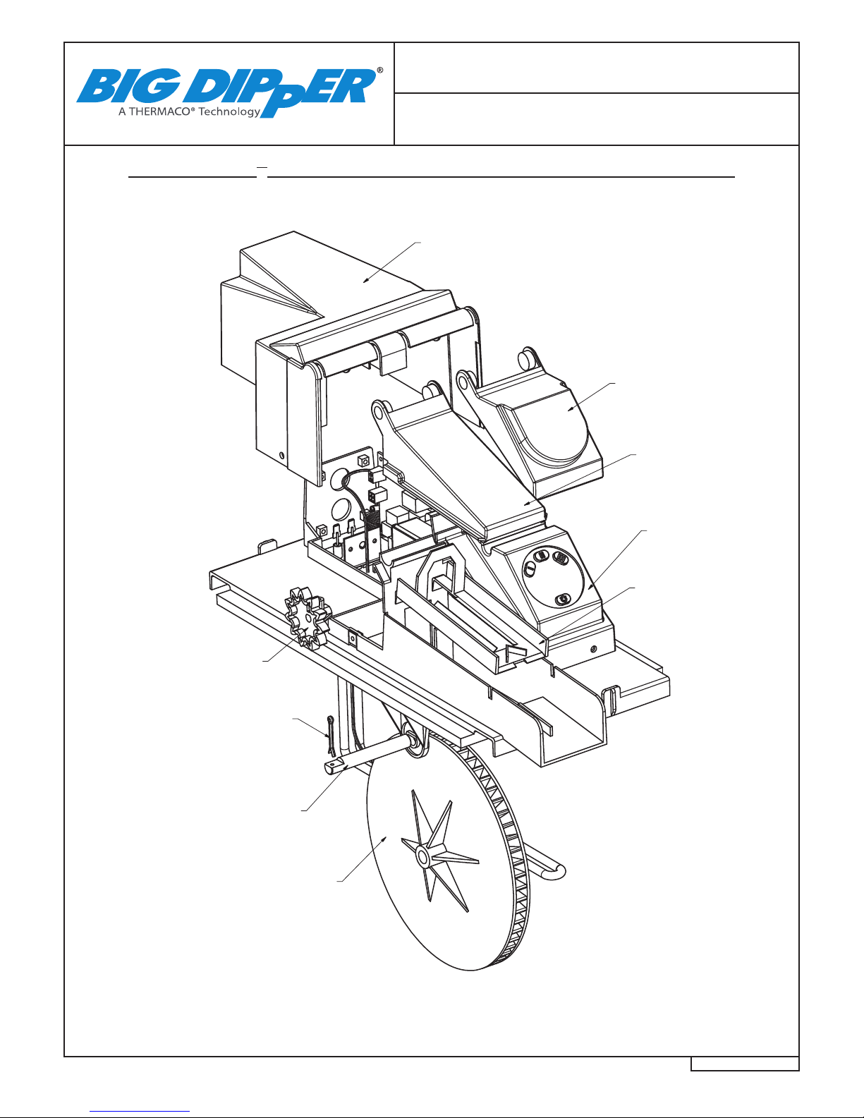
Big Dipper®AST System
Component Identication
Big Dipper® AST System Component Identication
1
1
2
2
3
3
4
4
A A
B B
C C
D D
THIS DRAWING CONTAINS PROPRIETARY AND PATENTED MATERIAL. THIS DRAWING MAY NOT BE REPRODUCED IN WHOLE OR PART WITHOUT
WRITTEN CONSENT FROM THERMACO, INC. POSSESSION OF THIS DRAWING DOES NOT CONSTITUTE THE RIGHT TO MANUFACTURE.
POSSESSION OF THIS DRAWING DOES CONSTITUTE AN IMPLIED NONDISCLOSURE AGREEMENT BETWEEN THERMACO, INC. AND THE HOLDER OF
THIS DRAWING. DO NOT DESTROY THIS DRAWING, IT IS THE SOLE PROPERTY OF THERMACO, INC. AND MUST BE RETURNED UPON REQUEST.
MATERIAL (UNLESS NOTED)
FINISH (UNLESS NOTED)
646 GREENSBORO STREET
PO BOX 2548, ASHEBORO, NC 27203
VOICE 336-629-4651 FAX 336-626-5739 Decimals
.XX +/- .03
.XXX +/- .015
Unless otherwise specified
Dimensions are in inches
Tolerances
Angular
+/- 1°
CHECKED SIZE REV. NO. DWG NO.
PART NO. C
SCALE RELEASE DATE SHEET OF
ENGINEERING
DRAWN DATE
THIRD ANG LE PROJEC TION
Front Electrical
Enclosure Digital
Part# FEEA-1
Wheel Wiper Assembly
Part# WWA-4
Control Cover
Part# MTC-1
Wheel Cover
Part# MSC-1
Rear Electrical
Enclosure Assembly
Part# REEA-1
Wheel Drive
Sprocket
Part# WDS-3
Cotter Pin
Part# CP-1
Wheel Axle
Part# WSS-2
Skimming Wheel
Part# PDA-3
Assembly
*Note:
W-750-AST system requires one (1)
W-1250-AST system requires two (2)

©2015 Thermaco, Inc. All rights reserved • Patented/Patents Pending • Specications subject to change without notice
Thermaco, Inc. • 646 Greensboro St. • Asheboro, N. C. 27204-2548 • Phone (336) 629-4651 MNL-AST40000 18
40000 Series
Big Dipper®AST System Replacement Parts
Big Dipper®AST System
Replacement Parts
EMPTY INTO
COOKING OIL
RECYCLING
CONTAINER
DAILY
SOLIDS STRAINER BASKET
FOR MODEL# USE PART#
W-250-AST BA-250-AST
W-750-AST AND W-1250-AST WWB-AST
GREASE/OILS COLLECTION CONTAINER*
FOR MODEL W-250-AST, USE PART# GC-7
FOR MODEL W-750-AST, USE PART# GC-7
FOR MODEL W-1250-AST, USE PART# GC-6 (2)
*Note:
W-250-AST system requires one (1)
W-750-AST system requires one (1)
W-1250-AST system requires two (2)
NOT SHOWN:
MOTOR*
PART# M-58
M-58-230 (For 230 VAC Units)
HEATER*
PART# H-8
H-8-230 (For 230 VAC Units)
INTERNAL FLOW CONTROL
(1 per unit)
PART# MFC-25 FOR W-250-AST
PART# MFC-75 FOR W-750-AST
PART# MFC-125 FOR W-1250-AST
LID GASKET
PART# RG-7
WHEEL WIPER ASSEMBLY*
PART# WWA-4
WHEEL DRIVE SPROCKET*
PART# WDS-3
SKIMMING WHEEL ASSEMBLY*
PART# PDA-3
SAFETY SWITCH
PART# MSS-7
HEATER GASKET
PART# HTG-300
USER INTERFACE (Under Cover)
FOR ALL MODELS USE PART# PCBA-2
(INCLUDES USER INTERFACE, RIBBON CABLE,
PRINTED CIRCUIT BOARD AND THERMISTOR)
©2015 Thermaco, Inc. All rights reserved • Patented/Patents Pending • Specications subject to change without notice
Thermaco, Inc. • 646 Greensboro St. • Asheboro, N. C. 27204-2548 • Phone (336) 629-4651 MNL-AST40000 19
40000 Series
Big Dipper®Limited Warranty & Remedy
Thermaco, Inc. warrants to the original user that the products manufactured by it delivered with this warranty shall
be free from material defects in workmanship and materials for a period of 12 months from the date of invoice to the
distributor (if sold by an authorized Thermaco distributor) or the date of invoice to the purchaser (if sold directly by
Thermaco, Inc.), but in no event longer than 15 months from date of shipment from Thermaco’s production facility.
Any claim must be made in writing to Thermaco at 646 Greensboro Street, Asheboro, NC 27203 promptly after
discovery of the defect and within the applicable warranty period. The product must be delivered, prepaid, to Ther-
maco, together with proof of purchase, the serial number from which the item was removed and a return authoriza-
tion number issued by Thermaco. If Thermaco determines upon examination that the component is defective and
that the warranty conditions are met, Thermaco’s sole obligation under this warranty, and the purchaser’s sole and
exclusive remedy, is the repair or replacement, at Thermaco’s option, of the defective component, including parts.
The replacement will be furnished F.O.B. point of shipment. If Thermaco determines that the component is not de-
fective or that the other conditions of this warranty are not met, then any return of such part to the purchaser shall
be at purchaser’s cost.
This warranty shall not cover any defect in otherwise covered products resulting directly or indirectly from: (i) failure
to properly install, operate or maintain the product in accordance with Thermaco’s instructions and procedures,
including, without limitation, use in excess of rated ow, operation without digital control, improper electrical service,
use to remove emulsied fats and oils or use that fails to comply with applicable laws, regulations or codes; (ii) dam-
age in transit, handling or installation; (iii) modications, adjustments, repairs, or alterations made by unauthorized
persons; or (iv) other causes not arising out of defects in workmanship or materials. Thermaco shall not be respon-
sible for damage to products resulting from vault ooding, sewer line back-up, pumping or lift station failure, ambient
water ow or other sources of water damage. This warranty does not cover equipment or parts not manufactured
by Thermaco. Purchaser’s costs relating to any service, adjustment, removal, repair, packing, or otherwise incurred
with respect to the defect prior to submission for warranty are the responsibility of purchaser.
No distributor, sales person or other person is authorized to make any warranty statements on behalf of Thermaco
regarding Thermaco products other than as set forth in this warranty. This statement of warranty supersedes any
quote, brochure, or other statement or document with respect to warranty of Thermaco products.
EXCEPT AS EXPRESSLY SET FORTH ABOVE, THERMACO, INC. MAKES NO REPRESENTATIONS, WAR-
RANTIES OR GUARANTEES, EITHER EXPRESSED OR IMPLIED, INCLUDING, WITHOUT LIMITATION, AS TO
MERCHANTABILITY OR FITNESS FOR A PARTICULAR PURPOSE, WHETHER OR NOT THERMACO HAD
KNOWLEDGE OF PURCHASER’S PARTICULAR REQUIREMENTS OR NEEDS, OR WITH RESPECT TO ODOR
GENERATION OR OTHER INCIDENTALS RELATING TO USE OF THE PRODUCT.
The sole and exclusive remedy with respect to this warranty any other claim relating to defects or any other con-
dition or use of Thermaco products, however caused, and whether such claim is based upon warranty, contract,
tort, strict liability or any other theory, is LIMITED to the repair or replacement of the product, excluding labor or
any other cost to remove or install said the product or, at Thermaco’s option, repayment of the purchase price. IN
NO EVENT SHALL THERMACO, INC. BE LIABLE, WHETHER IN CONTRACT, WARRANTY, TORT (INCLUDING
NEGLIGENCE), STRICT LIABILITY, INDEMNITY OR ANY OTHER LEGAL THEORY, FOR INCIDENTAL OR CON-
SEQUENTIAL DAMAGES, OR FOR ANY OTHER LOSS OR COST OF A SIMILAR TYPE. UNDER NO CIRCUM-
STANCES WILL THE AGGREGATE LIABILITY OF THERMACO FOR ANY CAUSE OF ACTION RELATED TO THE
PRODUCTS COVERED HEREBY EXCEED THE NET PURCHASE PRICE RECEIVED BY THERMACO FOR THE
PRODUCTS. Any action or suit by purchaser against Thermaco relating to Thermaco products must be brought
within one (1) year of the date of the invoices referenced above. The exclusions and limitations set forth herein are
separate and independent from any remedies which purchaser may have hereunder and shall be given full force
and effect whether or not any or all such remedies shall be deemed to have failed of their essential purpose.
This manual suits for next models
2
Table of contents


