3
BIJUR DELIMON INTERNATIONAL
(919) 465 4448 LOCAL
(800) 631 0168 TOLL-FREE
(919) 465 0516 FAX
WWW.BIJURDELIMON.COM/MOBILE
1 Copley Parkway, Suite 104
Morrisville, NC 27560
35993 • R6 04/19
Maintenance
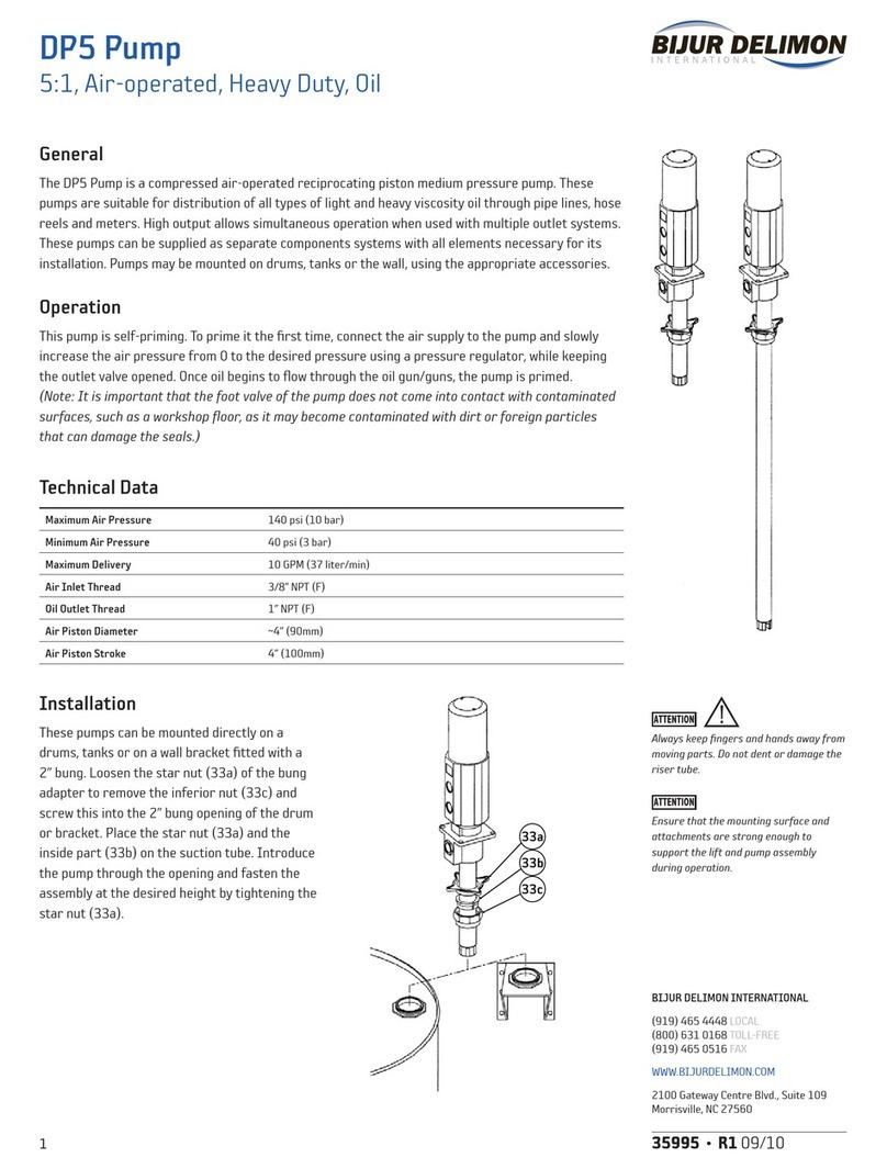
Separate the Air Motor from the Pump
1. Unscrew and remove the grease outlet adapter and the air inlet adapter. Remove the air
motor cover.
2. Mount the pump to a vise in horizontal position, securing it on the suction tube (47).
3. Unscrew the priming cylinder (60) from the priming filter head (57).
4. Unscrew the air motor body (15) from the suction tube (47) using a threaded rod or a pipe
wrench, and pull it out until it stops. The union nut (37) will be visible after cleaning the grease
from the rod.
5. Slide an open end wrench over the flats of the lower part of the air piston (36) and unscrew the
nut (59) and remove the washer (58).
6. Remove the large roll pin (38) located in the upper part of the union nut (37) and unscrew the air
motor body (15) from the suction tube assembly. (See drawing on right.)
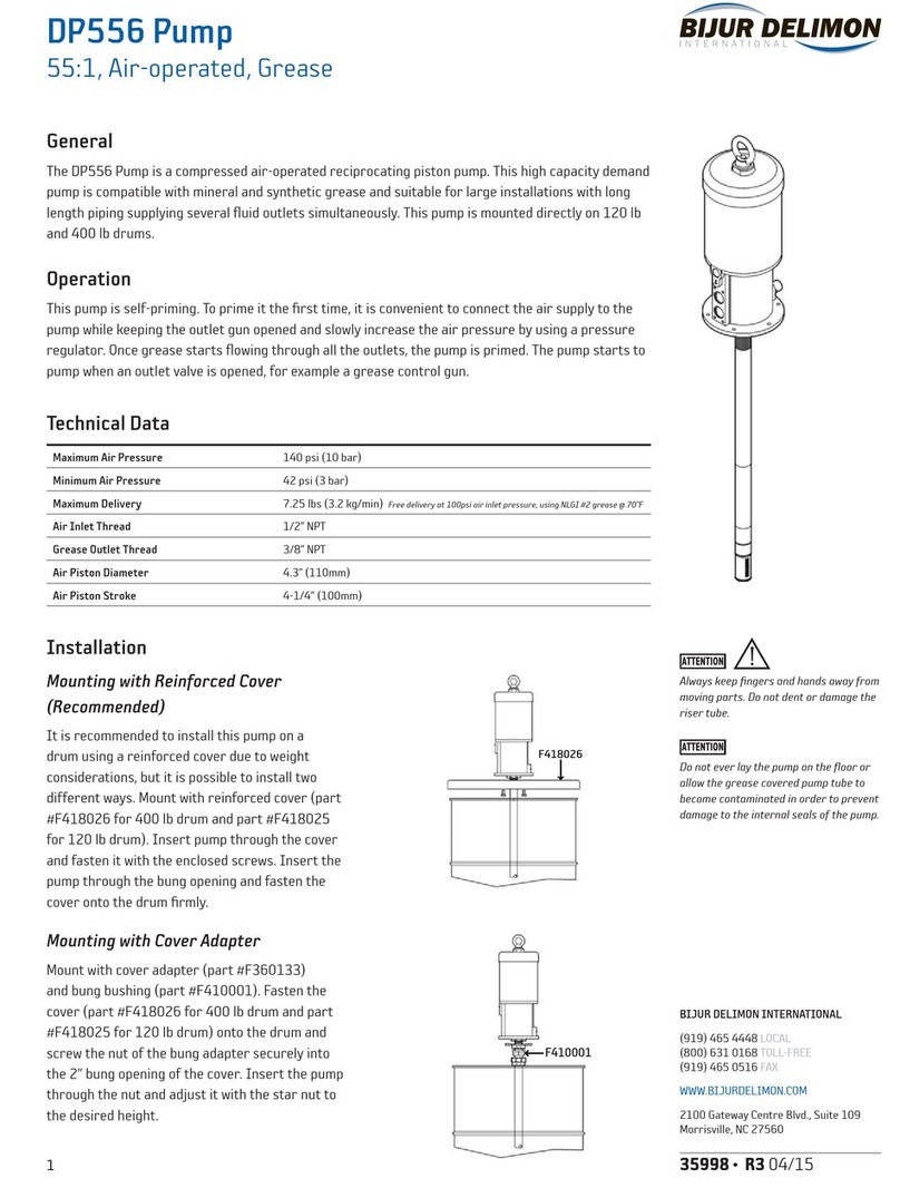
Foot Valve
1. Unscrew the foot tube (53) with the priming filter (57) from the high pressure cylinder (51).
Attach the foot tube to the vise, unscrew the priming filter (57), remove the foot valve seat (56),
the foot valve assembly (55) and the valve washer (54).
2. Clean these parts, replace if damaged. Assemble the pump following the previous instructions,
reversing each step. (Note the position of (55 and 56) on page 5 – the mating surfaces are
ground flat and the conical surfaces are opposed.)
Pressure Check Valve
1. Insert a steel rod (ø4mm recommended) through the lower grease by-pass hole in the high-
pressure piston (44) and unscrew it from the grease valve body (40).
2. Clean the check ball (43) and its seat in the high pressure piston (44). If damaged, replace all the
affected parts.
3. If the high pressure piston (44) is scored, unscrew the high pressure cylinder (51) from the
suction tube (47) and from the foot tube (53) and replace it. Assemble the pump following the
previous instructions, reversing each step.
Inverting Set and Air Motor
1. Secure the air motor body (15) and loosen the five 4mm screws (29) to remove the air
motor dolly (1).
2. Slide an open-end wrench over the flats of the lower part of the air piston (36). With second
wrench unscrew the air piston nut (2) and remove the parts (2-5).
3. Pull the air piston rod (36) down and out of the air motor body (15).
4. Unscrew the toggle nut (27) from the air motor body (15) and remove the parts (23-27).
5. Unscrew the 3mm allen screws (22) and remove the parts (16-21).
Packing Set and O-ring
1. Follow the procedure for the air motor until the air piston rod (36) has been removed from the
air motor body.
2. Remove the packing set (32-35) and the seal O-ring (31). Replace these parts and clean the seat
of the seal O-ring (31).
Refer to page 5 for parts reference.
Before starting any kind of maintenance
or repair, disconnect the compressed air
supply and open a downstream valve to
relieve the grease pressure.
The high-pressure piston and cylinder
must always be replaced at the same
time; they are a matched set.
It is important that the packing set and
O-ring are mounted in the correct order:
First locate the O-ring in the correct
position inside the motor body and use a
dab of grease to hold it in position. Then
install the large and small packing set.
Unscrew intake filter tube from intake
filter head
Unscrew air motor body from suction tube
Unscrew nut, remove washer
Remove pin, unscrew air motor body
PM3 Pump
55:1, Air-operated, Grease
