BIJUR DELIMON INTERNATIONAL
(919) 465 4448 LOCAL
(800) 631 0168 TOLL-FREE
(919) 465 0516 FAX
WWW.BIJURDELIMON.COM
2100 Gateway Centre Blvd., Suite 109
Morrisville, NC 27560
35998 • R3 04/153
Maintenance
Separate the Air Motor from the Pump
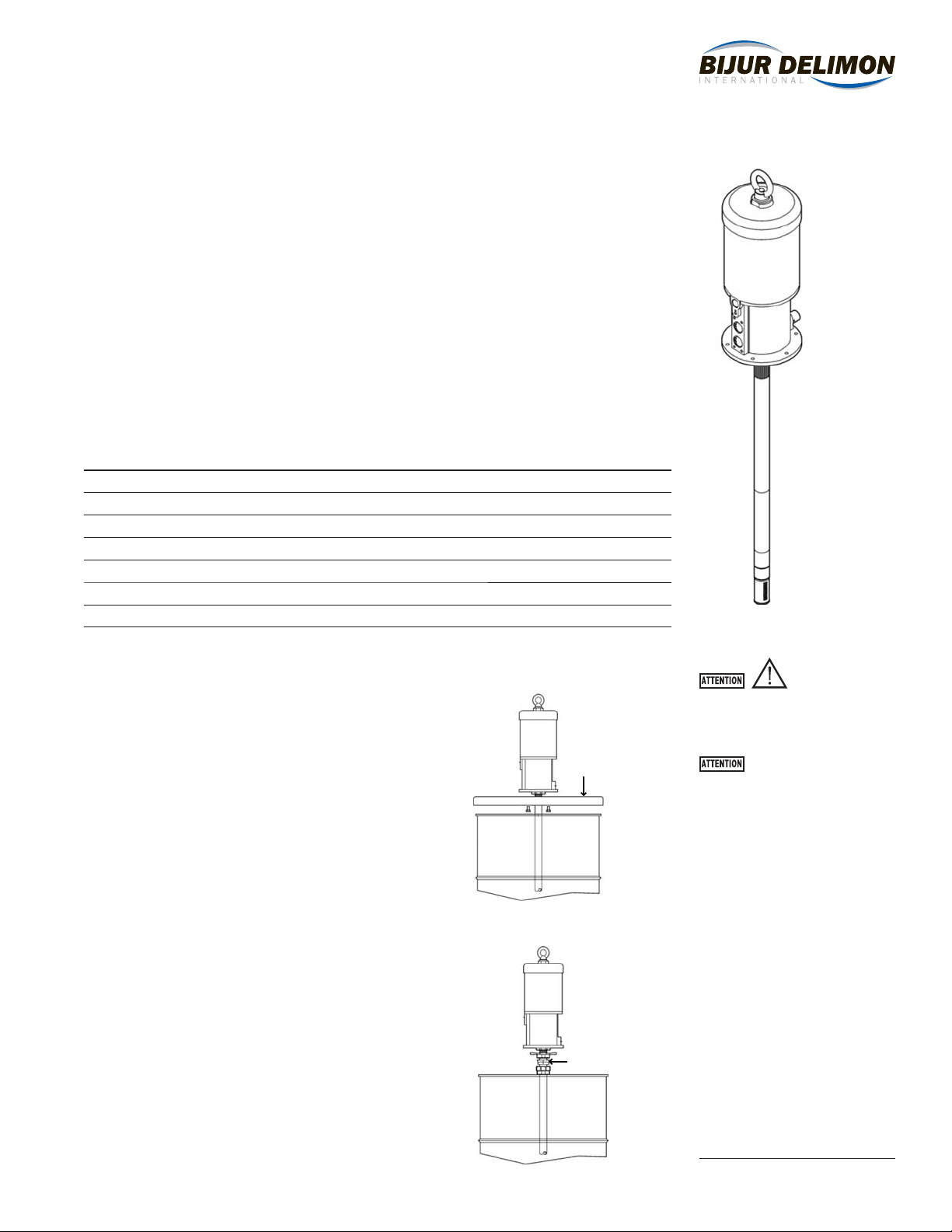
1. Secure the pump in a vice in the horizontal position, unthread the suction tube (53) from the
pump body (37) and pull out the tube until the pin (51) is visible.
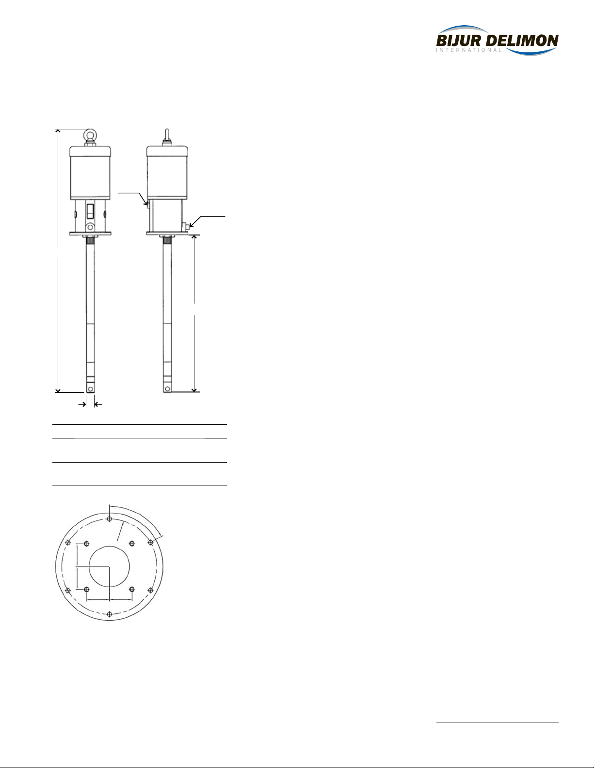
2. Remove the pin (51) and unscrew the connecting rod (52) until it is loose. (See drawing on right.)
Air Motor
1. Unscrew the lift ring (1) and the jam nuts (2) of the stroke end rod (3), remove the spacing
sleeve (4) and the closing ring (5).
2. Unscrew the air cylinder assembly (6) from the air motor body (37).
3. Remove the circlips (29) and push the trip shoe spring (28) backwards.
4. Remove the spring seat (8), the inverter assembly and the trip shoes (26).
5. Unscrew the screws (13) and the nuts (17) and disassemble all the parts until the air gasket (23)
becomes accessible.
6. Take out the air piston assembly and the seals (31, 34).
7. Clean all the parts and replace if necessary. Lubricate the components with grease and assemble
the pump following the previous instructions, reversing each step.
Replace the Packing Set
1. Follow steps 1 through 6 of the air motor maintenance procedure.
2. To unscrew the outlet adaptor (40); thread a 3/8” fitting completely into the adaptor and pull
clockwise first to break the seal, then counter clockwise to loosen and remove it, or use a
pipe wrench.
3. Unscrew and remove the packing set from the air motor body.
4. Replace the packing set with a new one. Mount the outlet adapter using Loctite Red sealer on
its threads.
5. Clean and lubricate the air motor components carefully. Assemble the pump following the
previous instructions, reversing each step.
Clean or Replace the Upper Valve
1. Unscrew the suction tube from the foot valve tube (60), remove the pins (51) and unscrew the
connection nut (54) from the piston (57).
2. Clean the balls (55, 56) and the housing carefully.
3. Verify the piston (57) and the high pressure cylinder (59) for scratches/scoring and the o-ring
(58) for damage; replace if necessary. Assemble the pump following previous instructions,
reversing each step.
Clean or Replace the Foot Valve
1. Unscrew the nut (72) and remove the filter (71), unscrew the nut (70) from the priming rod (67)
and remove the primer (69).
2. Push the rod (67) inwards and unscrew the priming tube (68) from the foot valve tube using the
provided holes.
3. Take out the parts of the valve (62-65) and clean them carefully, replace if damaged. Assemble
the pump following previous instructions, reversing each step.
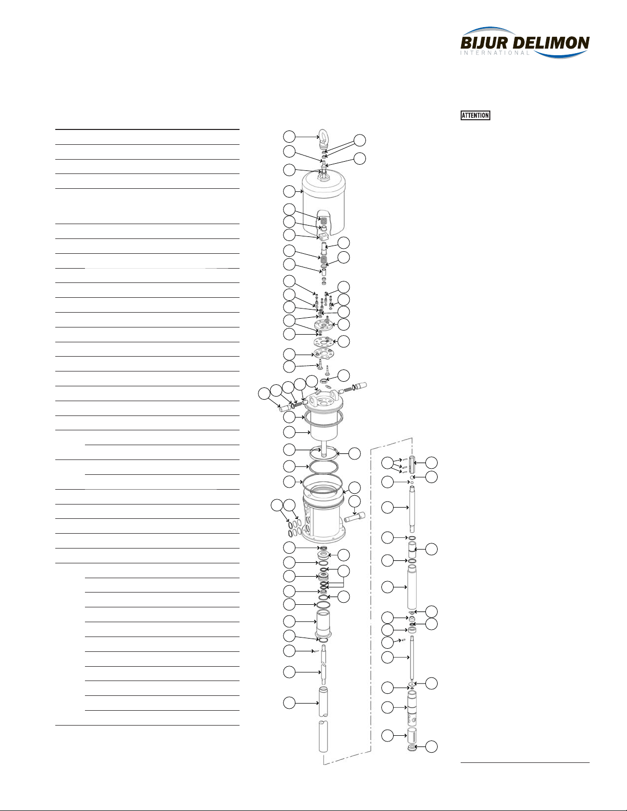
Refer to page 5 for parts reference.
Before starting any kind of maintenance
or repair, disconnect the compressed air
supply and open a downstream valve to
relieve the oil pressure.
Remove pin and unscrew connecting rod