Bike Fixation Bicycle Access Ramp User manual

BICYCLE ACCESS RAMP INSTALLATION INSTRUCTIONS
Customer Service
800.783.7257
bikefixation.com

3
Tell Us What You Think
bikefixation.com/bicycleaccessramp
Register your product for updates
bikefixation.com/registration
Thanks for buying our Bicycle Access Ramp!
You’re now the proud owner of the Bike Fixation Bicycle Access Ramp, a modular ramp system designed for users to
easily transport their bikes up and down stairs.
The Bicycle Access Ramp is made in the USA, and features an aluminum ramp channel. The stock length of channel is
8 feet. The channel is easily cut to length. For installations up to 16 linear feet, two sections of the channel are used.
The second channel is cut to size and attached to an uncut 8’ section of ramp using the joining biscuit assembly.
High strength aluminum end cap modules are provided with the system. They bolt on to the ends of the ramp and pro-
vide a smooth transition on and off the Bicycle Access Ramp.
The Bicycle Access Ramp is attached to the stairs using a mounting bracket system. The mounting brackets pivot,
allowing a wide range of stair pitches to be accommodated. Brackets are bolted onto the stairs. Concrete anchors are
provided with the system. If mounting to materials other than concrete, use an appropriate fastener for the base mate-
rial. Brackets are sized to accept ¼” fasteners.
Please read and understand these instructions before beginning installation.
Everyone here at Bike Fixation and our endorser brand, Saris, want you to be happy with this product. Please contact us
Now, let’s get started.
4 5
Tools Needed
9/16” socket
7/16” socket
Ratchet
9/16” Open/box End
Wrench
Hammer drill with 3/8”
masonry bit
Hammer
¼” Anchor set tool
(included)
Mallet
Chop Saw w/ 3x6.5”
capacity
& cutting blade for alumi-
num
Tape Measure
File or sanding tool
Torque Wrench
Materials
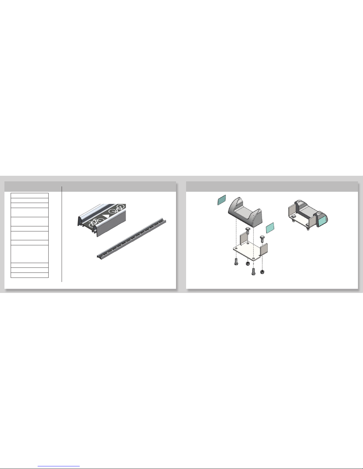
Ramp Module (8’ stock length)
Materials (cont)
End Cap Module
note: module includes 2 end caps
Figure 1 Figure 2
6 7
Joining Biscuit Module
Materials (cont)
Mounting Bracket Module
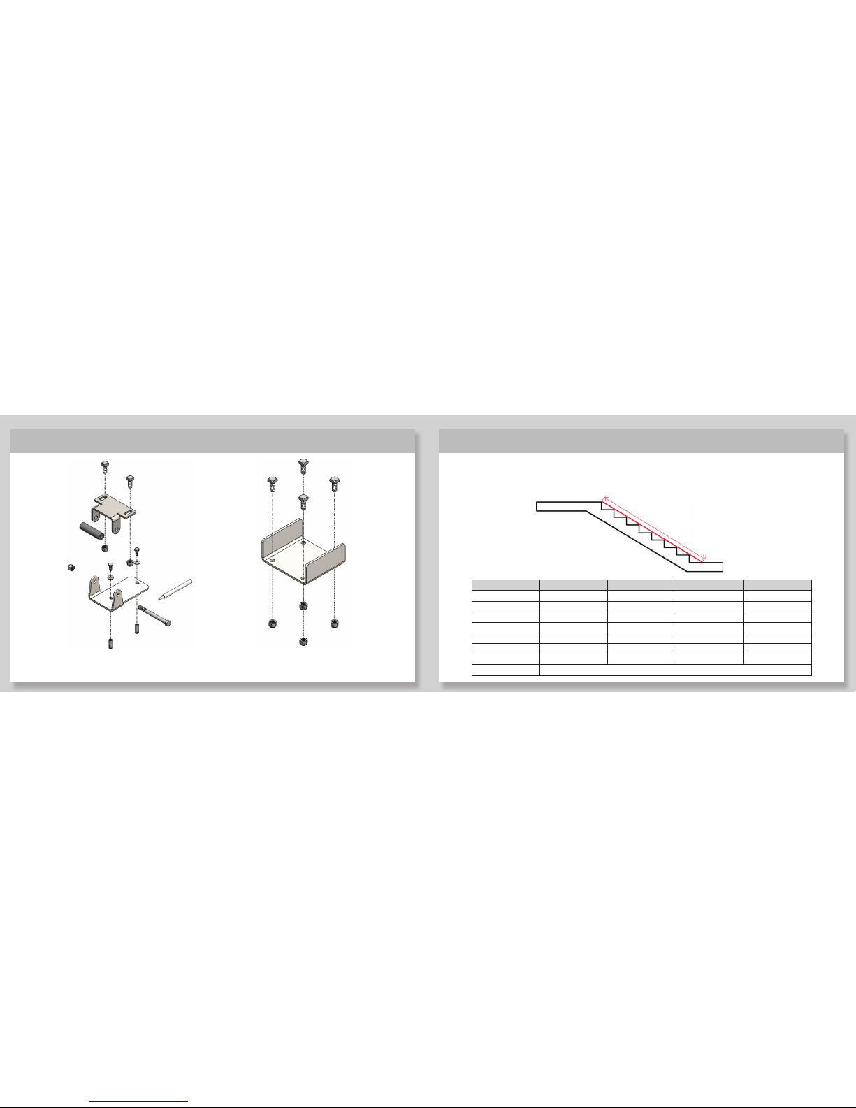
The table shows how many modules are required for various installation lengths. DOUBLE CHECK ALL INSTALLATION
LENGTHS BEFORE BEGINNING INSTALLATION. IF REQUIRED INSTALL LENGTHS ARE SIGNIFICANTLY DIFFERENT (OVER 1
FOOT DIFFERENCE) THAN QUOTED FOR YOUR ORDER PLEASE CONTACT BIKE FIXATION.
Installation Length # of Ramp Modules # of End Cap Modules # of Bracket Modules # of Joining Modules
4 to 8’ 1 1 3 0
8 to 12’ 2 1 4 1
12 to 16’ 2 1 5 1
16 to 20’ 3 1 6 2
20 to 24’ 3 1 7 2
24 to 28’ 4 1 8 3
28 to 32’ 4 1 9 3
Over 32’ Contact Bike Fixation
Installation Length
Figure 3 Figure 4 Figure 5

8 9
Instructions
Cut ramp to length. Verify installation length. Subtract 5” from this measurement. This is the total length of
ramp required for the installation. (This accounts for the addition of the end caps onto the ramp).
For installation lengths of less than 8’5”, this means the 8’ ramp section should be cut to size. For example, a 7’0”
installation length would require the ramp section to be cut to 6’7”.
For installation lengths longer than 8’5” you will use one uncut 8’ ramp and cut one 8’ section to size. For example,
the 12’10” installation length requires a total ramp section of 12’5”. One ramp would be cut to 4’5” and be used
with an uncut 8’ ramp.
Mark ramp at desired cut length. Cut ramp using chop saw with a blade appropriate for cutting aluminum.
Sand or file all cut edges to remove burrs.
1Connect ramp sections using joining biscuit module. (Not required for installations less than 8’5”).
Loosely fit 2 of the square head bolts on the joining biscuit into the slots on the uncut ramp section. Place the uncut
edge of the shorter ramp section against the first ramp section to ensure the grip tape pattern lines up. Place join-
ing biscuit into second ramp section. Position biscuit so that it’s approximately centered between the two sections.
A minimum of 1” of biscuit overlap is required. Tighten 3/8-16” nuts to 25 ft-lbs.
Install additional ramp sections and joining biscuits as needed to build the full length of ramp.
2
Figure 6

10 11
Slide mounting brackets onto ramp section. Place square head bolts on mounting bracket modules into
slots on ramp. Orient brackets as shown. On very shallow stairs (less than 20%), brackets orientation may need to
be reverse. Position end brackets approximately 6 to 12” from end of ramp, and tighten nuts until bracket is snug
but can be moved along the length of the ramp. Position additional brackets approximately every 4 feet and snug
into place.
3Install end cap modules onto ramp ends. Insert end caps into end of complete ramp section. Slide square
head bolts into slots on ramp. If necessary, use mallet to position end caps flush with the edge of the ramp. Tighten
3/8-16 nuts to 25 ft-lbs
4
Figure 8Figure 7 Figure 9

12 13
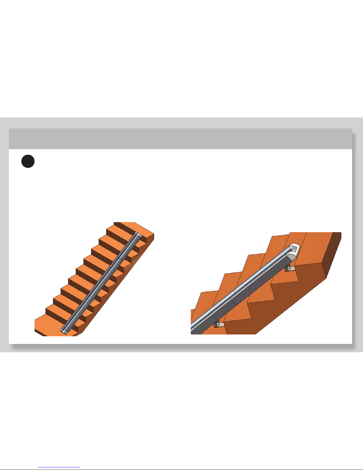
5Set ramp spacing from wall/edge. Place the edge of the ramp assembly 6 inches from the adjacent wall or
edge of stairway.
7
Place ramp assembly on stairs. The bottom endcap should rest on the floor/landing. The bottom mounting
bracket should lie on the floor at the bottom of the steps. The top mounting bracket should lie on the stair tread just
below the top of the stairway. The bottom edge of the ramp should rest along the leading edges/nose of the stairs.
The other mounting brackets should be positioned so that they are approximately 3 to 4 linear feet from the next
mounting bracket(s). If stairway does not allow even placement between brackets, position them such that there is
no more than 4 linear feet of unsupported ramp along any portion of the ramp.
Prepare bracket assembly. Position the bracket
assemblies so that the ramp bracket is snug against the
ramp and the stair tread bracket lies flat on the ground/tread.
Snug the brackets onto the ramp.
6
Figure 10 Figure 11

14 15
8Install stair tread anchors.
Make sure that ramp is positioned on stairway as desired. Ramp should run parallel with wall. The bottom end cap
should be flush with the floor/ground/landing. Make sure that all stair tread brackets are lying flat on treads and
that ramp brackets are tightened to ramp. Make sure bottom of ramp is less than 3/8” away from the leading edges
of stairs. Ideally the ramp is flush against the edge/nose of every stair.
Mark the position of the stair tread bracket on the stair tread.
Remove the ramp assembly from the stairway.
Remove one of the stair tread brackets by removing the pivot hardware (3/8-16x4” bolt, nut, and spacer). Use the
stair tread bracket as a template to mark the position of anchors. Qty (2) ¼’ anchors are used per stair tread brack-
et. Note orientation of tread bracket when marking anchor locations.
Using hammer drill and 3/8” masonry bit, drill holes 1 1/16” deep. Install anchors per Figure 12. See https://embed.
widencdn.net/pdf/plus/ssttoolbox/p5gi8x8lsl/F-A-DIAB15.pdf?u=cjmyin for further detail on anchor installation and
specifications. Anchors and anchor set tool are included.
Figure 12
16
9Install ramp assembly onto stairs
Reinstall stair tread bracket(s) as needed. Position the ramp assembly onto the stairs. Loosely install ¼” hex head
bolts and washers into stair tread brackets. Verify fit of ramp on stairs.
Tighten stair tread mounting bolts using 7/16” socket/wrench to 5 to 7 ft-lbs. Tighten mounting bracket pivot nuts
and bolts to 25 ft-lbs. Verify that all ramp bracket bolts are tightened to 25 ft-lbs.
Figure 13 Figure 14
Table of contents


