RPE GSX-R 1300S User manual

Radical Performance Engines GSX-R Engine Operation Manual
Version 4 - 18.12.14

Specifications ..........................................................................................1
Installation ..............................................................................................1
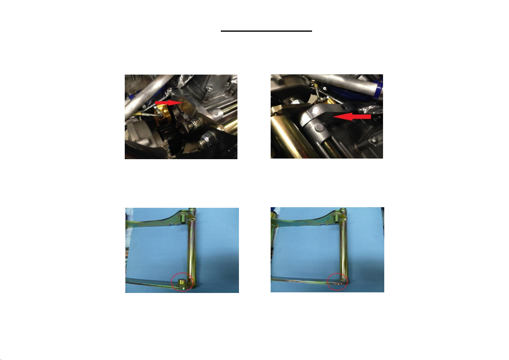
Rear Engine Brace ...............................................................................1
Oil System................................................................................................1
Coolant System ...................................................................................1
Fuel......................................................................................................1
Octane Boosters..................................................................................1
RPE –Quaife Gear Drive System.........................................................1
Types of Oil Systems ...............................................................................1
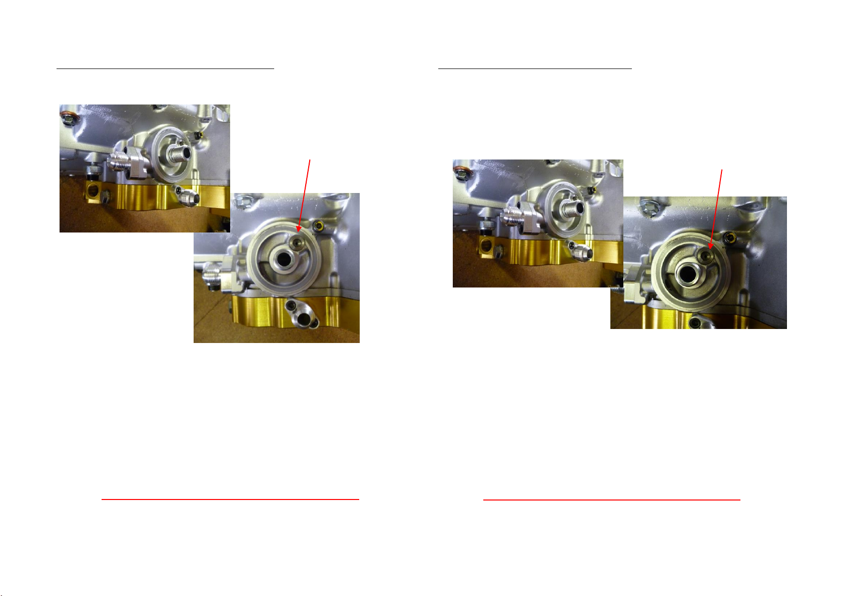
Oil Type Number 1 - Blanking Plates, No Jet.......................................2
Oil System Number 2 - Oil cooler fittings and jet ...............................2
Oil System 3 –Oil Cooler Fittings and Bung........................................3
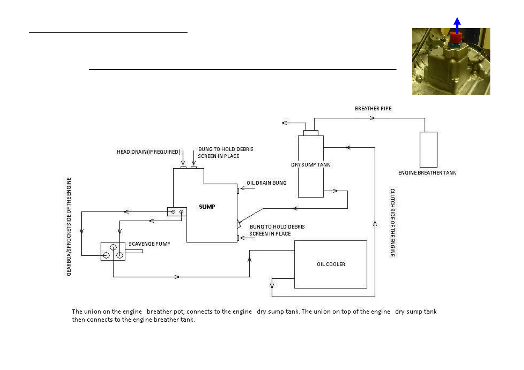
Oil System 1 Diagram - Cast Sump Pan……………………………………………5
Oil System 1 Diagram - Billet Sump Pan…………………………………..………6
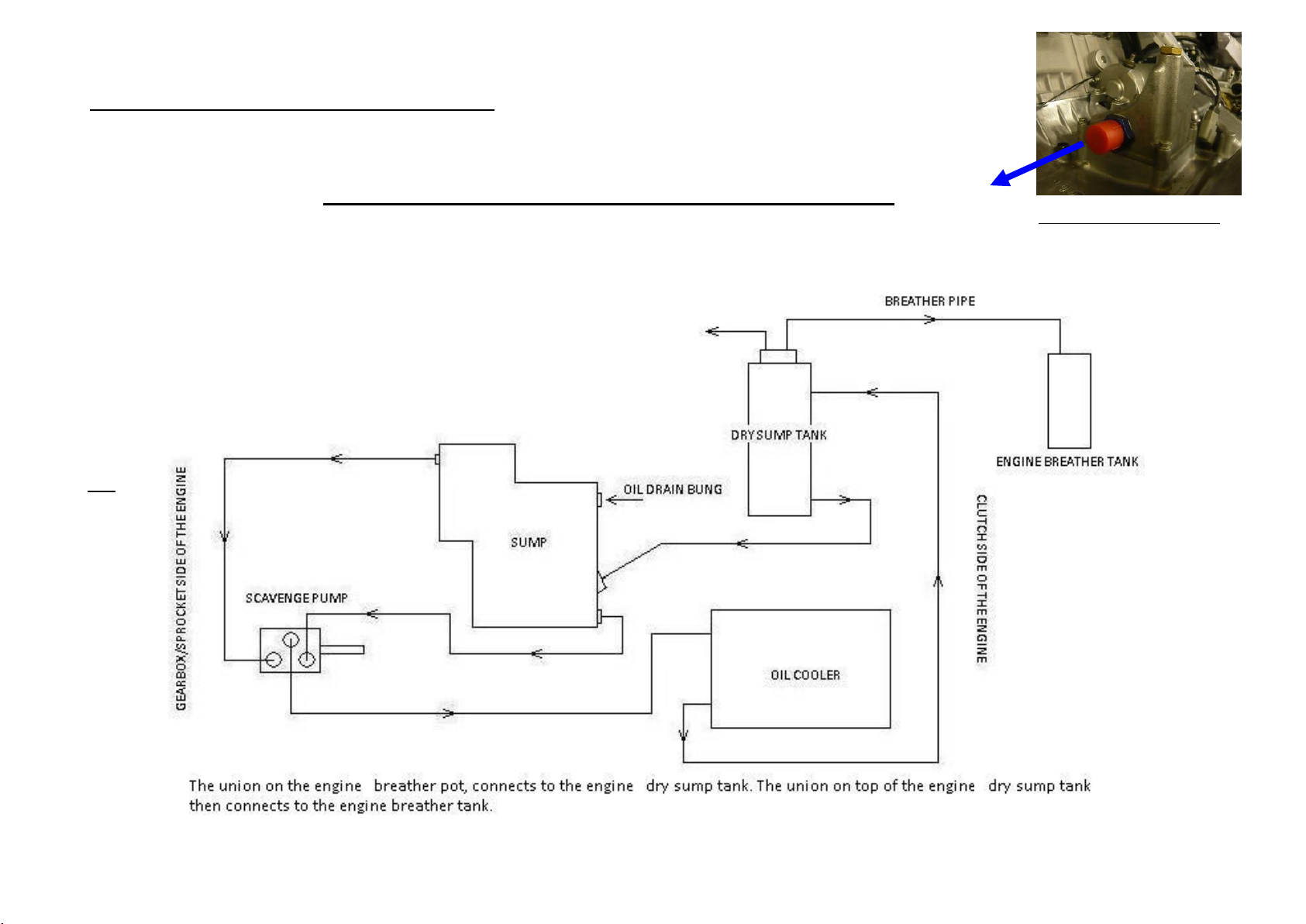
Oil System 2 & 3 Diagram…………………………………..…………………………..7
Engine Management...............................................................................7
MBE - Radical Easimap Setup Screen..................................................7
Life Racing - PTMon.............................................................................7
Throttle and Airbox installation..............................................................8
Airbox..................................................................................................8
Fluid Levels and Temperatures...............................................................8
Coolant Temperature..........................................................................8
Coolant Level.......................................................................................8
Oil Temperature –both Wet and Dry Sump Systems.........................8
Wet Sump Oil Level.............................................................................8
Dry Sump Oil Level ..............................................................................8
Starting Procedure……………………………………………………………………………10
Re-Starting ..........................................................................................9
Service Intervals......................................................................................9
Engine Oil and Oil Filter ...................................................................... 9
Oil Filter Fitting Procedure .............................................................9
Fuel Filter............................................................................................ 9
Air Filter ..............................................................................................9
Engine Returns...................................................................................... 10
Balancing Throttle Bodies on a 4 cylinder ............................................11
Life Racing ECU .................................................................................11
MBE ECU...........................................................................................12
Instructions For Retrieving Data from Life ECU and Data logger.........13
Driving Techniques for Cars with an RPE Engine..................................14
Contact Details...................................................................................... 15
Contents

1
Specifications
•GSX-R 1300S
•GSX-R 1300T
•GSX-R 1350T
•GSX-R 1340T
•GSX-R 1400T
•GSX-R 1500
•GSX-R 1550T
•GSX-R 1585T
•GSX-R 1600T
•GSX-R 1300 Turbo
•GSX-R 1615T
•GSX-R SS 1500
Rated Speed –10,500 rpm
Firing Order –1, 2, 4, 3.
Cylinder 1 is on the left hand side of the engine (Generator side).
Installation
The engine should be mounted into the chassis by means of four bolts into
the mounting points on each side of the cylinder head and two bars through
the horizontal rear mountings in the crankcases above and below the
gearbox through the rear engine Brace. See next Page for Rear Engine Brace
fitting procedure.
Ensure no looms or hoses are trapped between the engine and chassis.
All sensors should be connected correctly and in working order, including:
•Air charge temperature
•Crank Position Sensor
•Oil pressure
•Fuel Pressure (if applicable)
•Coolant temperature
•Throttle Position Sensor
•Oil temperature
•Barometric sensor
•Cam Phase Sensor (if
applicable)
The oil system must be connected as per the information in this operation
manual. Please read this document carefully, there are different types of oil
system fitted to RPE 4 cylinder engines. Please ensure the correct oil system
is used. There is more information on the various oil systems on pages 2 to 7.
PLEASE BE AWARE THAT FITMENT OF AN INCORRECT OIL
SYSTEM COULD CAUSE AN ENGINE FAILURE AND WILL
INVALIDATE YOUR ENGINE WARRANTY.
The coolant system must be connected and capable of providing adequate
cooling to maintain the correct operating temperatures outlined later in this
document.
Please contact RPE if you have any questions concerning the installation of
your engine. Contact details are listed on page 16.

1
REAR ENGINE BRACE
Dear Radical owner, mechanic or distributor,
Your engine has been returned with a supporting brace on the rear of the engine:
In order to fit your engine you will need to modify the rear engine cradle by removing a boss as shown:

1
Oil System
Recommended –Silkolene PRO R or PRO 4 15W-50
PRO R/4 is a unique, fully synthetic lubricant for ultimate engine protection
and superior clutch and gearbox operation for high performance 4 stroke
motorcycle engines.
If this specific oil is not available to you, please use a comparable
oil.
NEVER USE CAR ENGINE OIL IN A MOTORCYCLE ENGINE. THE INTEGRAL
GEARBOX WITHIN THE MOTORCYCLE ENGINE WILL SHEAR THE MOLECULES
IN THE OIL. ALSO, MOTORCYCLE ENGINES HAVE INTEGRAL WET CLUTCHES.
Coolant System
50% water and 50% antifreeze/summer coolant.
Fuel
RPE Suzuki engines should be run on a minimum of Super Unleaded 98 RON,
or 100 octane race fuel.
Tuned engines in the USA should be run on racing fuel such as Cam2 or a
minimum of 108 Octane.
Octane Boosters
If fuel of the correct octane level is not available then octane boosters can be
used, please contact RPE before using octane boosters in fuel.
RPE –Quaife Gear Drive System
Recommended Oil –Shell Helix Racing Gear Oil 75W-90
Shell Helix Racing Gear Oil 75W-90 is a synthetic gear oil designed to provide
optimum protection under extreme load conditions, whilst maintaining high
efficiency.
Oil Systems Variations
Due to a number of different oil cooling systems in circulation, the oiling
system must be confirmed before the engine is installed.
Oil System Number 1: 2 blanking plates installed on the engine oil cooler inlet
and outlet ports and the oil jet behind the oil filter is removed.
Oil System Number 2: -8 or -10 oil cooler fittings on the engine oil cooler inlet
and outlet ports, and the oil jet behind the oil filter has a 3mm hole drilled in
it.
Oil System Number 3: -8 or -10 oil cooler fittings on the engine oil cooler inlet
and outlet port. A blanking bung is installed behind the oil filter, in place of
the oil jet.
•On later model engines, that are fitted with a cast type sump pan,
there is only one type of oil system regardless of installation. One
blanking plate on the oil cooler inlet port and the oil jet behind the oil
filter is removed.
•If you are unsure as to the specification of your previous engine, RPE
can provide you with the necessary information.
•An RPE technician can also confirm the specification for you if an
engine exchange is to take place at a race meeting.
•If in any doubt please Phone or Email
Tel +44 (0)1733 331919
Email info@radicalperformanceengines.com or
technical1@radicalperformanceengines.com
Fluids

2
Oil Type Number 1 - Blanking Plates, No Jet
This type of oil system can be used with both RPE cast (Silver) and billet
(Gold) dry sump pans.
The restrictor jet behind the oil filter is also removed. The oil return pipe
from the scavenge pump goes through the oil cooler (or water to oil heat
exchanger) before returning to the oil tank.
Cast Sump
Jet Location
If the engine is fitted with a cast sump pan, there will be no blanking plate on
the sump pan, just one on the engine.
Billet Sump
Jet Location
Blanking plates are fitted to the engine’s OEM oil cooler in and outlet ports.
IMPORTANT
When this oiling system is used, the jet behind the filter must be removed.
IF THIS IS NOT DONE IT WILL RESULT IN ENGINE FAILURE.

3
Oil System Number 2 - Oil cooler fittings and jet
This system can only be used with RPE billet dry sump pans.
Jet with 3mm diameter hole
There are two fittings on the engine oil cooler inlet and outlet ports, they are
either -8 or -10. In this case there is a restrictor jet with a 3mm hole located
behind the oil filter. The oil returning from the scavenge pump is pumped
directly back to the oil tank.
IMPORTANT
When using this oiling system, the jet behind the filter must have a hole
drilled in it.
IF THIS IS NOT DONE IT CAN RESULT IN ENGINE FAILURE.
Oil System 3 –Oil Cooler Fittings and Bung
This system is mainly used on the Radical SR4, as they have long hoses that
run to and from the oil cooler due to the radiator being mounted further
away from the engine than normal
Blanking Bung
There are two fittings on the engine oil cooler inlet and outlet ports, they are
either -8 or -10. In this case there is a blanking bung behind the oil filter. The
oil returning from the scavenge pump is pumped directly back to the oil tank.
IMPORTANT
When using this oiling system, the jet behind the filter has no hole drilled, it
is a solid bung.
IF THIS IS NOT DONE IT CAN RESULT IN ENGINE FAILURE.

4
Oil System 1 Diagram –Cast Sump Pan
Breather Pot Connection
To dry sump tank
FROM UNION ON TOP OF
ENGINES BREATHER POT
Radical Performance Engines GSX-R Oil System –2008 Onwards
This is for an RPE Hayabusa Engine with a cast sump pan.

5
FROM UNION ON TOP OF
ENGINES BREATHER POT
Oil System 1 Diagram –Billet Sump Pan
Breather Pot Connections
To dry sump tank
Radical Performance Engines GSX-R Oil System
This is for an RPE Hayabusa Engine with a billet sump pan.
FROM UNION ON TOP OF
ENGINE BREATHER POT

6
Oil System 2 & 3
To engine breather tank
To dry sump tank
This is for an RPE Hayabusa engine with a billet sump pan.
Radical Performance Engines GSX-R Oil System –Pre 2008
Radical Performance Engines GSX-R Oil System Pre 2008
This is for an RPE Hayabusa Engine with a billet sump pan.
Breather Pot Connections

7
Engine Management
Most RPE engines will either use MBE or Life Racing engine management. The
pictures below show the monitoring programs which should be loaded on a
laptop that is connected to the ECU each time the engine is started.
MBE - Radical Easimap Setup Screen
1) Engine RPM –(Engine should idle between 1500 and 1800rpm)
2) Throttle Position Sensor –(set at 0.18V at idle)
3) Barometric pressure
4) Coolant Temperature
5) Oil Pressure
6) Oil Temperature (Minimum of 45°C, Maximum 120°C)
7) Battery Voltage
8) Air Inlet Temperature
Life Racing - PTMon
1) Engine coolant temperature (ect1) –changes from red to green when in
correct range of 60 oCto 95 oC
2) Engine oil temperature (eot) –changes from red to green when in correct
range of 50 oCto 120 oC
3) Engine oil pressure (eop1) –At idle, 70 psi when cold /20 psi when hot
4) Engine rpm (rpm) –Engine should idle between 1500 and 1800rpm
5) Throttle position sensor (tps1) –needs to be set to 4% at idle
6) Engine sync state –should be at 720 when engine is running, turns green
when correct
7) Fuel pressure (fp1) –changes from red to green when in correct range of
2.8 bar to 3.2 bar
8) Battery voltage (vbat) –above 12.5 volts when engine is running
9) Air charge temperature sensor (act1) –air inlet temperature
10) Engine ECU temperature (btMax) –temperature of the engine ECU
11) Baro sensor pressure (bap) –below 1030 mBar
1
2
3
4
5
6
7
8
0.19
6
7
8 9 10 11 12

8
12) Gear Indicator –Should be Neutral when starting. Gear position voltage
displayed for technical use
Throttle and Airbox installation
Airbox
Ensure that all fixings on the air box are tight and there are no foreign bodies
that could fall into the engine and cause damage once the engine has been
started. All bolts/screws in the airbox must be lock wired or fixed using
thread lock.
Fluid Levels and Temperatures
Coolant Temperature
When the engine is on track, the coolant temperature should be between
70°C and 90°C.
Coolant Level
When the system is fully bled, the coolant should be full to the top of the
swirl pot, and there should be a minimum of 10 to 20mm in the coolant catch
pot.
Oil Temperature –both Wet and Dry Sump Systems
When the engine is on track, the oil temperature should be between 90°C
and 115°C.
Wet Sump Oil Level
The procedure for checking the oil level is as follows. This should be done
with the car on level ground.
With the engine running and the coolant up to 50°C, hold the revs at 3000
rpm. There should be no bubbles in the sight glass, from 3000RPM, blip the
throttle and an air bubble should appear in the sight glass.
The sump is baffled and the oil takes some time to settle.
Dry Sump Oil Level
For cars fitted with a dry sump system the oil level must be checked using the
dip stick supplied. The dry sump oil tank level must be maintained at the TOP
mark on the dipstick with the engine as close as possible to the
recommended on track running temperatures (See Fluid Levels and
Temperatures opposite). The bottom mark is only used when the oil is cold.
The level should be checked AFTER running the engine up to temperature
and after holding the revs at 4,000rpm for ten seconds, to allow the oil to be
scavenged back to the oil tank. The engine should be turned off to check the
level. (The sight glass in the side of the engine should be ignored).
If you do not have the correct dipstick for checking your dry sump tank,
contact a member of the Radical Parts Department immediately. Their
contact details are on page 16.
Dipstick being used to check oil level in a Radical SR3

9
a. Always start the engine with a laptop connected to the ECU so that all
engine parameters can be monitored during warm-up. This also confirms all
the vital engine sensors are working.
b. Check plenty of oil is visible in the oil tank and the coolant level is to the
top of the swirl pot.
c. The engine should be dry cranked, some oil will have drained back into the
engine if it has been previously run. This will return to the tank once the
engine is started. To dry crank the engine, disconnect the ignition coils and
turn the engine over until it produces oil pressure and oil is returning to the
oil tank.
d. Once the engine is producing oil pressure and the oil is returning to the
tank, re-connect the ignition coils and turn the ignition on. Start the engine
with no throttle, then increase the engine speed to approximately 2,000rpm
–3,000rpm. Check the oil pressure - it should be a minimum of 60 psi.
e. When the engine coolant temperature reaches 50°C, hold the engine revs
at 4,000rpm for a few seconds (this allows the scavenge system to clear oil
from the crankcases) and turn the engine off.
WARNING –RADIATOR COOLING FANS ARE NOT FITTED AS STANDARD. DO
NOT LET THE WATER TEMPERATURE EXCEED 90°C WHEN WARMING THE
ENGINE TO CHECK THE OIL LEVEL.
f. Immediately check the oil level, it must be between the top two marks on
the dipstick.
Re-Starting
a. Ideally, the engine should be started 45 minutes prior to going on track.
Turn the engine off when the coolant temperature reaches 85°C and allow
heat to soak into the engine. Restart 10 minutes before going on track and
get the coolant temperature to 75°C.
b. The oil level should be checked after every hour of running, and it should
be topped up to the level indicated in these instructions.
Service Intervals
Engine Oil and Oil Filter
The engine oil and filter should be changed after every 5 hours of running.
Oil Filter Fitting Procedure
1) Apply a thin film of engine oil to
the sealing o-ring on the oil filter.
2) Screw the filter on to the engine
by hand, until the o ring on the oil
filter contacts the engines surface.
3) Using an oil filter tool (shown in
picture), turn the filter another 2 turns.
4) To prevent the oil filter coming loose
during operation, a jubilee clip must be
fitted around the oil filter. The adjuster
screw housing of the jubilee clip should sit
against the bolt in the crankcases, as
shown in the picture. It should be located
hard up against the right hand side of the
bolt, as you look directly at the oil filter. If it is on the wrong side, it will not
effectively prevent the oil filter from coming loose.
Fuel Filter
The fuel filter should be cleaned after every 20 hours of running or visually
inspected - especially if you have recently fitted a new fuel tank, are
experiencing fuel starvation, or a drop in fuel pressure.
Air Filter
The engines air filter should be inspected before every race. It should then be
cleaned and oiled as per the manufacturer’s instructions and should be
replaced as required.
Starting Procedure

10
Engine Returns
When returning an engine to RPE for a refresh or repair, the engine should be
removed from the vehicle and be externally clean. Please follow the
procedure below.
•Flat packed metal crates can be collected from your local distributor,
alternatively you can drop off your engine at your distributor and
they will process the engine on your behalf.
•All engines must be drained of fuel, coolant and oil.
•Tilt the engine, so that the drain bung on the sump is the lowest
point of the engine and leave for 3 to 5 hours.
•Bung all oil, water and fuel inlets and outlets.
•If possible shrink wrap or seal the bottom end of the engine to catch
any residual fluids.
•Ensure no previous shipping details remain on the shipping container
as this may cause delays with shipping and customs.
•Locate the engine securely in a crate.
•Add packaging to secure the engine.
•Additional items (ECU, throttle bodies etc) must be packaged and
secured.
•Secure lid and affix address labels to lid and side of crate (minimum
of 2 labels)
To keep within the warranty rules, the ECU should always be returned to RPE
with the engine. This is for two reasons:
•Data can be checked.
•Engine hours can be reset on the ECU.
In the event of an engine failure:
•RPE should be contacted and the ECU’s data should be downloaded
and e-mailed to Radical Performance Engines technical: ………………..
(technical1@radicalperformanceengines.com).
•Debris may have transferred to the oil lines and cooler. An exchange
oil cooler MUST be fitted and the oil lines flushed thoroughly with
non-water based cleaner (Such as Petrol or Jizer cleaning fluid). The
cooler can be purchased either from Radical Performance Engines or
your local Radical distributor. If in good condition, you will only be
charged the cost for ultrasonically cleaning your exchange oil cooler.
Failure to carry out the above will result in your engine warranty being void
and no claim can be made against it.
As soon as your original engine is repaired and fully refreshed you will be
credited/invoiced for the work/parts required.
RPE do not cover the cost of removal and refitting of the engine, any third
party costs or replacement of fluids.
RPE also offer a range of optional services when having your engine rebuilt.
These are:
•Injector testing and cleaning
•Heat exchanger strip and clean
•Oil cooler ultrasonic cleaning

11
Balancing Throttle Bodies on a 4 cylinder
Life Racing ECU
1) Connect a laptop to the car and load PTMon. (This displays the engine
sensor readings)
2) To achieve a base setting the throttle needs to be fully closed. To ensure it
is, wind the idle adjuster screw out whilst watching the TPS reading
displayed in PTMon. The value should reduce as you wind the screw out.
Once the value stops reducing, the throttle is fully closed.
3) Set the TPS value to 2.0. To do this, loosen the TPS using a 3mm allen key, as
shown in the picture. Once loose, turn the TPS until its value shown on
PTMon is 2.0, and re-tighten the securing screws.
4) Using a 3mm allen key turn the idle adjuster screw, until the TPS
value is 4.0.
5) Now you are ready to start the engine. Check the engine oil, water and
electrical connections. (Especially if it is a new engine installation). Once you
have confirmed these are OK, start the engine and let it idle. Make sure the
engine temperature is maintained within its operating parameters. Do not
allow the water temperature to rise above 90°C.
6) Place the syncrometer in throttle body number 3. This body is not
adjustable it is your base which the rest of the bodies need to match. The
syncrometer will normally read between 5 and 7.
7) Place the syncrometer in the other bodies, using a 7mm spanner and 2mm
allen key (as shown in the picture below) adjust the other bodies to match
the reading from body number 3. Please note that turning the adjuster
clockwise opens the body. To adjust, loosen the 7mm nut and turn the
adjuster in the centre. Once the reading is correct, lock off the adjuster by
tightening the 7mm nut and holding onto the 2mm allen key to stop it from
moving. When balancing match the reading on cylinder 3 and 4 with the
adjuster, then match 1 and 2 finally use the centre adjuster to match both
sides.
8) Once all four bodies give the same reading on the syncrometer, the bodies
are balanced. Give the engine a couple of small blips and check the TPS
value returns to 4 and all the throttle bodies read the same on the
syncrometer.
TPS
Idle adjuster
screw
TPS Adjuster Screws
1
2
3
4

12
MBE ECU
1) Connect a laptop to the car and load Easimap. (This displays the engine
sensor readings)
2) To achieve a base setting the throttle needs to be fully closed. To ensure it
is, wind the idle adjuster screw out while watching the TPS reading
displayed in Easimap. The value should reduce as you wind the screw out.
Once the value stops reducing, the throttle is fully closed.
3) Set the TPS value to 0.13. To do this, loosen the TPS using a 3mm allen key,
as shown in the picture. Once loose, turn the TPS until its value shown on
Easimap is 0.13, and re-tighten the securing screws
4) Using a 3mm allen key turn the idle screw up until the TPS value is 0.19 to
0.20.
5) Now you are ready to start the engine. Check the engines oil, water and
electrical connections. (Especially if it is a new engine installation). Once
you have confirmed these are OK, start the engine and let it idle. Make
sure the engine temperature is maintained within its operating
parameters. Do not allow the water temperature to rise above 90°C.
6) Place the syncrometer in throttle body number 3. This body is not
adjustable it is your base which the rest of the bodies need to match. The
syncrometer will normally read between 5 and 7.
7) Place the syncrometer in the other bodies, using a 7mm spanner and 2mm
allen key (as shown in the picture below) adjust the other bodies to match
the reading from body number 3. Please note that turning the adjuster
clockwise opens the body. To adjust, loosen the 7mm nut and turn the
adjuster in the centre. Once the reading is correct, lock off the adjuster by
tightening the 7mm nut and holding onto the 2mm allen key to stop it
from moving. When balancing match the reading on cylinder 3 and 4 with
the adjuster, then match 1 and 2 finally use the centre adjuster to match
both sides.
8) Once all four bodies give the same reading on the syncrometer, the bodies
are balanced. Give the engine a couple of small blips and check the TPS
value returns to 0.19 to 0.20 and all the throttle bodies read the same on
the syncrometer.
TPS Adjuster Screws
1
2
3
4
Idle adjuster
screw
TPS
0.19

13
Instructions For Retrieving Data from Life ECU and Data logger
1. Connect a computer to the ECU/car and turn both the ignition and master
switches on to power up the ECU.
2. A working directory now needs to be created. This selects the folder in
which the data will be stored once it has been downloaded, and sets a route
to find the information. It contains the name of the driver and/or car number
etc. For example C:\Program Files\Life Racing\Track Maps & Data\SR3 (SR5,
SR8)\Customer\ Track & Date.
3. Open the Life Data icon on your desktop.
4. Select F for file, then W for working directory.
5. At the top of the screen, below the toolbar will be C:\Program Files\Life
Racing\Track maps & Data. If not, correct this part by selecting the full stop
button… it goes back one section. Then by selecting “create”, a box comes up
with “enter new directory name”. Enter the appropriate information, such as
car type, chassis number, circuit and date. Once this is done, press Enter.
If on the other hand this has been set up the next part will be in the drop
down box I.e. Track maps & Data, SR3 or SR5 or SR8, customer name, track &
date.
All you then need to do is select the appropriate item until it is complete.
6. Highlight “select” & press return.
7. A box comes up with “there is no LR directories config file at: - Create one
–select Yes.
8. Another box with “place shortcut on desktop” select No.
9. Then select D for device and R for read data.
10. In the next box select ok. If this data needs to be looked at, load up Life
View, click on File, Load and then find as above the appropriate file. Once you
have loaded up a data file, the channels will be listed down the right hand
side of the screen, to display a channel highlight it using the arrows on the
keyboard and press enter.
If the data needs to be e-mailed go through My computer, Program Files,
Life Racing, Track maps & Data, sr3/sr5/sr8, customer, track & date select
file or files to be e-mailed.

14
Driving Techniques for Cars with an RPE Engine
Paddle shift cars:
•The clutch is sharp, and needs to be let out slowly whilst the car is
stationary.
•To pull away, engage 1st gear, with the clutch fully depressed, raise the
revs to 2500 rpm, and slowly release the clutch.
•When the car is moving slowly, it is advisable to use the clutch on the
way up and down the gearbox, and when changing up and down from 1st
to 2nd at speed. However whilst on track, at racing speed the clutch is not
needed, and you can keep the throttle open on up changes.
•Optimum revs to change up gears are between 9,500 and 10,000 rpm, as
this is where the engine reaches its peak performance.
•To change down you should wait until the revs have dropped to around
7,000rpm.
•The slick tyres on the car, the brakes and the engine will take a few laps
to warm up. Grip is greatly reduced on cold tyres, so it is important to
take this into consideration, and slowly build up your pace.
•The cars are at their best when driven smoothly, so gradual application of
throttle, brakes and steering is best.
•Throttle and brakes must be applied separately, never together.
•All braking, wherever possible, should be done in a straight line along
with down changes. If excessive brake pressure is applied whilst
increasing steering lock this will unsettle the car and possibly cause the
car to spin.
•The car should be in a straight as possible position before the throttle is
applied, with minimal steering lock on. If excessive steering lock is on
whilst applying throttle, this will unsettle the car and possibly cause the
car to spin.
•It is important not to change gear while experiencing wheel spin,
especially in the lower gears.
Cars on stick shift:
•All of the above applies, apart from the gear change technique.
•To change up and down the gears at low revs the clutch must be used.
•To change up the gears at racing pace, use of the clutch is not necessary,
but can be used if preferred. To change up the gears, you need to lift off
the throttle, and pull back on the gearstick to engage the next gear. You
can then let go of the gearstick and it will return back to its central
position
To change down the gears whilst applying the brakes, you need to depress
the clutch and push the gearstick forwards to engage a lower gear. As the
gear is engaged you can release the clutch and let go of the gearstick, which
will return to its central position. To come down multiple gears just repeat
this process, making sure the clutch is depressed for each down change.
Should the car spin
Due to the design of a motorcycle engine, if it is forced to turn over
backwards the starter system can become damaged. It is important therefore
that if the car is in a spin situation, the clutch is depressed as a matter of
urgency, to reduce the risk of damaging the engine starter system.

15
Contact Details
Radical Performance Engines Ltd
Unit 24 Ivatt Way
Westwood
Peterborough
PE3 7PG
Tel (office): +44 (0) 1733 331919
Tel (technical support): +44 (0) 7795490850
Fax: +44 (0) 1733 333666
E-mail
Engine Rebuilds
RPE Technical Support
technical1@ radicalperformanceengines.com
technical2@ radicalperformanceengines.com
RPE Parts Department
parts@ radicalperformanceengines.com
RPE Sales
sales@ radicalperformanceengines.com
Radical Sportscars
Unit 24 Ivatt Way
Westwood
Peterborough
PE3 7PG
Tel (office and parts): +44 (0) 1733 331616
E-mail
Radical Technical Support
Radical Parts
This manual suits for next models
12
Table of contents
Popular Engine manuals by other brands

rollease acmeda
rollease acmeda AUTOMATE Programming instructions

Generac Power Systems
Generac Power Systems 0E6478 parts manual

Daytona
Daytona ANIMA 190FDX owner's manual

GMC
GMC Powertrain 4.3 L Service manual

Briggs & Stratton
Briggs & Stratton 490000 Operator's manual

Kyosho
Kyosho GXR28 instruction manual