Stober PK Series User manual

PK/PKX/PHK/PHKX/PHQK/KS/KL gear units, geared motors
Operating manual
en-US
10/2019
ID 443150_en.00

Table of contents
ii
10/2019 | ID 443150_en.00
Table of contents
1 User information ....................................................................................................................................................... 4
1.1 Storage and transfer ................................................................................................................................................ 4
1.2 Original language ..................................................................................................................................................... 4
1.3 Formatting conventions........................................................................................................................................... 4
1.4 Terms ....................................................................................................................................................................... 5
1.5 Supporting documents............................................................................................................................................. 5
1.6 Limitation of liability ................................................................................................................................................ 5
1.7 Product names and brands ...................................................................................................................................... 5
1.8 Copyright notice....................................................................................................................................................... 5
2 General safety instructions........................................................................................................................................ 6
2.1 Intended use ............................................................................................................................................................6
2.2 Requirements for personnel .................................................................................................................................... 6
2.3 Prevention of personal injury .................................................................................................................................. 6
2.3.1 Mechanical hazards ................................................................................................................................ 6
2.3.2 Thermal hazards ..................................................................................................................................... 7
2.4 Prevention of property damage............................................................................................................................... 7
3 Product description ................................................................................................................................................... 8
3.1 Basic structure ......................................................................................................................................................... 8
3.1.1 Basic structure of PK, PKX....................................................................................................................... 8
3.1.2 Basic structure of PHK, PHKX, PHQK....................................................................................................... 9
3.1.3 Basic structure of KS ............................................................................................................................... 9
3.1.4 Basic structure of KL ............................................................................................................................. 10
3.2 Type designation.................................................................................................................................................... 10
3.2.1 PK, PKX, PH5K – PH8K, PHKX, PHQ5K-PHQ8K type designation ........................................................... 10
3.2.2 PH9K – PH10K, PHQ9K – PHQ12K type designation ............................................................................. 11
3.2.3 KS type designation .............................................................................................................................. 12
3.2.4 KL type designation............................................................................................................................... 12
3.3 PK, PHK, KL nameplate........................................................................................................................................... 13
3.4 PKX, PHKX, KS nameplate....................................................................................................................................... 14
3.5 Mounting positions................................................................................................................................................ 14
3.5.1 PK, PHK, PHQK mounting positions ...................................................................................................... 14
3.5.2 PKX, PHKX, KS mounting positions........................................................................................................ 16
3.5.3 KL mounting positions .......................................................................................................................... 17
3.6 Direction of rotation .............................................................................................................................................. 17
3.7 Ambient conditions................................................................................................................................................ 19
3.8 Other product features..........................................................................................................................................20
3.9 Additional documentation ..................................................................................................................................... 20

Table of contents
10/2019 | ID 443150_en.00
iii
4 Transport and storage ............................................................................................................................................. 21
4.1 Transport ............................................................................................................................................................... 21
4.2 Storage................................................................................................................................................................... 21
4.2.1 Long-term storage ................................................................................................................................ 21
5 Installation .............................................................................................................................................................. 22
5.1 Cleaning agent and solvent.................................................................................................................................... 22
5.2 Mounting the motor on a gear unit ....................................................................................................................... 22
5.2.1 Permitted tilting torques at the gear unit input ................................................................................... 23
5.2.2 Tolerances for the add-on motor ......................................................................................................... 23
5.2.3 Mounting the motor on a gear unit with ME/MEL/MF/MFL adapter .................................................. 24
5.2.4 Mounting the motor on a gear unit with MB adapter.......................................................................... 28
5.2.5 Mounting the motor on a gear unit with MQ adapter ......................................................................... 28
5.3 Mounting the output shaft ....................................................................................................................................31
5.3.1 Mounting drive elements on a solid shaft ............................................................................................ 31
5.3.2 Mounting drive elements on a flange shaft.......................................................................................... 32
5.3.3 Mounting a hollow shaft with keyway.................................................................................................. 33
5.3.4 Mounting a hollow shaft with shrink ring............................................................................................. 34
5.4 Mounting the gear unit on the machine................................................................................................................36
5.4.1 Mounting PK, PKX, PHK, PHKX, PHQK gear units on the machine ........................................................ 36
5.4.2 Mounting the KS gear unit to the machine........................................................................................... 38
5.4.3 Mounting the KL gear unit on the machine .......................................................................................... 39
5.5 Tightening torques................................................................................................................................................. 41
6 Commissioning ........................................................................................................................................................ 42
6.1 Before commissioning............................................................................................................................................ 42
6.2 During commissioning............................................................................................................................................ 42
7 Servicing.................................................................................................................................................................. 43
7.1 Cleaning ................................................................................................................................................................. 43
7.2 Inspection .............................................................................................................................................................. 43
7.3 Remedying faults ................................................................................................................................................... 44
7.3.1 Troubleshooting faults.......................................................................................................................... 44
7.4 Servicing................................................................................................................................................................. 44
7.5 Service.................................................................................................................................................................... 45
8 Removal and disposal.............................................................................................................................................. 46
8.1 Removal ................................................................................................................................................................. 46
8.1.1 Removing PK, PKX, PHK, PHKX, PHQK, KS gear units ............................................................................ 46
8.1.2 Removing KL gear units......................................................................................................................... 46
8.2 Disposal.................................................................................................................................................................. 47

1 | User information
4
10/2019 | ID 443150_en.00
1 User information
This documentation is a part of the product. It applies to products in the standard design according to the corresponding
STOBER catalog.
1.1 Storage and transfer
As this documentation contains important information for handling the product safely and efficiently, it must be stored in
the immediate vicinity of the product until product disposal and be accessible to qualified personnel at all times.
Also pass on this documentation if the product is transferred or sold to a third party.
1.2 Original language
The original language of this documentation is German; all other language versions are derived from the original language.
1.3 Formatting conventions
Orientation guides in the form of signal words are used to emphasize specific information so that you are able identify it in
this documentation quickly.
Safety notes indicate special risks when handling the product and are accompanied by relevant signal words that express
the extent of the risk. In addition, warning notes for possible property damage and useful information are also indicated by
signal words.
DANGER!
Danger
This word with a warning triangle indicates that there is a considerable risk of fatal injury
▪ if the stated precautionary measures are not taken.
WARNING!
Warning
This word with a warning triangle means there may be a considerable risk of fatal injury
▪ if the stated precautionary measures are not taken.
CAUTION!
Caution
This word with a warning triangle indicates that minor personal injury may occur
▪ if the stated precautionary measures are not taken.
ATTENTION!
Notice
This indicates that damage to property may occur
▪ if the stated precautionary measures are not taken.

1 | User information
10/2019 | ID 443150_en.00
5
Information
Information indicates important information about the product or serves to emphasize a section in the documentation that
deserves special attention from the reader.
Embedded warning information
Embedded warning information is integrated directly into the instruction manual and is structured as follows:
SIGNAL WORD! Type of hazard, its cause and possible consequences of disregarding it! Measures for avoiding the hazard.
Signal words in embedded warning information have the same meaning as in the normal warning information described
previously.
1.4 Terms
This documentation describes both STOBER gear units and gear components of STOBER geared motors. For reasons of
clarity, the collective term drives is used for these.
1.5 Supporting documents
Separate documents apply to the drive components which can be attached to STOBER gear units, depending on the design.
These documents can be found by entering the serial number of the gear unit at https://id.stober.com or by scanning the
QR code on the nameplate of the gear unit.
Alternatively, you can find supporting documents at http://www.stoeber.de/en/downloads/. Enter the ID of the
documentation in the Search... field:
Drive components Operating manual ID
LM Lean motor 443048_en
EZ synchronous servo motor 443032_en
MB motor adapter with brake 441846_en
1.6 Limitation of liability
This documentation was created taking into account the applicable standards and regulations as well as the current state of
technology.
STOBER shall assume no responsibility for damage resulting from failure to comply with the documentation or from use
that deviates from the intended use of the product. This is especially true for damage caused by individual technical
modifications to the product or projecting and operation of the product by unqualified personnel.
1.7 Product names and brands
Product names that are registered as brands are not specifically identified in this documentation. Existing property rights
(patents, trademarks, protection of utility models) are to be observed.
1.8 Copyright notice
Copyright © STOBER. All rights reserved.

2 | General safety instructions
6
10/2019 | ID 443150_en.00
2 General safety instructions
There are risks associated with the product described in this documentation that can be prevented by complying with the
described warning and safety instructions as well as the included technical rules and regulations.
2.1 Intended use
The drives described in this documentation are intended for installation in industrial machines or systems.
The following are considered non-intended use:
§Any overloading of the drives
§Operation in ambient conditions that deviate from those described in the corresponding technical documentation
§Modifying or refitting the drives
§Using the drives for an application other than that defined during project configuration
Commissioning the machine in which the drives are installed is prohibited until it has been determined that the machine
corresponds to regional laws and guidelines. In particular, the (Machinery) Directive 2006/42/EC is to be observed in the
respective scope.
Operation of the drives in potentially explosive atmospheres is prohibited, unless they are expressly designed for this.
2.2 Requirements for personnel
All mechanical tasks that arise during the assembly, commissioning, maintenance and removal of the product may be
performed only by specialized personnel who hold a corresponding qualification in the field of metal technology.
All electrical tasks that arise during the assembly, commissioning, maintenance and removal of the product may be
performed only by electricians who hold a corresponding qualification in the field of electrical engineering.
Tasks that arise during transport, storage and disposal may be performed by personnel who have been instructed in the
suitable method for doing so.
Furthermore, personnel who handle the product must carefully read, understand and observe the valid regulations, legal
requirements and applicable basic rules as well as this documentation and the safety instructions it contains.
2.3 Prevention of personal injury
2.3.1 Mechanical hazards
WARNING!
Dangerous movements of machine parts!
Moving machine parts can cause serious injuries or even death!
üBefore starting the motor or drive:
▪ Install all protective devices necessary for operation.
▪ Make sure that no one is standing in the danger area or able to enter it unchecked.
▪ Leave the danger area.

2 | General safety instructions
10/2019 | ID 443150_en.00
7
WARNING!
Sinking or falling of gravity-loaded axes or vertical axes after switching off the motor due to gravity!
Falling gravity-loaded axes or vertical axes can cause serious injuries or even death!
▪ Be aware that the holding brake of the motor does not offer sufficient safety for persons that are in the hazard area
of gravity-loaded axes or vertical axes.
▪ Move gravity-loaded axes or vertical axes to their lowest position and lock or brace them mechanically before
allowing people to enter the danger area.
WARNING!
Unsecured feather keys or drive elements can be thrown due to the rotation of the input shaft!
Flying metal parts can cause serious injuries!
▪ Mount the provided drive elements properly or remove them before a test run.
2.3.2 Thermal hazards
CAUTION!
The surface of the drive can reach temperatures over 65°C during operation!
Touching the hot surface of the drive can cause severe skin burns!
▪ Do not touch the drive during operation or immediately afterward.
▪ Allow the drive to cool sufficiently before carrying out work on the drive.
▪ Wear protective gloves when working on the drive.
2.4 Prevention of property damage
ATTENTION!Damage to bearings and shafts due to improper assembly! Never use force when installing
machine elements with fittings, e.g. hitting power transmission elements, shafts or the motor or gear unit housing with a
hammer, but rather install them in accordance with the following instructions.
ATTENTION!Shaft seal rings can be damaged by solvents! Prevent shaft seal rings from coming into contact with
solvents when cleaning and degreasing unpainted surfaces.
3 | Product description
8
10/2019 | ID 443150_en.00
3 Product description
In this chapter, you can find product details that are relevant for assembly, commissioning and maintenance. Detailed
technical data on your gear unit/geared motor can be found in the order confirmation. You will find more product
information and dimensional drawings in the corresponding catalog (Additional documentation [}20]). The respective
separate technical documentation applies to the attached motors.
3.1 Basic structure
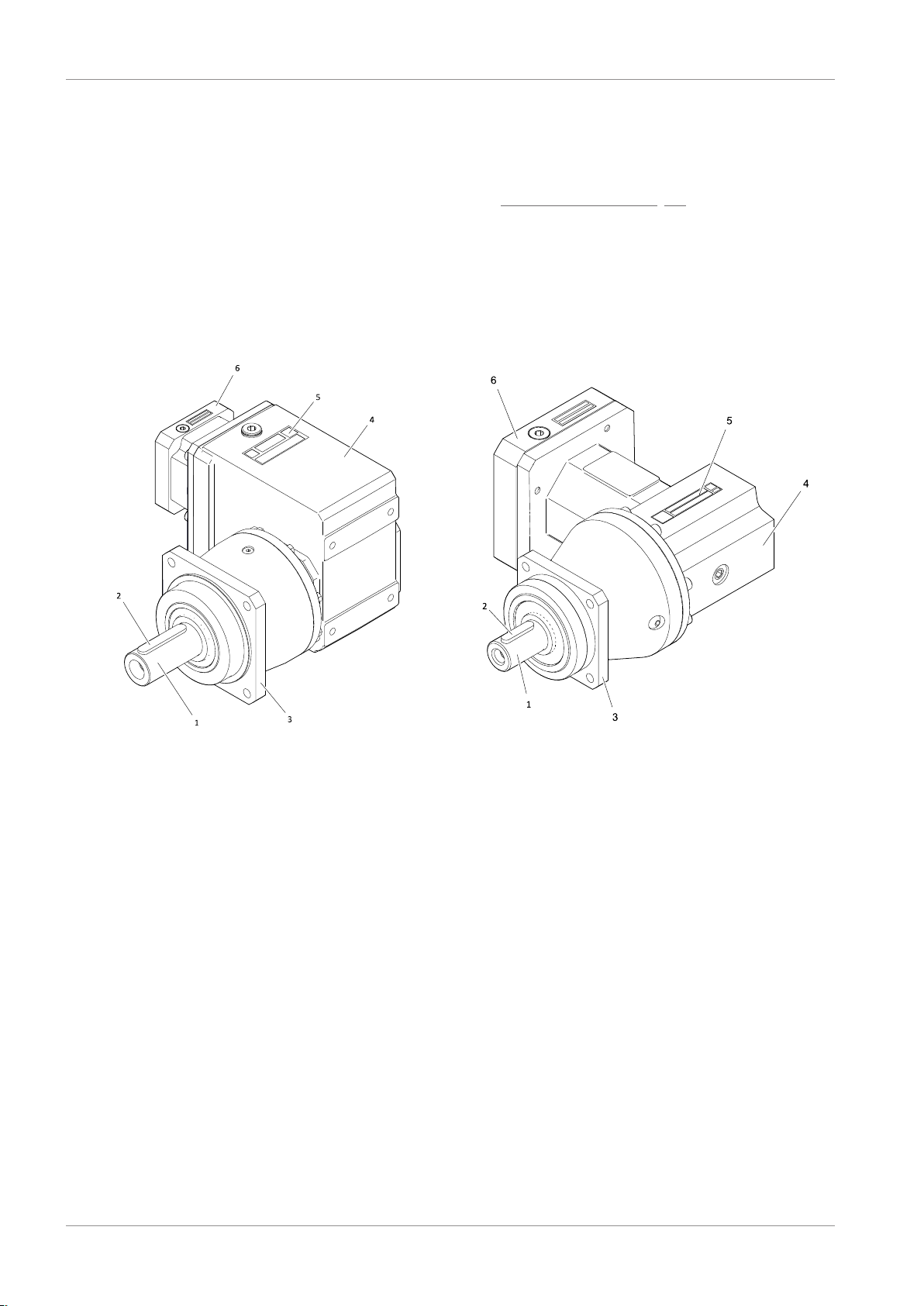
3.1.1 Basic structure of PK, PKX
Tab. 1: Basic structure of a P431_K202 gear unit (left) and P431_KX4 gear unit (right)
1 Solid shaft 2 Feather key (if present)
3 Output flange 4 Gear unit housing
5 Nameplate 6 ME motor adapter

3 | Product description
10/2019 | ID 443150_en.00
9
3.1.2 Basic structure of PHK, PHKX, PHQK
Tab. 2: Basic structure of a PHQ831_K402 gear unit (left) and PH731_KX7 gear unit (right)
1 Flange shaft 2 Output flange
3 Gear unit housing 4 Nameplate
5 ME motor adapter
3.1.3 Basic structure of KS
Tab. 3: Basic structure of a KS502F gear unit (left) and KS502S gear unit (right)
1a Flange hollow shaft 1b Hollow shaft with shrink ring
2 Output flange 3 Gear unit housing
4 Nameplate 5 ME motor adapter

3 | Product description
10
10/2019 | ID 443150_en.00
3.1.4 Basic structure of KL
Tab. 4: Basic structure of a KL102ANG gear unit (left) and KL102PF gear unit (right)
1a Hollow shaft 1b Solid shaft with feather key
2a Foot plates (option) 2b Output flange (option)
3 Nameplate 4 Gear unit housing
5 MQ motor adapter
3.2 Type designation
3.2.1 PK, PKX, PH5K – PH8K, PHKX, PHQ5K-PHQ8K type designation
In this chapter, you can find an explanation of the type designation for the gear unit types mentioned in the title.
Sample code
P 5 3 1 S G S S 0050 K102VF 0060 ME20
Explanation
Code Designation Design
P
PH
PHQ
Type Planetary gear unit with solid shaft
Planetary gear unit with flange shaft
Planetary gear unit with flange shaft
5Size 5 (example)
3Generation Generation 3
1Stages Single-stage
SHousing Standard
F
G
P
Shaft Flange shaft (PH, PHQ gear unit)
Solid shaft without feather key (P gear unit)
Solid shaft with feather key (P gear unit)

3 | Product description
10/2019 | ID 443150_en.00
11
Code Designation Design
S
D
Z
V
Bearing Standard bearing
Axially reinforced bearing (P gear unit)
Radially reinforced bearing (P gear unit)
Reinforced bearing (PH/PHQ gear unit)
S
R
Backlash Standard
Reduced
0050 Transmission ratio of output
(i x 10)
i = 5 (example)
K102VF
KX701VF
Input K1 right-angle gear unit (example)
KX7 right-angle gear unit (example)
0060 Transmission ratio of input
(i x 10)
i = 6 (example)
ME20
MF
MB
Motor adapter ME20 motor adapter (example) with EasyAdapt coupling
MF motor adapter with FlexiAdapt coupling
ServoStop motor adapter with brake
EZ
LM
Motor EZ synchronous servo motor
LM Lean motor
3.2.2 PH9K – PH10K, PHQ9K – PHQ12K type designation
In this chapter, you can find an explanation of the type designation for the gear unit types mentioned in the title.
Sample code
PH 9 3 1 F 0040 K513VF 0100 ME30
Explanation
Code Designation Design
PH
PHQ
Type Planetary gear unit with flange shaft
9Size 9 (example)
3Generation Generation 3
1Stages Single-stage
FShaft Flange shaft
0040 Transmission ratio (i x 10) i = 4 (example)
K513VF Input K5 right-angle gear unit (example)
0100 Transmission ratio of input
(i x 10)
i = 10 (example)
ME30
MF
MB
Motor adapter ME30 motor adapter (example) with EasyAdapt coupling
MF motor adapter with FlexiAdapt coupling
ServoStop motor adapter with brake
EZ
LM
Motor EZ synchronous servo motor
LM Lean motor

3 | Product description
12
10/2019 | ID 443150_en.00
3.2.3 KS type designation
In this chapter, you can find an explanation of the type designation for the gear unit types mentioned in the title.
Sample code
KS 5 0 2 G F 0200 ME
Explanation
Code Designation Design
KS Type Right-angle servo gear unit
5Size 5 (example)
0Generation Generation 0
2
3
Stages Two-stage
Three-stage
F
S
G
P
Shaft Flange hollow shaft
Hollow shaft with shrink ring
Solid shaft without feather key
Solid shaft with feather key
FHousing Standard
0200 Transmission ratio (i x 10) i = 20 (example)
ME
MEL
Motor adapter Motor adapter with EasyAdapt coupling
Motor adapter with EasyAdapt coupling for large motors
EZ
LM
Motor EZ synchronous servo motor
LM Lean motor
3.2.4 KL type designation
In this chapter, you can find an explanation of the type designation for the gear unit types mentioned in the title.
Sample code
KL 2 0 2 P G 0080 MQ
Explanation
Code Designation Design
KL Type Helical bevel gear unit
2Size 2 (example)
0Generation Generation 0
2Stages Two-stage
A
S
G
P
Shaft Hollow shaft with keyway
Hollow shaft with shrink ring
Solid shaft without feather key
Solid shaft with feather key
3 | Product description
10/2019 | ID 443150_en.00
13
Code Designation Design
G
F
NG
Housing Pitch circle diameter
Flange
Foot + pitch circle diameter
0080 Transmission ratio (i x 10) i = 8 (example)
MQ Motor adapter Square motor adapter with backlash-free plug-in coupling
EZ
LM
Motor EZ synchronous servo motor
LM Lean motor
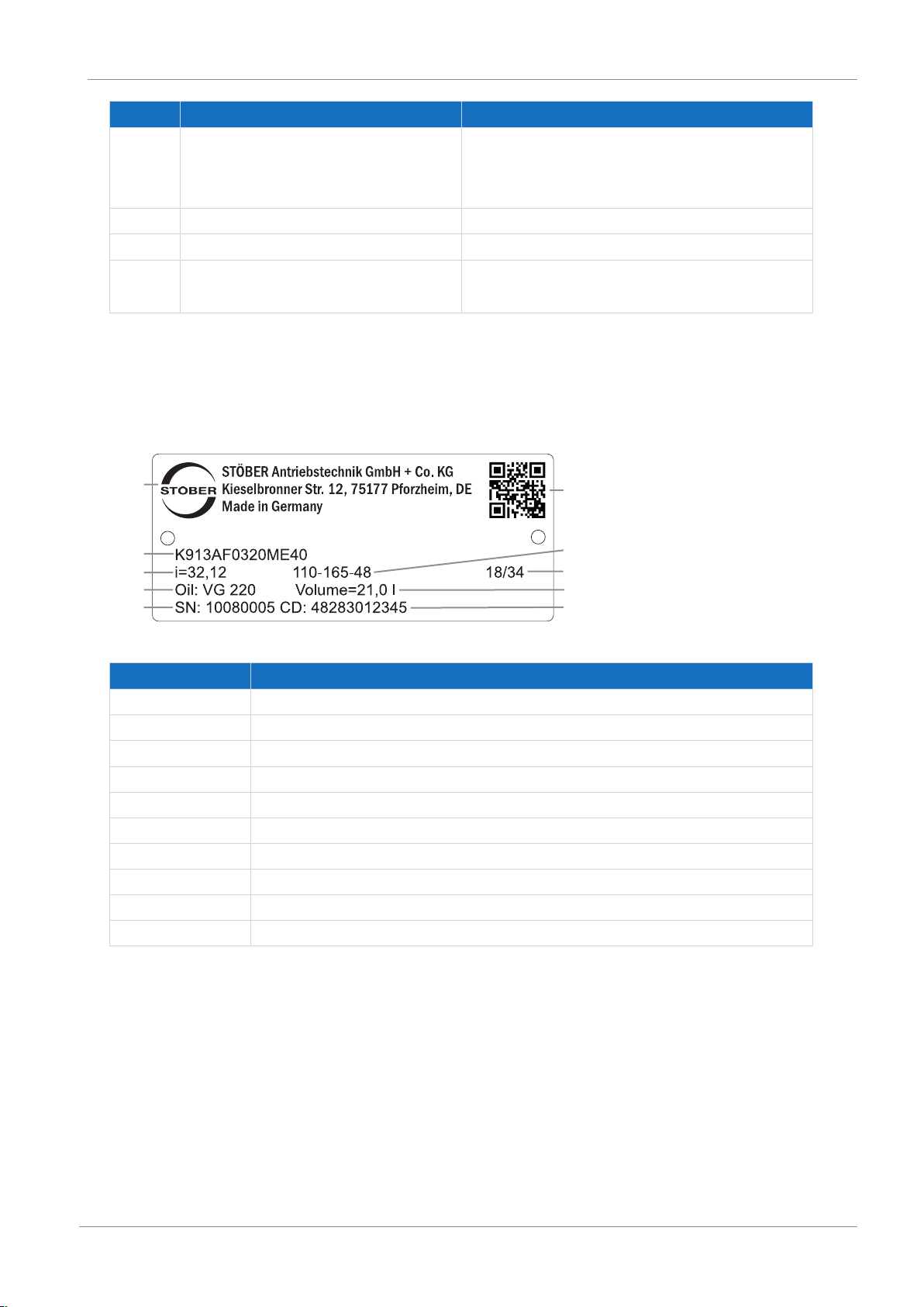
3.3 PK, PHK, KL nameplate
An example nameplate for the gear unit types listed above is explained in the figure below.
1
2
3
4
5
6
7
8
9
10
Code Designation
1 Name of manufacturer
2 Type designation
3 Gear ratio of the gear unit
4 Lubricant specification
5 Serial number of the gear unit
6 QR code (link to product information)
7 Dimensions of the motor adapter (pilot/bolt circle/motor shaft diameter)
8 Date of manufacture (year/calendar week)
9 Lubricant fill volume
10 Customer-specific data

3 | Product description
14
10/2019 | ID 443150_en.00
3.4 PKX, PHKX, KS nameplate
An example nameplate for the gear unit types listed above is explained in the figure below.
1
2
345678910
Code Designation
1 Name of manufacturer
2 Type designation
3 Gear ratio of the gear unit
4 Serial number of the gear unit
5 Dimensions of the motor adapter (diameter of pilot/bolt circle/motor shaft)
6 Customer-specific data
7 Lubricant specification
8 Lubricant fill volume
9 Date of manufacture (year/calendar week)
10 QR code (link to product information)
3.5 Mounting positions
3.5.1 PK, PHK, PHQK mounting positions
STOBER coordinates the lubricant fill volume and structure of the gear unit types listed above to the mounting position of
the gear unit in the machine. The mounting position of a gear unit is determined upon ordering and specified in the order
documents.
The standard mounting positions of the gear unit types listed above is depicted in the images below, using the PK gear unit
type with output on side 4 as an example. For PHK and PHQK gear unit types, the output shaft is designed as a flange shaft,
not a solid shaft.
The numbers identify the gear unit sides. The mounting position is defined by the gear side facing downwards.

3 | Product description
10/2019 | ID 443150_en.00
15
EL1 EL2 EL3
EL4 EL5 EL6
An adhesive label is applied to the gear unit that explains the designated mounting position. The arrow on the adhesive
label indicates the side with which the gear unit must be mounted facing down.
Fig.1: Adhesive label for the mounting position

3 | Product description
16
10/2019 | ID 443150_en.00
3.5.2 PKX, PHKX, KS mounting positions
STOBER coordinates the lubricant fill volume and structure of the gear unit types listed above to the mounting position of
the gear unit in the machine. The mounting position of a gear unit is determined upon ordering and specified in the order
documents.
The standard mounting positions of the gear unit types listed above are illustrated in the images below, using the PHKX
gear unit type as an example. For the PKX gear unit type, the output shaft is implemented as a solid shaft, not a flange
shaft. For the KS gear unit type, the output shaft is either implemented as a solid shaft, flange hollow shaft or hollow shaft
with shrink ring on side 3.
The numbers identify the gear unit sides. The mounting position is defined by the gear side facing downwards.
EL1 EL2 EL3
EL4 EL5 EL6
An adhesive label is applied to the gear unit that explains the designated mounting position. The arrow on the adhesive
label indicates the side with which the gear unit must be mounted facing down.
Fig.2: Adhesive label for the mounting position

3 | Product description
10/2019 | ID 443150_en.00
17
3.5.3 KL mounting positions
The KL gear unit can be installed in any mounting position. The figure below illustrates the gear sides referenced by the
shaft and housing designs.
3.6 Direction of rotation
The following figures illustrate the direction of rotation of the output in relation to the direction of rotation at the input of
the respective gear unit. All gear unit types are shown in mounting position EL1
Output on side 4 of K gear unit Output on side 3 of K gear unit
Tab. 5: Direction of rotation of the PK gear unit
PKX3 − PKX5 PKX7
Tab. 6: Direction of rotation of the PKX gear unit

3 | Product description
18
10/2019 | ID 443150_en.00
Output on side 4 of K gear unit Output on side 3 of K gear unit
Tab. 7: Direction of rotation of the PHK, PHQK gear unit
PH3KX − PH5KX PH7KX − PH8KX
Tab. 8: Direction of rotation of the PHKX gear unit
KS
Tab. 9: Direction of rotation of the KS gear unit

3 | Product description
10/2019 | ID 443150_en.00
19
Output on side 4 Output on side 3
Tab. 10: Direction of rotation of the KL gear unit
The specified direction of rotation also applies to other designs of the KL gear unit:
§Design with hollow shaft (A), for which the entry side of the machine shaft corresponds to the side of the solid shaft
that is shown
§Design with hollow shaft with shrink ring (S), for which the position of the shrink ring corresponds to the side of the
solid shaft that is shown.
3.7 Ambient conditions
Standard ambient conditions for transport, storage and operation of the gear unit are described in this chapter. Deviating
ambient conditions for special designs are specified in the order confirmation. Ambient conditions for motors attached to a
gear unit can be found in the technical documentation of the motor.
Feature Description
Transport/storage surrounding temperature −10 °C to +50 °C
Surrounding operating temperature 0 °C to +40 °C
Installation altitude ≤ 1000 m above sea level
Notes
In order to prevent corrosion damage and damage to the shaft seal rings, protect the drive from the following influences:
§Environments with harmful oils, acids, gases, vapors, dust or radiation
§Extreme temperature fluctuations with high humidity
§Thawing or icing
§Strong UV radiation (e.g. direct sunlight)
§Presence of salt spray
§Sparks
In potentially explosive atmospheres, only gear units in an explosion-proof design in accordance with (ATEX) Directive
2014/34/EU may be used. Separate documentation applies to the explosion-proof design.

3 | Product description
20
10/2019 | ID 443150_en.00
3.8 Other product features
Other features of gear units in the standard design can be found in the following table.
Feature Description
Maximum permitted gear unit temperature (on the surface
of the gear unit)
≤ 90°C
Paint Black RAL 9005
Lubricant Synthetic; for specification and quantity, see nameplate
Ventilation Gear unit housing closed on all sides, no ventilation
provided
Weight See order documents
Protection class IP65
With a geared motor, keep in mind that the motor protection class may be lower.
3.9 Additional documentation
You will find more information about the product at http://www.stoeber.de/en/downloads/. Enter the ID of the
documentation in the Search... field.
Product combination Catalog title ID
Gear unit + MB motor adapter with brake Motor adapters with brake 441904
Gear unit + ME/MEL/MF/MFL motor adapter Servo gear units 443054_en
Gear unit + MQ motor adapter Servo gear units 443054_en
Gear unit + EZ synchronous servo motor EZ synchronous servo geared motors 442437_en
Gear unit + LM Lean motor Lean motors 443016_en
If you have questions about your drive that are not answered by this documentation, please contact STOBER Service
(Service [}45]).
This manual suits for next models
22
Table of contents
Other Stober Engine manuals


Popular Engine manuals by other brands

Ametek
Ametek dunkermotoren BG dCore Series Translation of the original manual

Schachner Elektrofahrzeuge
Schachner Elektrofahrzeuge MM13 user manual

Vexta
Vexta CFK II Series operating manual

STG-BEIKIRCH
STG-BEIKIRCH EM Tandem RWA Technical information and operating instruction

phytron
phytron ZSH 57 Assembly instructions

Danfoss
Danfoss VLT OneGearDrive instruction manual


