BILT HARD 10-INCH User manual

10-INCH DRILL PRESS
IMPORTANT:
Your new tool has been engineered and manufactured to highest standards for dependability,
ease of operation, and operator safety. When properly cared for, this product will supply you years of rugged,
trouble-free performance. Pay close attention to the rules for safe operation, warnings, and cautions. If you use
your tool properly and for its intended purpose, you will enjoy years of safe, reliable service.
INSTRUCTION MANUAL
Thank you for ordering our product. If you have any issue, please email with

2
CONTENTS
3EMOCLEW
Introduction ..................................................................................................... 3
Specifications................................................................................................... 3
4YTEFAS
General Safety Rules........................................................................................ 4
Drill Press Safety Warnings ............................................................................. 6
Electrical Information....................................................................................... 8
BEFORE OPERATING 9
Unpacking & Packing List................................................................................ 9
Know Your Drill Press .................................................................................... 10
Assembly & Adjustment................................................................................. 11
OPERATION & MAINTENANCE 61
Operation ....................................................................................................... 16
Maintenance................................................................................................... 17
Troubleshooting Guide................................................................................... 19
Exploded View & Parts List............................................................................ 21

3
SPECIFICATIONS
Motor 120V, 60 Hz, 6.2A
Speeds 350-3,000 r/min. (RPM)
Swing 10"
Table Size 7-5/8 in. x 6-1/2 in.
Total Height 29"
INTRODUCTION
Thanks for purchasing the Drill Press. We know you are excited to put your tool to work, but first, please take
a moment toread through the manual. Safe operation of this tool requires that you read and understand this
operator’s manual and all the labels affixed to the tool. This manual provides information regarding potential safety
concerns, as well as helpful assembly and operating instructions for your tool.
NOTE: The following safety information is not meant to cover all possible conditions and situations that may occur.
reserves the right to change this product and specifications at any time without prior notice.
Keep this manual available to all users during the entire life of the tool and review it frequently to maximize
safety for both yourself and others.
SAFETY ALERT SYMBOL: Indicates danger, warning, or caution. The safety symbols and the explanations
with them deserve your careful attention and understanding. Always follow the safety precautions to reduce the
risk of fire, electric shock or personal injury. However, please note that these instructions and warnings are not
substitutes for proper accident prevention measures.

4
GENERAL SAFETY RULES
WORK AREA SAFETY
1. Keep work area clean and well lit. Cluttered or dark
areas invite accidents.
2. Do not operate power tools in explosive atmo-
spheres, such as in the presence of flammable liquids,
gases or dust. Power tools create sparks which may ig-
nite the dust or fumes.
3. Keep children and bystanders away while operating
a power tool. Distractions can cause you to lose control.
ELECTRICAL SAFETY
1. Power tool plugs must match the outlet. Never mod-
ify the plug in any way. Do not use any adapter plugs
with earthed (grounded) power tools. Unmodified plugs
and matching outlets will reduce risk of electric shock.
2. Avoid body contact with earthed or grounded surfac-
es such as pipes, radiators, ranges and refrigerators.
There is an increased risk of electric shock if your body
is earthed or grounded.
3. Do not expose power tools to rain or wet conditions.
Water entering a power tool will increase the risk of elec-
tric shock.
4. Do not abuse the cord. Never use the cord for car-
rying, pulling or unplugging the power tool. Keep cord
away from heat, oil, sharp edges or moving parts.
Damaged or entangled cords increase the risk of electric
shock.
5. When operating a power tool outdoors, use an ex-
tension cord suitable for outdoor use. Use of a cord
suitable for outdoor use reduces the risk of electric
shock.
6. If operating a power tool in a damp location is un-
avoidable, use a ground fault circuit interrupter (GFCI)
protected supply. Use of a GFCI reduces the risk of elec-
tric shock.
PERSONAL SAFETY
1. Stay alert, watch what you are doing and use com-
mon sense when operating a power tool. Do not use a
power tool while you are tired or under the influence
of drugs, alcohol or medication. A moment of inatten-
tion while operating power tools may result in serious
personal injury.
2. Use personal protective equipment. Always wear
eye protection. Protective equipment such as a respira-
tory mask, non-skid safety shoes and hearing protection
used for appropriate conditions will reduce the risk of
personal injury.
3. Prevent unintentional starting. Ensure the switch is
in the off-position before connecting to power source
and/or battery pack, picking up or carrying the tool.
Carrying power tools with your finger on the switch or
energizing power tools that have the switch on invites
accidents.
4. Remove any adjusting key or wrench before turning
the power tool on. A wrench or a key left attached to a
rotating part of the power tool may result in personal
injury.
5. Do not overreach. Keep proper footing and balance
at all times. This enables better control of the power
tool in unexpected situations.
6. Dress properly. Do not wear loose clothing or jew-
elry. Keep your hair and clothing away from moving
parts. Loose clothes, jewelry or long hair can be caught
in moving parts.
Safety is a combination of common sense, staying alert and knowing how your item works. The term “power tool”
in the warnings refers to your mains-operated (corded) power tool or battery-operated (cordless) power tool.
SAVE THESE SAFETY INSTRUCTIONS.
WARNING! Read all safety warnings and all instructions. Failure to follow the warnings and instructions may
result in electric shock, fire and/or serious injury.

5
GENERAL SAFETY RULES
7. If devices are provided for the connection of dust
extraction and collection facilities, ensure these are
connected and properly used. Use of dust collection
can reduce dust-related hazards.
POWER TOOL USE AND CARE
1. Do not force the power tool. Use the correct power
tool for your application. The correct power tool will
do the job better and safer at the rate for which it was
designed.
2. Do not use the power tool if the switch does not turn
it on and off. Any power tool that cannot be controlled
with the switch is dangerous and must be repaired.
3. Disconnect the plug from the power source and/or
the battery pack from the power tool before making
any adjustments, changing accessories, or storing
power tools. Such preventive safety measures reduce
the risk of starting the power tool accidentally.
4. Store idle power tools out of the reach of children
and do not allow persons unfamiliar with the power
tool or these instructions to operate the power tool.
Power tools are dangerous in the hands of untrained us-
ers.
5. Maintain power tools. Check for misalignment or
binding of moving parts, breakage of parts and any
other condition that may affect the power tool’s opera-
tion. If damaged, have the power tool repaired before
use. Many accidents are caused by poorly maintained
power tools.
6. Keep cutting tools sharp and clean. Properly main-
tained cutting tools with sharp cutting edges are less
likely to bind and are easier to control.
7. Use the power tool, accessories and tool bits, etc.
in accordance with these instructions, taking into ac-
count the working conditions and the work to be per-
formed. Use of the power tool for operations different
from those intended could result in a hazardous situa-
tion.
8. Use clamps to secure your workpiece to a stable
surface. Holding a workpiece by hand or using your
body to support it may lead to loss of control.
9. KEEP GUARDS IN PLACE and in working order.
SERVICE
1. Have your power tool serviced by a qualified repair
person using only identical replacement parts. This
will ensure that the safety of the power tool is main-
tained.
CALIFORNIA PROPOSITION 65 WARNING
Some dust created by power sanding, sawing, grinding,
drilling, and other construction activities may contain
chemicals, including lead, known to the State of Califor-
nia to cause cancer, birth defects, or other reproductive
harm. Wash hands after handling. Some examples of
these chemicals are:
• Lead from lead-based paints.
• Crystalline silica from bricks, cement, and other
masonry products.
• Arsenic and chromium from chemically treated
lumber.
Your risk from these exposures varies depending on
how often you do this type of work. To reduce your ex-
posure to these chemicals, work in a well-ventilated area
with approved safety equipment such as dust masks
specially designed to filter out microscopic particles.
Safety is a combination of common sense, staying alert and knowing how your item works. The term “power tool”
in the warnings refers to your mains-operated (corded) power tool or battery-operated (cordless) power tool.
SAVE THESE SAFETY INSTRUCTIONS.
WARNING! Read all safety warnings and all instructions. Failure to follow the warnings and instructions may
result in electric shock, fire and/or serious injury.

6
DRILL PRESS SAFETY WARNINGS
1. TOOL PURPOSE. This drill press is designed to
drill through metal and wood. Drilling through other
materials could result in fire, injury, or damage to the
workpiece. Using the machine for any other purpose
for which it is not designed may result in serious in-
juries, machine damage and voiding of the warranty.
2. MACHINE MOUNTING. For operation safety, the
drill press must be securely mounted onto a flat and
stable surface or stand.
3. PERSONAL SAFETY.
• Always wear ANSI Z87.1-approved glasses with
side shields, hearing protection, and a dust mask.
• Do not wear loose clothing or jewelry, as they
might get drawn in by the tool. Tie back long hair.
• Do not wear gloves while operating this machine.
4. ELECTRIC CORDS. Keep cords away from heat,
oil, sharp edges, and moving parts of the tool. Have
an electrician replace or repair damaged or worn
cords immediately.
5. TOOL & ACCESSORIES INSPECTION. Before op-
eration, check the tool and accessories for any dam-
age or missing parts. Do not use the tool if any part
is missing or damaged. Make sure all adjustments
are correct and all connections are tight. Keep all
guards in place.
6. DRILLING ACCESSORIES.
• Make sure the drill bit is not damaged before
use, only use undamaged drill bits
• Make sure the drill bit is securely locked in the
chuck before turning ON.
• Make sure the chuck key is removed from the
chuck before turning ON.
• Use clamps or a vise to secure a workpiece to
the table. This will prevent the workpiece from
rotating with the drill bit.
7. Make sure the table lock is tightened before start-
ing the drill press.
8. WORKPIECE REQUIREMENTS.
• Only stand workpieces sturdy enough to with
stand the force of the drill bit.
• Inspect workpiece for imperfections, nails,
staples, etc. before drilling. Never drill stock that
has questionable imperfections or embedded
foreign objects.
• Do not drill materials without a flat surface un
less a suitable support is used (clamp or vise).
9. PREVENTING ACCIDENTAL STARTING. Make sure
the power switch is in the OFF position prior to plug-
ging in the machine. Always make sure the power
switch is in the OFF position and the machine is un-
plugged when doing any cleaning, assembly, setup
operations, or when not in use.
10. Do not operate this tool until it is completely as-
sembled and installed according to the instructions.
11. Remove scrap pieces and other objects from the
table before turning ON the drill press.
12. DRILLING THE WORKPIECE.
• Allow spindle to reach full speed before drilling
the workpiece.
• Never start the machine with the drill bit pressed
against the workpiece.
• Adjust the table or depth stop to avoid drilling
into the table.
• Set the drill press to the speed that is appropriate
for the material being drilled.
13. Do not touch moving pieces. Keep hands away
from the drill bit during operation. If cleaning is nec-
essary, turn off the machine and use a brush to re-
move sawdust and chips instead of your hands.
14. Never perform layout, assembly or set-up work
on the table while the machine is ON.
WARNING! Do not operate the power tool until you have read and understood the following instructions and
the warning labels.

7
DRILL PRESS SAFETY WARNINGS
15. After turning off the drill press, wait until the
spindle comes to a complete stop before touching
the workpiece. Always turn the drill OFF before re-
moving scrap from the table.
16. Before leaving the machine, always turn OFF and
unplug the machine, remove the drill bit, and clean
the table. Turn Off and unplug the machine before
cleaning, making adjustments or changing drill bits.
Accidental start-ups may occur if the tool is plugged
in during an accessory change or adjustment.
17. CLEANING. Never use solvents to clean plastic
parts. Solvents could dissolve or otherwise dam-
age the material. Use only a soft damp cloth to clean
plastic parts.
18. REPLACEMENTS. Should any component of
your drill press be missing/damaged or fail in any
way, shut OFF the switch and remove the plug
from power supply outlet. Replace the missing,
damaged, or failed parts using only identical re-
placement parts before resuming operation.
CALIFORNIA PROPOSITION 65 WARNING
Some dust created by power sanding, sawing, grind-
ing, drilling, and other construction activities may
contain chemicals, including lead, known to the
State of California to cause cancer, birth defects, or
other reproductive harm. Wash hands after handling.
Some examples of these chemicals are:
• Lead from lead-based paints.
• Crystalline silica from bricks, cement, and other
masonry products.
• Arsenic and chromium from chemically treated
lumber.
Your risk from these exposures varies depending
on how often you do this type of work. To reduce
your exposure to these chemicals, work in a well-
ventilated area with approved safety equipment such
as dust masks specially designed to filter out micro-
scopic particles.
WARNING! Do not operate the power tool until you have read and understood the following instructions and
the warning labels.

8
ELECTRICAL INFORMATION
AMPERAGE REQUIRED GAUGE FOR EXTENSION CORDS
25 ft. 50 ft. 100 ft. 150 ft.
2.3A 18 gauge 16 gauge 16 gauge 14 gauge
3. Check
with a licensed electrician or service personnel if you do not completely
understand the grounding instructions or whether the tool is properly grounded.
4. Use only three-wire extension cords
that have three-pronged plugs and outlets
that accept the tool’s plug (INSERT CR). Repair or replace a damaged or worn cord
immediately.
CAUTION!
In all cases, make certain the outlet in question is properly grounded. If
you are not sure, have a licensed electrician check the outlet.
GUIDELINES AND RECOMMENDATIONS FOR EXTENSION CORDS
GROUNDING INSTRUCTIONS
In the event of a malfunction or breakdown
, grounding provides the path of least resistance for an electric
current and reduces the risk of electric shock. This tool is equipped with an electric cord that has an
equipment grounding conductor and a grounding plug. The plug MUST be plugged into a matching outlet
that is properly installed and grounded in accordance with ALL local codes and ordinances.
1. Do not modify the plug provided.
If it will not fit the outlet, have the proper outlet installed by a licensed
electrician.
2. Improper connection
of the equipment grounding conductor can result in electric shock. The conductor
with the green insulation (with or without yellow stripes) is the equipment grounding conductor. If repair or
replacement of the electric cord or plug is necessary, DO NOT connect the equipment grounding conductor
to a live terminal.
1. Examine extension cord before use. Make sure your extension cord is properly wired and in good condition.
Always replace a damaged extension cord or have it repaired by a qualified person before using it.
2. Do not abuse extension cord. Do not pull on cord to disconnect from receptacle; always disconnect by pulling on
plug. Disconnect the extension cord from the receptacle before disconnecting the product from the extension cord.
Protect your extension cords from sharp objects, excessive heat and damp/wet areas.
3. Use a separate electrical circuit for your tool. This circuit must not be less than a 12-gauge wire and should be
protected with a 15A time-delayed fuse. Before connecting the motor to the power line, make sure the switch is in
the OFF position and the electric current is rated the same as the current stamped on the motor nameplate. Running
at a lower voltage will damage the motor.
Fig. 1
When using an extension cord, be sure to use one heavy enough to carry the current your product will draw. An un-
dersized cord will cause a drop in line voltage resulting in loss of power and overheating. The table below shows the
correct size to be used according to cord length and ampere rating. When in doubt, use a heavier cord. The smaller
the gauge number, the heavier the cord.

9
UNPACKING & PACKING LIST
UNPACKING
With the help of a friend or trustworthy foe, carefully remove the Drill Press from the packaging. Make sure to take
out all contents and accessories. Do not discard the packaging until everything is removed. Check the packing list
below to make sure you have all of the parts and accessories.
PACKING LIST
ASSEMBLY / ADJUSTMENT TOOLS
The tools listed below are not included but are required for either assembly or adjustment:
• Adjustable wrench
• Hammer and block of wood or rubber mallet, or dead-blow hammer
WARNING! Do not plug in or turn on the tool until it is fully assembled according to the instructions. Failure
to follow the safety instructions may result in serious personal injury.
1
2
5
6
3
4
7
89
12
13
14
10
Head / Motor Assembly....................................1
Table Locking Handle.......................................1
Table Asssembly...............................................1
Base.............................................................1
Column Assembly............................................1
Chuck...............................................................1
Chuck Key........................................................1
Feed Handles...................................................3
Hex Wrench.....................................................2
Hex bolt M 8×20...............................................3
1.
2.
3.
4.
5.
6.
7.
8.
9.
10.
Depth gauge.....................................................1
11.
Column collar...................................................1
12.
Table adjustment handle...................................1
13.
Worm gear........................................................1
14.
11
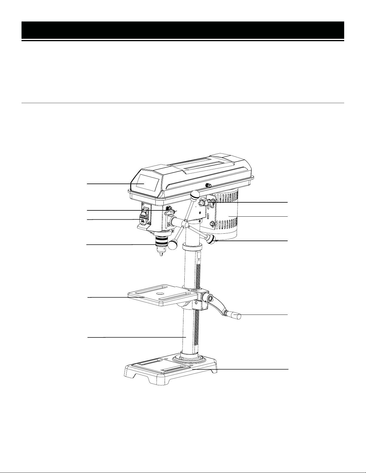
KNOW YOUR DRILL PRESS
TOOL PURPOSE
Drill clean, precise cylindrical holes into workpieces or enlarge existing holes with your Drill Press. Refer to the fol-
lowing diagrams to become familiarized with all the parts and controls of your Drill Press. The components will be
referred to later in the manual for assembly and operation instructions.
10
DRILL PRESS
Housing Cover
Chuck Key
Chuck
Motor
Feed Handle
Belt Tension
Base
Table assembly
Table Lock
ON/OFF Switch
Column

11
Table assembly
Worm gear
D-shaft
Table lock handle
Threaded hole
Slot
ASSEMBLY & ADJUSTMENTS
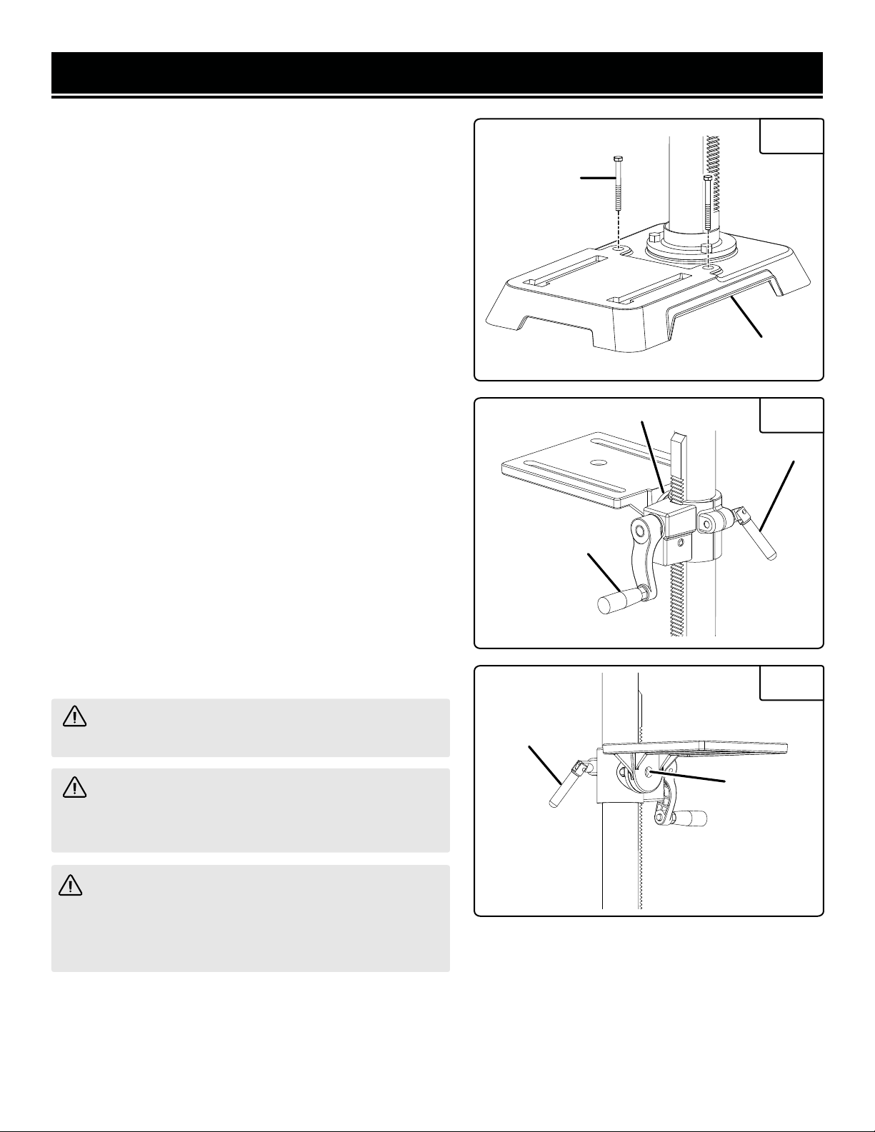
ATTACHING COLUMN ASSEMBLY TO BASE
1. Place the column tube on the base,aligning the column
support holes to the base holes.
2. Install a hex head bolt in each of the three column
support holes and tighten using the adjustable wrench
(not included).
INSTALLING TABLE ASSEMBLY
WARNING! Do not plug in or turn on the tool until it
is fully assembled according to the instructions. Failure
to follow the safety instructions may result in serious
personal injury.
Fig. 3
Fig. 4
Gear rack
Base
Hex bolt
Column Fig. 2
(Fig. 2)
(Fig. 3-6)
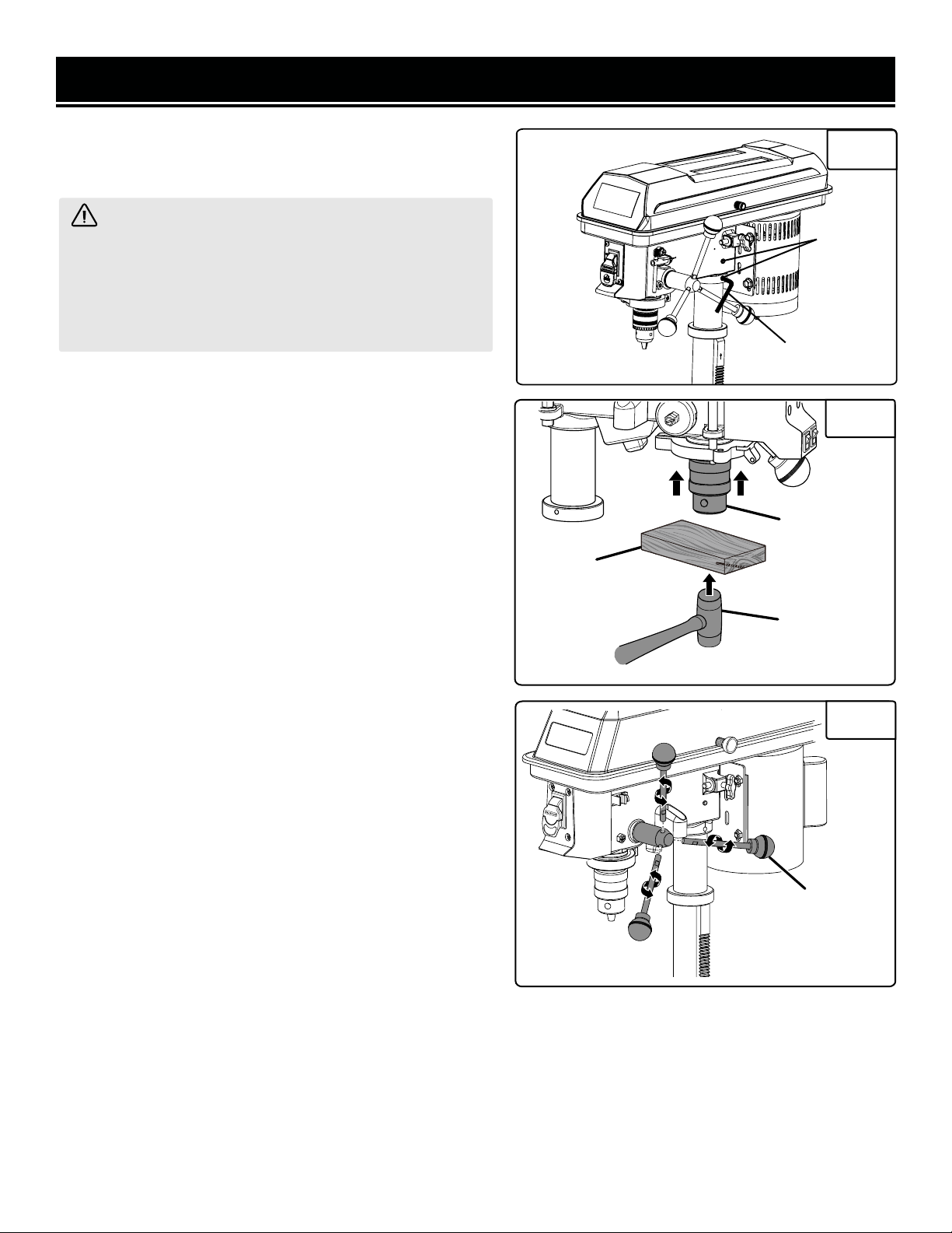
1. Loosen the set screw in the column collar. Remove the
column collar and gear rack from the column and set aside.
2. Clean the spindle with a degreaser before installing the
chuck into the head.
3. Locate the worm gear and feed the D-shaft through the
hole in the table assembly.
4. Install table adjustment handle over the end of the D-
shaft so that the flat side of the shaft aligns with the set
screw.Tighten the set screw using the hex key.
5. Feed the gear rack through the slot in the table assembly
so that the teeth are facing out and the longer smooth end
faces up. The worm gear should engage the gear rack.
6. Using both hands, slide the entire table assembly and
gear rack onto the column until the bottom of the gear rack
is positioned in the base collar and against the column.
7. Slide the column collar, bevel-side down, over the
column until the beveledside engages the beveled end ofthe
gear rack. Tighten the set screw in the collar using the hex
key. Do not overtighten.
Table assembly
Fig. 5
Gear rack
Column collar
Set screw
Base collar
NOTE: You should be able to move the table from side to
side.
Locate the table lock handle. Insert it into the threaded
hole at the rear of the table assembly and tighten by hand.
If the drill press is to be usedin a permanent location, secure
it to a workbench or other stable surface.
If the drill press is to be used as a portable tool, fasten it
permanently to a mounting board that can easily be clamped
to a workbench or other stable surface. The mounting board
should be of sufficient size to avoid tipping while drill press
is in use. Any good grade plywood or chipboard with a
3/4 in. thickness is recommended.
1. Mark holes on surface where drill press is to be mounted
using holes in drill press base as a template for hole
pattern.
1. Place the head assembly upside down on a level, flat
surface.
2. Position chuck on spindle. Chuck should be fully opened
to avoid damaging jaws.
3. Using a piece of scrap wood to protect the chuck, firmly
tap the chuck into place using a mallet or hammer.
4. Position the head assembly onto the column with the
chuck positioned over the table.
NOTE: This head assembly is heavy. Get help when needed.
5. Slide the head assembly down as far as it will go. Align
the table assembly with the base and then tighten the
two head set screws with the hex key.
6. Attach the three feed handles by screwing them into the
threaded holes in the hub.
12
ASSEMBLY & ADJUSTMENTS
(Fig. 7-8)
(Fig. 9)
Chuck
Scrap wood
Fig. 8
WARNING! Before any assembly of the chuck to the
drill press spindle, clean all mating surfaces with a non-
petroleum based product; such as acetone or lacquer
thinner. Any oil or grease used in the packing of these
parts must be removed; otherwise the chuck may come
loose during operation.
INSTALLING CHUCK, HEAD ASSEMBLY, AND
FEED HANDLES
MOUNTING THE DRILL PRESS
Fig. 7
Feed handle
Mallet
Fig. 6
Set screw
Hex key
2. Drill holes through mounting surface.
3. Place drill press on mountingsurface,aligning holes in
the base with holes drilledinthe mounting surface.
4. Insert bolts (not included) and tighten securely with lock
washers andhex nuts (not included).
5. If lag bolts are used, make sure they are long enough to
go through holes in drill press base and material thedrill
press is beingmounted to. If machine bolts are used, make
sure bolts are longenough to gothrough holes in drill press,
the material being mounted to, and the lock washers and hex
nuts.
NOTE: All bolts should be inserted from the top. Install the
lock washers and hex nuts from the underside of the
workbench.
Once the drill press is securely mounted on a sturdy surface:
1. Check for vibrationwhen the motor is switched ON.
2. Adjust and retighten the mounting hardware as necessary.
3. Check the table assembly toassure smooth movement
up anddownthe column.
4. Check toassure that the spindle shaft moves smoothly.
13
ASSEMBLY & ADJUSTMENTS
Fig. 9
Fig. 10
Fig. 11
(Fig. 10)
ADJUSTING TABLE HEIGHT
WARNING! Use of controls or adjustments or per-
formance of procedures other than those specified herein
could result in hazardous radiation exposure.
WARNING! Before performing any adjustment, make
sure the tool is unplugged from the power supply and the
switch is in the OFF ( O ) position. Failure to heed this
warning could result in serious personal injury.
WARNING! Laser radiation. Avoid direct eye contact
with light source.
Mounting bolts
Base
Bevel scale
Table lock handle
Table lock handle
Hex bolt
Table adjustment handle
1. Holdthe table with one hand and loosen the table lock handle.
2. Rotate the table adjustment handle clockwise to raise the table.

Fig. 12
Fig. 13
Fig. 15
(Fig. 11-12)
ADJUSTING TABLE BEVEL
(Fig. 12)
ADJUSTING DEPTH GAUGE
(Fig. 13-15)
CHANGING SPEEDS
Drive belt
Motor pulley
Pivot nut
Pivot bolt
Tension bolt
Motor
Depth stop
locking collar
Depth gauge
14
ASSEMBLY & ADJUSTMENTS
3. Rotate the table adjustment handle counterclockwise to
lower the table.
4. Position the table to the desired height and retighten the
table lock handle.
The drill press is equipped with a tilting table that allows
you to drill angled holes. The table can be tilted left or right,
from 0º to 45º.
To tilt the table:
1. Loosen the large hex bolt located underneath the table.
2. Use the bevel scale to tilt the table to the desired angle.
3. Retighten the hex bolt securely.
Adjust the depth gauge when you need to drill a number of
holes to exactly the same depth.
1. Loosen the depth stop locking collar.
2. Rotate depth gauge to desired setting.
3. Retighten depth stop locking collar, if needed.
The spindle speed is determined by the location of the belt
on the pulleys inside the head assembly. The speed chart
located on the cover inside the head assembly shows the
recommended speed and pulley configuration for each
drilling operation.
NOTE: The pivot bolts located on the side of the tool should
allow the motor to move freely once the tension bolt is
loosened.If themotor is difficult to move, it may benecessary
to loosen the pivot bolts slightly (1/4turn). Do not retighten.
1. Lift head assembly cover from side to open.
2. Loosen the tension bolt until there is enough slack in the
belt for it to be repositioned around the pulleys.
3. Reposition the belt according to the speed chart.
Fig. 14
Spindle pulley
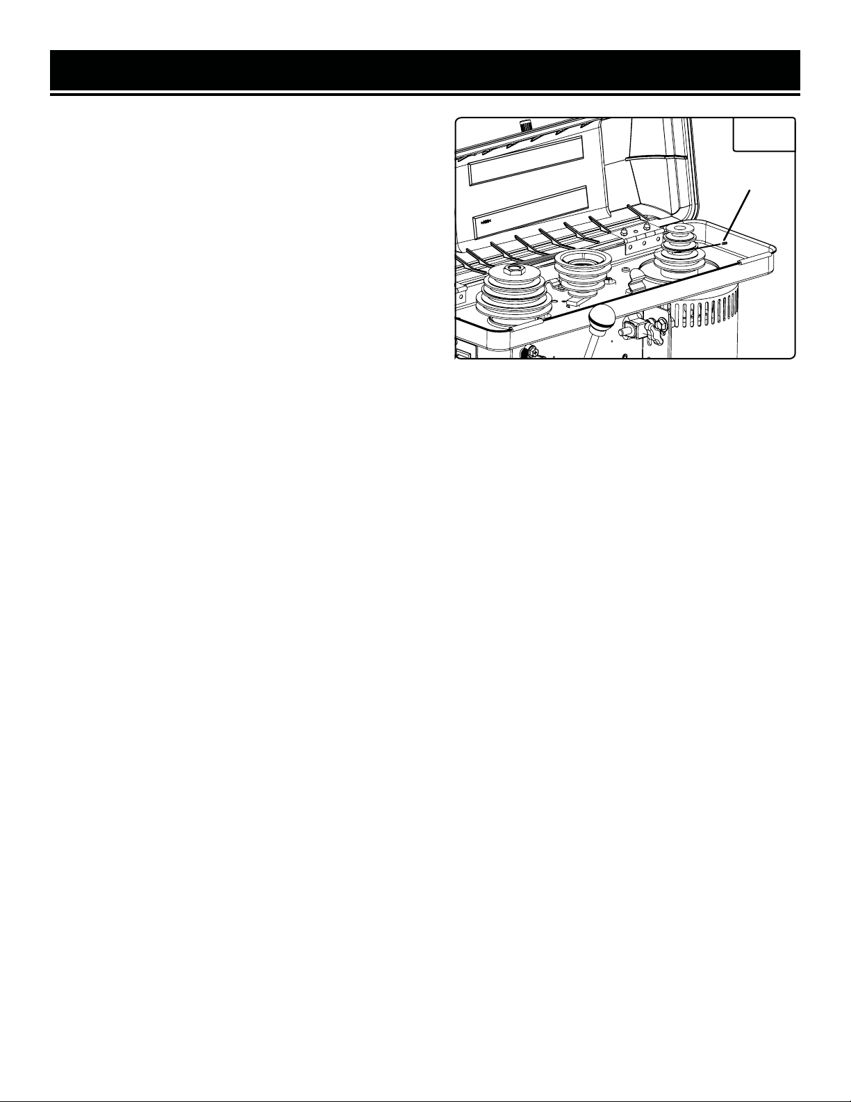
(Fig. 16)
PULLEYS
15
ASSEMBLY & ADJUSTMENTS
(1)When decreasing speed, move the belt downthe motor
pulley first and then down the spindle pulley.
(2)When increasing speed, move the belt up the spindle
pulley first and then up the motor pulley.
4. Turn the belt by hand until you are certain it is properly
aligned on the grooves of the pulleys.
5. Move the motor away from the tool until there is tension
in the belt.
6. Hold the motor in place and retighten the tension bolt.
Should you feel an unusually high level of vibration, the
pulleys may not be tightly secured on the motor and/or
spindle shafts. To make surethe pulleys are properly seated
and tight, locate the set screw on each of the pulleys.
Tighten each set screw with the hex key.
Fig. 16
Pulley set
screws

OPERATION
WARNING! Do not allow familiarity with tools to
make you careless.Remember that a careless fraction
of a second is sufficient to inflict serious injury.
WARNING! Always wear eye protection with side
shields marked to comply with ANSI Z87.1. Failure to
do so could result in objects being thrown into your
eyes, resulting in possible serious injury.
WARNING! Do not use any attachments or
accessories not recommended by the manufacturer of
this tool. The use of attachments or accessories not
recommended can result in serious personal injury.
WARNING! ALWAYS remove the switch key
when the tool is not in use and keep it in a safe place.
In the event of a power failure, turn the switch OFF
(O)and remove the key.This action will prevent the
tool from accidentally starting when power returns.
WARNING! Always make sure the workpiece is
not in contact with the bit before operating the switch
to start the tool. Failure to heed this warning may
cause the workpiece to be kicked back toward the
operator and result in serious personal injury.
WARNING! To prevent the workpiece or the backup
material from being torn from your hand while drilling,
position them against the left side of the column. If the
workpiece or the backup material are not long enough
to reach the column, clamp them to the table. Failure to
do this could result in personal injury.
The drill press is equipped with a power switch that has a
built-in locking feature. This feature is intended to prevent
unauthorized and possible hazardous use by children and
others.
To turn the drill press on:
With the switch key inserted into the switch, lift the switch
to turn ON ( l ).
To turn the drill press off:
With the switch key inserted into the switch, push the
switch down to turn OFF ( O ).
To LOCK the drill press:
1. Place the switch in the OFF ( O ) position.
2. Remove the switch key from the switch and store in a
secure location.
Fig. 17
(Fig. 17)
POWER SWITCH
Power off
Switch key
Power on
APPLICATIONS
You may use this tool for the purposes listed below:
1. Drilling in wood.
2. Drilling in ceramics, plastics, fiberglass, and laminates.
3. Drilling in metals.
16

OPERATION
WARNING! Use only the self-ejecting chuck key
provided. Always remove chuck key. Failure to heed this
warning could result in serious personal injury.
WARNING! Donot insert drill bitinto chuck jaws and
tighten as shown in figure 20. This could cause drill bit to
be thrown from the drill press, resulting in possible
serious personal injury or damage to the chuck.
Fig. 18
Fig. 19
The self-ejecting chuck key ensures the chuck key is removed
from the chuck before the drill press is turned on.
In order to loosen or tighten the chuck using the chuck key,
push the key into the key hole located on the chuck. Rotate
the key clockwise to tighten the chuck or counterclockwise
to loosen the chuck.
(Fig. 18)
SELF-EJECTING CHUCK KEY
The table can be rotated out of the way when drilling large
objects.
1. Loosenthe table lock handle.
2. Rotate the table to the desired position.
3. Retighten the table lock handle.
(Fig. 19)
TABLE ROTATION
1. Unplug the drill press.
2. Open or close the chuck jaws to a pointwhere the opening
is slightly larger than the bit size youintend to use.
3. Insert drill bit into the chuck the full length of the jaws.
1. Using a clamping device, secure the workpiece to the work-
table. To protect the top surface of the workpiece,use a piece
of scrap wood between the clamping device and the workpiece.
(Fig. 20)
INSTALLING AND REMOVING BITS
(Fig. 21)
DRILLING
Chuck key
Table assembly
Table lock handle
Key hole
4. Unplug the drill press.
5. Open or close the chuck jaws to a point where the opening
is slightly larger than thebit size you intend to use.
6. Insert drill bit intothe chuck the full length ofthe jaws.
Fig. 20
17

OPERATION
Fig. 21
2. Select theproper drill bit based on the hole size desired.
For large holes, drill a pilot hole first, using a smaller diameter
bit.
3. Select and set the recommended spindle speed. Refer to
“Changing Speeds” in the Adjustments section of this manual.
4. Set table assembly to desired height. Refer to “Adjusting
Table” Height in theAdjustments section.
5. If desired,set feed shaft at desired spindle depth. Refer to
“Adjusting Depth Gauge” in the Adjustments section.
6. Make surethe work table is free of all loose objects and
the bit is not in contact with the workpiece.
7. Plug electrical cord into powersupply and turn switch ON.
Make sure spindle rotates freely.
8. Slowly lower drill bit into workpiece. Do not force the bit;
let the drill press do the work.
9. Once the hole is completed,allow the spindle to return to
its normal position. This will automatically raise the chuck
and bit.
If a large hole is needed,it’s a good idea to drill a smaller pilot
hole before drilling the final one. Your hole will be more
accurately positioned, rounder, and the bits will last longer.
If the hole is deeper than it is wide, back offoccasionally to
clear the chips.
When drilling metal, lubricate the bit with oil to improve drilling
action and increase bit life.
As you increase the drill size, you may need to reduce the
spindle speed.
If drilling a throughhole, make sure that the bit will not drill into
the table after moving through the workpiece.
DRILLING TIPS
Clamp
Scrap wood
Workpiece
18

OPERATION
DRILLING SPEEDS
There are a few important factors to keep in mind when determining the best drilling speed:
• Material type
• Hole size
• Drill bit or cutter type
• Quality desired
Smaller drill bits require greater speed than larger drill bits. Softer materials require greater speed than harder ma-
terials.
DRILLING WOOD
• Brad point bits are preferred. Metal-piercing twist bits may be used on wood.
• Do not use auger bits. Auger bits turn so rapidly that they can lift the workpiece off of the table and whirl it around.
• To prevent splintering, feed drill bit slowly right as the bit is about to cut through to the backside of the workpiece.
• To reduce splintering and protect the point of the bit, use scrap wood or a base block under the workpiece.
• Always protect the drill bit by positioning the table so that the drill bit will enter the center hole when drilling
through the workpiece.
FEEDING THE DRILL BIT
• Pull down on the feed handles with only enough force to allow the drill bit to cut.
• Feeding too rapidly might stall the motor, cause the belt to slip, damage the workpiece, or break the drill bit.
• Feeding too slowly will cause the drill bit to heat up and burn the workpiece.
MAINTENANCE
ROUTINE INSPECTION
Before each use, inspect the tool. If any of these following conditions exist, do not use until parts are replaced.
Check for:
• Loose hardware or improper mounting
• Misalignment
• Damaged cord / electrical wiring
• Cracked or broken parts
• Any other condition that may affect its safe operation
WARNING! To avoid accidents, turn OFF and unplug the tool from the electrical outlet before cleaning,
adjusting, or performing any maintenance or lubrication work.
WARNING! Any attempt to repair or replace electrical parts on this tool may be hazardous. Servicing of the
tool must be performed by a qualified technician. When servicing, use only identical replacement parts. Use of
other parts may be hazardous or induce product failure.
CAUTION! Most plastics are susceptible to damage from various types of commercial solvents. Do not use
any cleaning products that could damage plastic parts. Some of these include but are not limited to: gasoline,
carbon tetrachloride, chlorinated cleaning solvents, and household detergents that contain ammonia.
19

MAINTENANCE
CLEANING & STORAGE
1. After every operation, use a vacuum to remove sawdust or metal shavings from the tool surfaces, motor hous-
ing and work area. Keep the ventilation openings free from dust and debris to prevent the motor from overheating.
2. Wipe the tool surfaces clean with a soft cloth or brush. Make sure water does not get into the tool.
3. Apply a light coat of paste wax to the column and table to help keep these surfaces clean and rust free.
4. Store the tool in a clean and dry place away from the reach of children.
LUBRICATION
The ball bearings in the spindle and the V-belt pulley assembly are greased and permanently sealed, and require no
lubrication. Pull the spindle down and oil the quill moderately every three months.
Lubricate the table bracket and locking knobs if they become difficult to use.
PRODUCT DISPOSAL
Used power tools should not be disposed of together with household waste. This product contains electronic com-
ponents that should be recycled. Please take this product to your local recycling facility for responsible disposal and
to minimize its environmental impact.
Please recycle the packaging and electronic components where facilities exist.
20
Table of contents
Other BILT HARD Power Tools manuals

Popular Power Tools manuals by other brands

Bosch
Bosch GDR 14,4 V-LI Professional instructions

Cocraft
Cocraft ASYPHT04180 manual

Scheppach
Scheppach HMS850 Translation from the original instruction manual

Chicago Electric
Chicago Electric 94782 Assembly and operation instructions

Makita
Makita DTW190 instruction manual

Silverline
Silverline 430787 Original instructions

EINHELL
EINHELL SB 501 operating instructions

Bosch
Bosch DL 0 607 453 4 Series Original instructions

Moto Tork
Moto Tork MT70N operating instructions

Skil
Skil 1400 Operating/safety instructions

Schwamborn
Schwamborn BEF 204 Translation of the original operating manual

DeWalt
DeWalt DPN46RN-XJ Original instructions


