Binder redLINE RE 53 User manual

Issue 12/2010 Art. No. 7001-0201
Operating Manual
redLINE RE
Gravity Convection Oven
Model Art. no.
RE 53 (230 V) 9090-0001, 9190-0001
RE 53-UL (100-120 V) 9090-0002, 9190-0002
RE 115 (230 V) 9090-0007, 9190-0007
RE 115-UL (100-120 V) 9090-0008, 9190-0008
redLINE RF
Mechanical Convection Oven
Model Art. no.
RF 53 (230 V) 9090-0003, 9190-0003
RF 53-UL (100-120 V) 9090-0004, 9190-0004
RF 115 (230 V) 9090-0009, 9190-0009
RF 115-UL (100-120 V) 9090-0010, 9190-0010
redLINE RI
Incubator
Model Art. no.
RI 53 (230 V) 9090-0005, 9190-0005
RI 53-UL (100-120 V) 9090-0006, 9190-0006
RI 115 (230 V) 9090-0011, 9190-0011
RI 115-UL (100-120 V) 9090-0012, 9190-0012
www.binder-redline.com

Redline Operating Manual RE / RF / RI 12/2010 page 2/46
EC – Declaration of Conformity redLINE RE
EG – KONFORMITÄTSERKLÄRUNG
EC - DECLARATION OF CONFORMITY
CE - DECLARATION DE CONFORMITE
Anbieter / Supplier / Fournisseur: BINDER GmbH
Anschrift / Address / Adresse: Im Mittleren Ösch 5, D-78532 Tuttlingen
Produkt / Product / Produit: Trockenschränke mit natürlicher Umluft
Gravity Convection Ovens
Etuves de séchage à circulation d’air naturelle
Typenbezeichnung / Type / Type: RE 53, RE 115
Die oben beschriebenen Produkte sind konform mit folgenden EG-Richtlinien:
The products described above are in conformity with the following EC guidelines:
Les produits décrits ci-dessus sont conformes aux directives CE suivantes:
Niederspannungsrichtlinie
2006/95/EG
Low voltage directive
2006/95/EC
Directive basse tension
2006/95/CE
Richtlinie 2006/95/EG des Europäischen Parlaments und des Rates
vom 12. Dezember 2006 zur Angleichung der Rechtsvorschriften der
Mitgliedstaaten betreffend elektrische Betriebsmittel zur Verwendung
innerhalb bestimmter Spannungsgrenzen
Council Directive 2006/95/EC of 12 December 2006 on the
harmonization of the laws of Member States relating to electrical
equipment designed for use within certain voltage limits
Directive 2006/95/CE du Parlement Européen et du Conseil du 12
décembre 2006 concernant le rapprochement des législations des États
membres relatives au matériel électrique destiné à être employé dans
certaines limites de tension
EMV-Richtlinie
2004/108/EG
EMC Directive
2004/108/EC
Directive CEM
2004/108/CE
Richtlinie 2004/108/EG des Europäischen Parlaments und des Rates
vom 15. Dezember 2004 zur Angleichung der Rechtsvorschriften der
Mitgliedstaaten über die elektromagnetische Verträglichkeit und zur
Aufhebung der Richtlinie 89/336/EWG.
Directive 2004/108/EC of the European Parliament and of the Council
of 15 December 2004 on the approximation of the laws of the Member
States relating to electromagnetic compatibility and repealing Directive
98/336/EEC.
Directive 2004/108/CE du Parlement Européen et du Conseil du 15
décembre 2004 relative au rapprochement des législations des États
membres concernant la compatibilité électromagnétique et abrogeant le
directive 98/336/CEE.
Die oben beschriebenen Produkte tragen entsprechend die Kennzeichnung CE.
The products described above, corresponding to this, bear the CE-mark.
Les produits décrits ci-dessus, en correspondance, portent l’indication CE.
1 / 2

Redline Operating Manual RE / RF / RI 12/2010 page 3/46
Die oben beschriebenen Produkte sind konform mit folgenden harmonisierten Normen:
The products described above are in conformity with the following harmonized standards:
Les produits décrits ci-dessus sont conformes aux normes harmonisées suivantes:
Sicherheit / safety / sécurité:
EN 61010-1:2001 Sicherheitsbestimmungen für elektrische Mess-, Steuer-, Regel- und
Laborgeräte – Teil 1: Allgemeine Anforderungen
Safety requirements for electrical equipment for measurement, control,
and laboratory use – Part 1: General requirements
Règles de sécurité pour appareils électriques de mesurage, de
régulation et de laboratoire – Partie 1 : Prescriptions générales
EN 61010-2-010:2003 Sicherheitsbestimmungen für elektrische Meß-, Steuer-, Regel- und
Laborgeräte – Teil 2-010: Besondere Anforderungen an Laborgeräte für
das Erhitzen von Stoffen
Safety requirements for electrical equipment for measurement, control,
and laboratory use – Part 2-010: Particular requirements for laboratory
equipment for the heating of materials
Règles de sécurité pour appareils électriques de mesurage, de
régulation et de laboratoire. Partie 2-010 : Prescriptions particulières
pour appareils de laboratoire utilisés pour l’échauffement des matières
EMV / EMC / CEM:
EN 61326-1:2006 + Corr. 2008 Elektrische Mess-, Steuer-, Regel- und Laborgeräte – EMV-
Anforderungen. Teil 1: Allgemeine Anforderungen.
Electrical equipment for measurement, control and laboratory use –
EMC requirements. Part 1: General requirements.
Matériel électrique de mesure, de commande et de laboratoire –
Exigences relatives à la CEM. Partie 1: Exigences générales.
EN 61326-2-2:2006 Elektrische Mess-, Steuer-, Regel- und Laborgeräte – EMV-
Anforderungen. Teil 2-2: Besondere Anforderungen - Prüfanordnung,
Betriebsbedingungen und Leistungsmerkmale für ortsveränderliche
Prüf-, Mess- und Überwachungsgeräte in Niederspannungs-
Stromversorgungsnetzen.
Electrical equipment for measurement, control and laboratory use –
EMC requirements. Part 2-2: Particular requirements - Test
configurations, operational conditions and performance criteria for
portable test, measuring and monitoring equipment used in low-voltage
distribution systems.
Matériel électrique de mesure, de commande et de laboratoire –
Exigences relatives à la CEM. Partie 2-2: Exigences particulières -
Configurations d’essai, conditions de fonctionnement et critères
d’aptitude à la fonction des matériels portatifs d’essai, de mesure et de
surveillance utilisés dans des systèmes de distribution basse tension.
D-78532 Tuttlingen, 22.12.2009
BINDER GmbH
P. M. Binder
Geschäftsführender Gesellschafter
Managing Director
Directeur général
Dr. H. von Both
Leiter F & E
Director R & D
Chef de service R&D
2 / 2

Redline Operating Manual RE / RF / RI 12/2010 page 4/46
EC – Declaration of Conformity redLINE RF
EG – KONFORMITÄTSERKLÄRUNG
EC - DECLARATION OF CONFORMITY
CE - DECLARATION DE CONFORMITE
Anbieter / Supplier / Fournisseur: BINDER GmbH
Anschrift / Address / Adresse: Im Mittleren Ösch 5, D-78532 Tuttlingen
Produkt / Product / Produit: Wärme-/Trockenschränke mit forcierter Umluft
Mechanical Convection Ovens
Etuves universelles à circulation d’air forcée
Typenbezeichnung / Type / Type: RF 53, RF 115
Die oben beschriebenen Produkte sind konform mit folgenden EG-Richtlinien:
The products described above are in conformity with the following EC guidelines:
Les produits décrits ci-dessus sont conformes aux directives CE suivantes:
Niederspannungsrichtlinie
2006/95/EG
Low voltage directive
2006/95/EC
Directive basse tension
2006/95/CE
Richtlinie 2006/95/EG des Europäischen Parlaments und des Rates
vom 12. Dezember 2006 zur Angleichung der Rechtsvorschriften der
Mitgliedstaaten betreffend elektrische Betriebsmittel zur Verwendung
innerhalb bestimmter Spannungsgrenzen
Council Directive 2006/95/EC of 12 December 2006 on the
harmonization of the laws of Member States relating to electrical
equipment designed for use within certain voltage limits
Directive 2006/95/CE du Parlement Européen et du Conseil du 12
décembre 2006 concernant le rapprochement des législations des États
membres relatives au matériel électrique destiné à être employé dans
certaines limites de tension
EMV-Richtlinie
2004/108/EG
EMC Directive
2004/108/EC
Directive CEM
2004/108/CE
Richtlinie 2004/108/EG des Europäischen Parlaments und des Rates
vom 15. Dezember 2004 zur Angleichung der Rechtsvorschriften der
Mitgliedstaaten über die elektromagnetische Verträglichkeit und zur
Aufhebung der Richtlinie 89/336/EWG.
Directive 2004/108/EC of the European Parliament and of the Council
of 15 December 2004 on the approximation of the laws of the Member
States relating to electromagnetic compatibility and repealing Directive
98/336/EEC.
Directive 2004/108/CE du Parlement Européen et du Conseil du 15
décembre 2004 relative au rapprochement des législations des États
membres concernant la compatibilité électromagnétique et abrogeant le
directive 98/336/CEE.
Die oben beschriebenen Produkte tragen entsprechend die Kennzeichnung CE.
The products described above, corresponding to this, bear the CE-mark.
Les produits décrits ci-dessus, en correspondance, portent l’indication CE.
1 / 2

Redline Operating Manual RE / RF / RI 12/2010 page 5/46
Die oben beschriebenen Produkte sind konform mit folgenden harmonisierten Normen:
The products described above are in conformity with the following harmonized standards:
Les produits décrits ci-dessus sont conformes aux normes harmonisées suivantes:
Sicherheit / safety / sécurité:
EN 61010-1:2001 Sicherheitsbestimmungen für elektrische Mess-, Steuer-, Regel- und
Laborgeräte – Teil 1: Allgemeine Anforderungen
Safety requirements for electrical equipment for measurement, control,
and laboratory use – Part 1: General requirements
Règles de sécurité pour appareils électriques de mesurage, de
régulation et de laboratoire – Partie 1 : Prescriptions générales
EN 61010-2-010:2003 Sicherheitsbestimmungen für elektrische Meß-, Steuer-, Regel- und
Laborgeräte – Teil 2-010: Besondere Anforderungen an Laborgeräte für
das Erhitzen von Stoffen
Safety requirements for electrical equipment for measurement, control,
and laboratory use – Part 2-010: Particular requirements for laboratory
equipment for the heating of materials
Règles de sécurité pour appareils électriques de mesurage, de
régulation et de laboratoire. Partie 2-010 : Prescriptions particulières
pour appareils de laboratoire utilisés pour l’échauffement des matières
EMV / EMC / CEM:
EN 61326-1:2006 + Corr. 2008 Elektrische Mess-, Steuer-, Regel- und Laborgeräte – EMV-
Anforderungen. Teil 1: Allgemeine Anforderungen.
Electrical equipment for measurement, control and laboratory use –
EMC requirements. Part 1: General requirements.
Matériel électrique de mesure, de commande et de laboratoire –
Exigences relatives à la CEM. Partie 1: Exigences générales.
EN 61326-2-2:2006 Elektrische Mess-, Steuer-, Regel- und Laborgeräte – EMV-
Anforderungen. Teil 2-2: Besondere Anforderungen - Prüfanordnung,
Betriebsbedingungen und Leistungsmerkmale für ortsveränderliche
Prüf-, Mess- und Überwachungsgeräte in Niederspannungs-
Stromversorgungsnetzen.
Electrical equipment for measurement, control and laboratory use –
EMC requirements. Part 2-2: Particular requirements - Test
configurations, operational conditions and performance criteria for
portable test, measuring and monitoring equipment used in low-voltage
distribution systems.
Matériel électrique de mesure, de commande et de laboratoire –
Exigences relatives à la CEM. Partie 2-2: Exigences particulières -
Configurations d’essai, conditions de fonctionnement et critères
d’aptitude à la fonction des matériels portatifs d’essai, de mesure et de
surveillance utilisés dans des systèmes de distribution basse tension.
D-78532 Tuttlingen, 22.12.2009
BINDER GmbH
P. M. Binder
Geschäftsführender Gesellschafter
Managing Director
Directeur général
Dr. H. von Both
Leiter F & E
Director R & D
Chef de service R&D
2 / 2

Redline Operating Manual RE / RF / RI 12/2010 page 6/46
EC – Declaration of Conformity redLINE RI
EG – KONFORMITÄTSERKLÄRUNG
EC - DECLARATION OF CONFORMITY
CE - DECLARATION DE CONFORMITE
Anbieter / Supplier / Fournisseur: BINDER GmbH
Anschrift / Address / Adresse: Im Mittleren Ösch 5, D-78532 Tuttlingen
Produkt / Product / Produit: Brutschränke mit natürlicher Umluft
Incubators with natural convection
Incubateurs à circulation d’air naturelle
Typenbezeichnung / Type / Type: RI 53, RI 115
Die oben beschriebenen Produkte sind konform mit folgenden EG-Richtlinien:
The products described above are in conformity with the following EC guidelines:
Les produits décrits ci-dessus sont conformes aux directives CE suivantes:
Niederspannungsrichtlinie
2006/95/EG
Low voltage directive
2006/95/EC
Directive basse tension
2006/95/CE
Richtlinie 2006/95/EG des Europäischen Parlaments und des Rates
vom 12. Dezember 2006 zur Angleichung der Rechtsvorschriften der
Mitgliedstaaten betreffend elektrische Betriebsmittel zur Verwendung
innerhalb bestimmter Spannungsgrenzen
Council Directive 2006/95/EC of 12 December 2006 on the
harmonization of the laws of Member States relating to electrical
equipment designed for use within certain voltage limits
Directive 2006/95/CE du Parlement Européen et du Conseil du 12
décembre 2006 concernant le rapprochement des législations des États
membres relatives au matériel électrique destiné à être employé dans
certaines limites de tension
EMV-Richtlinie
2004/108/EG
EMC Directive
2004/108/EC
Directive CEM
2004/108/CE
Richtlinie 2004/108/EG des Europäischen Parlaments und des Rates
vom 15. Dezember 2004 zur Angleichung der Rechtsvorschriften der
Mitgliedstaaten über die elektromagnetische Verträglichkeit und zur
Aufhebung der Richtlinie 89/336/EWG.
Directive 2004/108/EC of the European Parliament and of the Council
of 15 December 2004 on the approximation of the laws of the Member
States relating to electromagnetic compatibility and repealing Directive
98/336/EEC.
Directive 2004/108/CE du Parlement Européen et du Conseil du 15
décembre 2004 relative au rapprochement des législations des États
membres concernant la compatibilité électromagnétique et abrogeant le
directive 98/336/CEE.
Die oben beschriebenen Produkte tragen entsprechend die Kennzeichnung CE.
The products described above, corresponding to this, bear the CE-mark.
Les produits décrits ci-dessus, en correspondance, portent l’indication CE.
1 / 2

Redline Operating Manual RE / RF / RI 12/2010 page 7/46
Die oben beschriebenen Produkte sind konform mit folgenden harmonisierten Normen:
The products described above are in conformity with the following harmonized standards:
Les produits décrits ci-dessus sont conformes aux normes harmonisées suivantes:
Sicherheit / safety / sécurité:
EN 61010-1:2001 Sicherheitsbestimmungen für elektrische Mess-, Steuer-, Regel- und
Laborgeräte – Teil 1: Allgemeine Anforderungen
Safety requirements for electrical equipment for measurement, control,
and laboratory use – Part 1: General requirements
Règles de sécurité pour appareils électriques de mesurage, de
régulation et de laboratoire – Partie 1 : Prescriptions générales
EN 61010-2-010:2003 Sicherheitsbestimmungen für elektrische Meß-, Steuer-, Regel- und
Laborgeräte – Teil 2-010: Besondere Anforderungen an Laborgeräte für
das Erhitzen von Stoffen
Safety requirements for electrical equipment for measurement, control,
and laboratory use – Part 2-010: Particular requirements for laboratory
equipment for the heating of materials
Règles de sécurité pour appareils électriques de mesurage, de
régulation et de laboratoire. Partie 2-010 : Prescriptions particulières
pour appareils de laboratoire utilisés pour l’échauffement des matières
EMV / EMC / CEM:
EN 61326-1:2006 + Corr. 2008 Elektrische Mess-, Steuer-, Regel- und Laborgeräte – EMV-
Anforderungen. Teil 1: Allgemeine Anforderungen.
Electrical equipment for measurement, control and laboratory use –
EMC requirements. Part 1: General requirements.
Matériel électrique de mesure, de commande et de laboratoire –
Exigences relatives à la CEM. Partie 1: Exigences générales.
EN 61326-2-2:2006 Elektrische Mess-, Steuer-, Regel- und Laborgeräte – EMV-
Anforderungen. Teil 2-2: Besondere Anforderungen - Prüfanordnung,
Betriebsbedingungen und Leistungsmerkmale für ortsveränderliche
Prüf-, Mess- und Überwachungsgeräte in Niederspannungs-
Stromversorgungsnetzen.
Electrical equipment for measurement, control and laboratory use –
EMC requirements. Part 2-2: Particular requirements - Test
configurations, operational conditions and performance criteria for
portable test, measuring and monitoring equipment used in low-voltage
distribution systems.
Matériel électrique de mesure, de commande et de laboratoire –
Exigences relatives à la CEM. Partie 2-2: Exigences particulières -
Configurations d’essai, conditions de fonctionnement et critères
d’aptitude à la fonction des matériels portatifs d’essai, de mesure et de
surveillance utilisés dans des systèmes de distribution basse tension.
D-78532 Tuttlingen, 22.12.2009
BINDER GmbH
P. M. Binder
Geschäftsführender Gesellschafter
Managing Director
Directeur général
Dr. H. von Both
Leiter F & E
Director R & D
Chef de service R&D
2 / 2

Redline Operating Manual RE / RF / RI 12/2010 page 8/46
UL certificate, valid for redLINE-UL units
RE 53-UL, RE 115-UL, RF 53-UL, RF 115-UL, RI 53-UL, RI 115-UL

Redline Operating Manual RE / RF / RI 12/2010 page 9/46
Content
EC – Declaration of Conformity redLINE RE ................................................................................................2
EC – Declaration of Conformity redLINE RF ................................................................................................4
EC – Declaration of Conformity redLINE RI..................................................................................................6
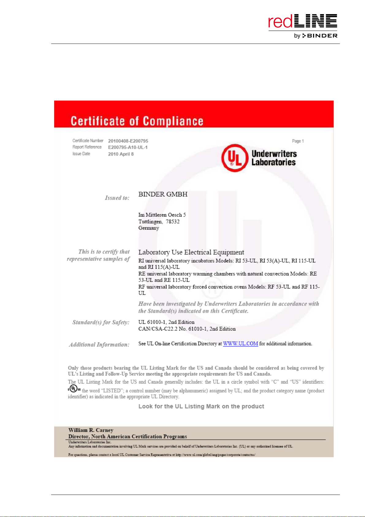
UL certificate, valid for redLINE-UL units......................................................................................................8
1. SAFETY................................................................................................................11
1.1 Legal considerations .........................................................................................................................11
1.2 Structure of the safety instructions....................................................................................................11
1.2.1 Signal word panel ........................................................................................................................11
1.2.2 Safety alert symbol ......................................................................................................................12
1.2.3 Pictograms ...................................................................................................................................12
1.2.4 Word message panel structure....................................................................................................13
1.3 Localization / position of safety labels on the unit.............................................................................13
1.4 Type plate .........................................................................................................................................14
1.5 General safety instructions on installing and operating the redLINE chambers...............................15
1.6 Intended use .....................................................................................................................................16
2. UNIT DESCRIPTION............................................................................................17
2.1 Scope of delivery...............................................................................................................................17
2.2 Equipment overview..........................................................................................................................18
2.3 Control panel.....................................................................................................................................19
3. SCOPE OF DELIVERY, TRANSPORTATION, STORAGE, AND INSTALLATION19
3.1 Unpacking, and checking equipment and scope of delivery.............................................................19
3.2 Guidelines for safe lifting and transportation ....................................................................................20
3.3 Storage..............................................................................................................................................20
3.4 Location of installation and ambient conditions ................................................................................20
3.5 Stacking ............................................................................................................................................21
4. INSTALLATION OF THE EQUIPMENT ...............................................................22
4.1 Electrical connection .........................................................................................................................22
4.2 Connection to a suction plant (optional) ...........................................................................................23
5. START UP............................................................................................................24
5.1 Adjusting the air change ...................................................................................................................24
5.2 Controller overview ...........................................................................................................................25
5.3 Turning on the unit ............................................................................................................................27
6. OPERATING THE CONTROLLER.......................................................................27
6.1 Operating modes...............................................................................................................................27
6.2 Operating mode Automatic Mode – entering the set-point ...............................................................29
6.3 Operating mode Manual Mode .........................................................................................................30
6.4 Timer operation.................................................................................................................................30
6.5 Setting the temperature unit..............................................................................................................32
7. CALIBRATING AND ADJUSTING THE TEMPERATURE CONTROLLER.........33
7.1 Required measuring equipment........................................................................................................33
7.2 Check (calibration) ............................................................................................................................33
7.3 Two-point adjustment procedure ......................................................................................................33
8. CLEANING AND DECONTAMINATION..............................................................37
8.1 Cleaning ............................................................................................................................................37
8.2 Decontamination ...............................................................................................................................38

Redline Operating Manual RE / RF / RI 12/2010 page 10/46
9. DECOMMISSIONING...........................................................................................38
10. MAINTENANCE ...................................................................................................39
10.1 Maintenance plan..............................................................................................................................39
11. TECHNICAL SERVICE.........................................................................................39
12. DISPOSAL............................................................................................................40
12.1 Disposal of the transport packing .....................................................................................................40
12.2 Disposal of redLINE chambers in the member states of the EC ......................................................40
12.3 Disposal of redLINE chambers in non-member states of the EC.....................................................41
13. TROUBLESHOOTING .........................................................................................42
14. TECHNICAL DESCRIPTION................................................................................43
14.1 Factory calibration and adjustment...................................................................................................43
14.2 Over current protection .....................................................................................................................43
14.3 Definition of usable volume...............................................................................................................43
14.4 redLINE technical data......................................................................................................................44
14.5 Equipment .........................................................................................................................................45

Redline Operating Manual RE / RF / RI 12/2010 page 11/46
Dear customer,
For the correct operation of the redLINE chambers, it is important that you read this operating manual
completely and carefully and observe all instructions as indicated. Failure to read, understand and follow
the instructions may result in personal injury. It can also lead to damage to the unit and/or poor
equipment performance
1. Safety
This operating manual is part of the components of delivery. Always keep it handy for reference. The
device should only be operated by laboratory personnel especially trained for this purpose and familiar
with all precautionary measures required for working in a laboratory. To avoid injuries and damage
observe the safety instructions of the operating manual.
WARNING
Failure to observe the safety instructions.
Serious injuries and unit damage.
¾Observe the safety instructions in this operating manual.
¾Carefully read the complete operating instructions of the redLINE chambers.
1.1 Legal considerations
This operating manual is for informational purposes only. It contains information for installing, start-up,
operation and maintenance of the product. Note: the contents and the product described are subject to
change without notice.
Understanding and observing the instructions in this operating manual are prerequisites for hazard-free
use and safety during operation and maintenance. In no event shall BINDER be held liable for any
damages, direct or incidental arising out of or related to the use of this manual.
This operating manual cannot cover all conceivable applications. If you would like additional information,
or if special problems arise that are not sufficiently addressed in this manual, please ask your dealer or
contact us directly by phone at the number located on page one of this manual
Furthermore, we emphasize that the contents of this operating manual are not part of an earlier or
existing agreement, description, or legal relationship, nor do they modify such a relationship. All
obligations on the part of BINDER derive from the respective purchase contract, which also contains the
entire and exclusively valid statement of warranty administration. The statements in this manual neither
augment nor restrict the contractual warranty provisions.
1.2 Structure of the safety instructions
In this operating manual, the following safety definitions and symbols indicate dangerous situations
following the harmonization of ISO 3864-2 and ANSI Z535.6.
1.2.1 Signal word panel
Depending on the probability of serious consequences, potential dangers are identified with a signal
word, the corresponding safety color, and if appropriate, the safety alert symbol.
DANGER
Indicates an imminently hazardous situation that, if not avoided, will result in death or serious
(irreversible) injury.

Redline Operating Manual RE / RF / RI 12/2010 page 12/46
WARNING
Indicates a potentially hazardous situation which, if not avoided, could result in death or serious
(irreversible) injury
CAUTION
Indicates a potentially hazardous situation which, if not avoided, may result in moderate or minor
(reversible) injury
CAUTION
Indicates a potentially hazardous situation which, if not avoided, may result in damage to the product
and/or its functions or of a property in its proximity.
1.2.2 Safety alert symbol
Use of the safety alert symbol indicates a risk of injury.
Observe all measures that are marked with the safety alert symbol in order to avoid death or
injury.
1.2.3 Pictograms
Warning signs
Electrical hazard
Hot surface
Explosive atmosphere
Stability hazard
Pollution Hazard
Harmful substances
Biohazard
Lifting hazard
Mandatory action signs
Mandatory regulation
Read operating
instructions
Disconnect the power
plug
Lift with several persons
Environment protection
Prohibition signs
Do NOT touch
Do NOT spray with
water

Redline Operating Manual RE / RF / RI 12/2010 page 13/46
Information to be observed in order to ensure optimum function of the product.
1.2.4 Word message panel structure
Type / cause of hazard.
Possible consequences.
∅Instruction how to avoid the hazard: prohibition.
¾Instruction how to avoid the hazard: mandatory action.
Observe all other notes and information not necessarily emphasized in the same way, in order to avoid
disruptions that could result in direct or indirect injury or property damage.
1.3 Localization / position of safety labels on the unit
The following labels are located on the unit:
Pictograms (Warning signs)
Hot surface
Risk of injury (UL units only)
redLINE redLINE-UL
Figure 1: Position of labels on the unit
Keep safety labels complete and legible.
Replace safety labels that are no longer legible. Call up www.binder-redline.com for these replacements.

Redline Operating Manual RE / RF / RI 12/2010 page 14/46
1.4 Type plate
The type plate is located on the left-hand side of the unit, bottom right-hand.
Figure 2: Type plate (example: RE 53)
Indications of the type plate Information
Nominal temperature 220 °C
428°F
Nominal temperature
Enclosure protection IP 20 IP type of protection 20 acc. to EN 60529
Art. No. 9090-0001 Article number 9090-0001
0,80 kW Nominal power 0.80 kW
230 V 1 N ~ Nominal voltage 230 V ±10%, single-phase unit
3,5 A Nominal current 3.5 Amp
50/60 Hz Power frequency 50/60 Hz
RE 53 Model RE 53
Serial No. RE-000000-00000 Serial No. RE-000000-00000
Symbol on the type plate Information
CE conformity marking
Electrical and electronic equipment manufactured / placed on
the market in the EC after 13 August 2005 and to be disposed
of in a separate collection according to directive 2002/96/EC
on waste electrical and electronic equipment (WEEE).
LABORATORY EQUIPMENT
43KM
(UL units only)
The equipment is certified by Underwriters Laboratories Inc.®
according to standards CAN/CSA-C22.2 No. 61010-1, 2nd
Edition, 2004-07 (Electrical Equipment for Measurement,
Control, and Laboratory Use; Part 1: General Requirements);
UL 61010-1, 2nd Edition, 2005-07-22 (Electrical Equipment for
Measurement, Control, and Laboratory Use; Part 1: General
Requirements); IEC 61010-1:2001, 2nd Edition and IEC 61010-
2-10 (Particular Requirements for Laboratory Equipment for
the heating of materials).
Nominal temperature 220 °C 0,80
kW
428°F 230
V 1 N ~
Enclosure protection
Art. No.
IP 20
9090-0001
3,5
50/60
A
Hz
RE 53 Serial No. RE-000000-00000
www.binder-redline.com Made by BINDER in Germany

Redline Operating Manual RE / RF / RI 12/2010 page 15/46
1.5 General safety instructions on installing and operating the redLINE
chambers
With regard to operating the redLINE chambers and to their installation location, please observe the
guideline BGI/GUV-I on safe working in laboratories (formerly BGR/GUV-R 120 or ZH 1/119 laboratory
guidelines issued by the employers’ liability insurance association) (for Germany).
The manufacturer is only responsible for the safety features of the unit provided skilled electricians or
qualified personnel authorized by the manufacturer perform all maintenance and repair, and if
components relating to chamber safety are replaced in the event of failure with original spare parts.
To operate the unit, use only original accessories or accessories from third-party suppliers authorized by
the manufacturer. The user is responsible for any risk caused by using unauthorized accessories.
CAUTION
Danger of overheating.
Damage to the unit.
∅Do NOT install redLINE chambers in unventilated recesses.
¾Ensure sufficient ventilation for dispersal of the heat.
Do not operate the redLINE chambers in hazardous locations.
DANGER
Explosion hazard.
Danger of death.
∅Do NOT operate redLINE chambers in potentially explosive areas.
¾KEEP explosive dust or air-solvent mixtures AWAY from the unit.
The redLINE chambers do not dispose of any measures of explosion protection.
DANGER
Explosion hazard.
Danger of death.
∅Do NOT introduce any substance into the redLINE chambers which is combustible or
explosive at working temperature.
∅NO explosive dust or air-solvent mixture in the inner chamber.
Any solvent contained in the charging material must not be explosive or inflammable. I.e., irrespective of
the solvent concentration in the steam room, NO explosive mixture with air must form. The temperature
inside the chamber must lie below the flash point or below the sublimation point of the charging material.
Familiarize yourself with the physical and chemical properties of the charging material, as well as the
contained moisture constituent and its behavior with the addition of heat energy.
Familiarize yourself with any potential health risks caused by the charging material, the contained
moisture constituent or by reaction products that may arise during the temperature process. Take
adequate measures to exclude such risks prior to putting the unit into operation.

Redline Operating Manual RE / RF / RI 12/2010 page 16/46
DANGER
Electrical hazard.
Danger of death.
∅The unit must NOT become wet during operation or maintenance.
redLINE chambers were produced in accordance with VDE regulations and were routinely tested in
accordance to VDE 0411-1 (IEC 61010-1).
CAUTION
The inner chamber and the outgoing air pipe will become hot during operation.
Danger of burning.
∅Do NOT touch the inner surfaces, the access ports, or the charging material during
operation.
1.6 Intended use
Gravity convection ovens RE and mechanical convection ovens RF are designed for all standard
drying and tempering tasks as well as sterilizing glassware. They are intended for use in biological,
chemical, medical, pharmaceutical and physical laboratories.
Incubators RI are designed to cultivate microorganisms at defined temperatures. They can be used e. g.
for determining the number of microorganisms through plate count methods or detecting of pathogenic
germs, e.g. in product samples. They are intended for use in biological, chemical, medical, and
pharmaceutical laboratories.
Any solvent content must not be explosive or flammable. A mixture of any component of the charging
material with air must NOT be explosive. The operating temperature must lie below the flash point or
below the sublimation point of the charging material.
Other applications are not approved.
Do NOT use redLINE chambers for drying purpose if greater quantities of steam leading to condensation
will be set free.
Following the instructions in this operating manual and conducting regular maintenance work
(chap. 10) are part of the intended use.
Due to the special demands of the Medical Device Directive (MDD) this ovens are not qualified for
sterilization of medical devices as defined by the directive 93/42/EWG.

Redline Operating Manual RE / RF / RI 12/2010 page 17/46
2. Unit description
Function
Gravity convection ovens RE and mechanical convection ovens RF are suitable for drying and heat
treatment of solid or pulverized charging material, as well as bulk material, using the supply of heat. They
are designed for all standard drying and tempering tasks as well as sterilizing glassware. RF permits
shorter drying times.
The incubators RI are designed for exact temperation of harmless materials. They are designed to
cultivate microorganisms at defined temperatures.
Controller
redLINE chambers are equipped with an electronic PID-controller with digital display. The ovens RE and
RF have a temperature display and setting with an accuracy of one degree. The incubators RI have a
temperature display and setting with an accuracy of a tenth of a degree. The integrated timer can be set
to 0-9999 minutes. Also continuous operation is possible.
Interior and housing
The inner chamber, the pre-heating chamber and the inside of the doors are all made of stainless steel.
When operating the ovens RE and RF at temperatures above 150 °C / 302°F, the impact of the oxygen in
the air may cause discoloration of the metallic surfaces (yellowish-brown or blue) by natural oxidation
processes. These colorations are harmless and will in no way impair the function or quality of the unit.
The housing is RAL 7035 powder-coated. All corners and edges are also completely coated.
Heating and ventilation
redLINE chambers are heated electrically and ventilated naturally. Mechanical convection ovens RF are
ventilated by fan-assisted, forced-air circulation. The direct heating system provides an extremely precise
internal temperature. A thermoelement serves to measure the tempering of the interior, which is
controlled by the redline controller.
Temperature range: Ovens RE and RF: by 7 °C / 12°F above room temperature up to 220 °C / 428°F.
Incubators RI: by 7 °C / 12°F above room temperature up to 70 °C / 158°F.
Temperature safety device
redLINE chambers are equipped with a temperature safety device class 1 according to DIN12880. The
temperature fuse is triggered irreversibly if the maximum temperature of 229 °C / 444.2°F (RE, RF) resp.
110 °C / 230°F (RI) inside the chamber is exceeded.
Electrical connection
redLINE chambers are available for a 230 V, redLINE UL chambers for a 100-120 V power supply.
2.1 Scope of delivery
•redLINE gravity convection oven RE, or redLINE mechanical convection oven RF, or redLINE
incubator RI
•2 trays
•Flat assembly bar for stacking (it is vital to keep them, as two flat assembly bars are required to stack
two devices, and each device comes supplied with one)

Redline Operating Manual RE / RF / RI 12/2010 page 18/46
2.2 Equipment overview
Figure 3: redLINE gravity convection oven RE
Figure 4: redLINE mechanical convection oven RF
Figure 5: redLINE incubator RI
(1) Chamber door
(2) Door handle
(3) Controller
(4) Tray
(5) Inner glass door
(1)
(2)
(3)
(1)
(2)
(3)
(1)
(3)
(4)
(5)
(4)
(4)

Redline Operating Manual RE / RF / RI 12/2010 page 19/46
2.3 Control panel
The control panel with the controller and the main power switch is located on the housing below the door.
(6) Controller
(7) Main power switch
Figure 6: redLINE control panel
3. Scope of delivery, transportation, storage, and installation
3.1 Unpacking, and checking equipment and scope of delivery
After unpacking, please check the redLINE chamber and its optional accessories, if any, based on the
delivery note for completeness and for transportation damage. If transportation damage has occurred,
inform the carrier immediately and have it confirmed on the proof of delivery by the vehicle driver who
delivers the equipment.
The final tests of the manufacturer may cause traces of the trays on the inner surfaces. This has no
impact on the function and performance of the unit.
Please remove any transportation protection devices and adhesives in/on the unit and on the doors and
take out the operating manuals and accessory equipment.
CAUTION
Sliding or tilting of the unit.
Damage to the unit.
Risk of injury by lifting heavy loads.
∅Do NOT lift or transport a redLINE chamber using the door handle or the door.
¾Lift a redLINE chamber from the pallet at its four lower corners with the aid of 2 people.
In case of warranty please contact www.binder-redline.com.
For disposal of the transport packing, see chap. 12.1.
(6)
(7)

Redline Operating Manual RE / RF / RI 12/2010 page 20/46
3.2 Guidelines for safe lifting and transportation
Observe the advice for temporal decommissioning (chap. 9).
CAUTION
Sliding or tilting of the unit.
Damage to the unit.
Risk of injury by lifting heavy loads.
¾Transport the redLINE chamber in its original packaging only.
¾Secure the redLINE chamber with transport straps for transport.
∅Do NOT lift or transport a redLINE chamber using the door handle or the door.
¾Lift a redLINE chamber at its four lower corners with the aid of 2 people and place it on
a transport pallet with wheels. Push the pallet to the desired site and then lift the unit
from the pallet at its four lower corners.
•Permissible ambient temperature range during transport: -10 °C / 14°F to +60 °C / 140°F.
You can order transport packing and pallets for transportation purposes via www.binder-redline.com.
3.3 Storage
Intermediate storage of the unit is possible in a closed and dry room. Observe the guidelines for
temporary decommissioning (chap. 9).
•Permissible ambient temperature range during storage: -10 °C / 14°F to +60 °C / 140°F.
•Permissible ambient humidity: max. 70 % r.H., non-condensing
If following storage in a cold location the unit is transferred to the installation site for start-up,
condensation may form. Wait at least one hour until the oven has attained ambient temperature and is
completely dry.
3.4 Location of installation and ambient conditions
Set up the redLINE chamber on a flat, even, and non-flammable surface, free from vibration and in a well-
ventilated, dry location and align them using a spirit level. The site of installation must be capable of
supporting the unit’s weight (see technical data, chap. 14.4). The chambers are designed for setting up
inside a building (indoor use). Set up the chamber in such a way that the main power switch (7) is easily
accessible and can be turned off immediately in case of danger.
CAUTION
Danger of overheating.
Damage to the unit.
∅Do NOT set up redLINE chambers in non-ventilated recesses.
¾Ensure sufficient ventilation for dispersal of the heat.
•Permissible ambient temperature range during operation: +18 °C / 64.4°F up to +40 °C / 104°F. At
elevated ambient temperature values, fluctuations in temperature can occur.
The ambient temperature should not be substantially higher than the indicated ambient
temperature of +25 °C / 77°F to which the specified technical data relate. For other
ambient conditions, deviations from the indicated data are possible.
This manual suits for next models
11
Table of contents
Popular Convection Oven manuals by other brands

GE
GE Profile JVM1790 owner's manual

Monogram
Monogram ZET2S owner's manual

Jenn-Air
Jenn-Air SCE70600 use and care manual

Kitchen Monkey
Kitchen Monkey KMCOH-2670W manual

Crown Food Service Equipment
Crown Food Service Equipment DCX-16 Installation & operation manual

IKEA
IKEA STANDARD CLEANING BUILT-INELECTRIC CONVECTION... Use & care guide

Blodgett
Blodgett CTB SERIES Installation operation & maintenance

Blodgett
Blodgett DFG-100 Series Specifications

Siemens
Siemens avantGarde SKU HB30D50U features and benefits

Lamona
Lamona LAM3207 User's installation guide

Jenn-Air
Jenn-Air JMW3430 Use and care guide

Blue Seal
Blue Seal turbofan E311 Service manual