Binder VAP 1 User manual

Issue 06/2020 Art. No. 7001-0397
Operating Manual
Translation of the original operating manual
Vacuum pump VAP 1 / VAP 2
For vacuum drying oven VD
Model Voltage Equipment Art. no.
Vacuum pump VAP 1 230 V 2 heads 5013-0217
Vacuum pump VAP 1 120 V 2 heads 5013-0223
Vacuum pump VAP 2 230 V 4 heads 5013-0218
Vacuum pump VAP 2 120 V 4 heads 5013-0219
BINDER GmbH
Address: Post office box 102, 78502 Tuttlingen, Germany Phone: +49 7462 2005 0
Fax: +49 7462 2005 100 Internet: http://www.binder-world.com
E-mail: info@binder-world.com Service Hotline: +49 7462 2005 555
Service Fax: +49 7462 2005 93 555 Service E-Mail: service@binder-world.com
Service Hotline USA: +1 866 885 9794 or +1 631 224 4340 x3
Service Hotline Asia Pacific: +852 390 705 04 or +852 390 705 03
Service Hotline Russia and CIS: +7 495 988 15 16

VAP 1 / VAP 2 06/2020 Page 2/52
Contents
1. SAFETY..................................................................................................................4
1.1 Personnel Qualification.......................................................................................................................4
1.2 Operating manual................................................................................................................................4
1.3 Legal considerations...........................................................................................................................4
1.4 Structure of the safety instructions......................................................................................................5
1.4.1 Signal word panel .....................................................................................................................5
1.4.2 Safety alert symbol ...................................................................................................................5
1.4.3 Pictograms................................................................................................................................6
1.4.4 Word message panel structure.................................................................................................6
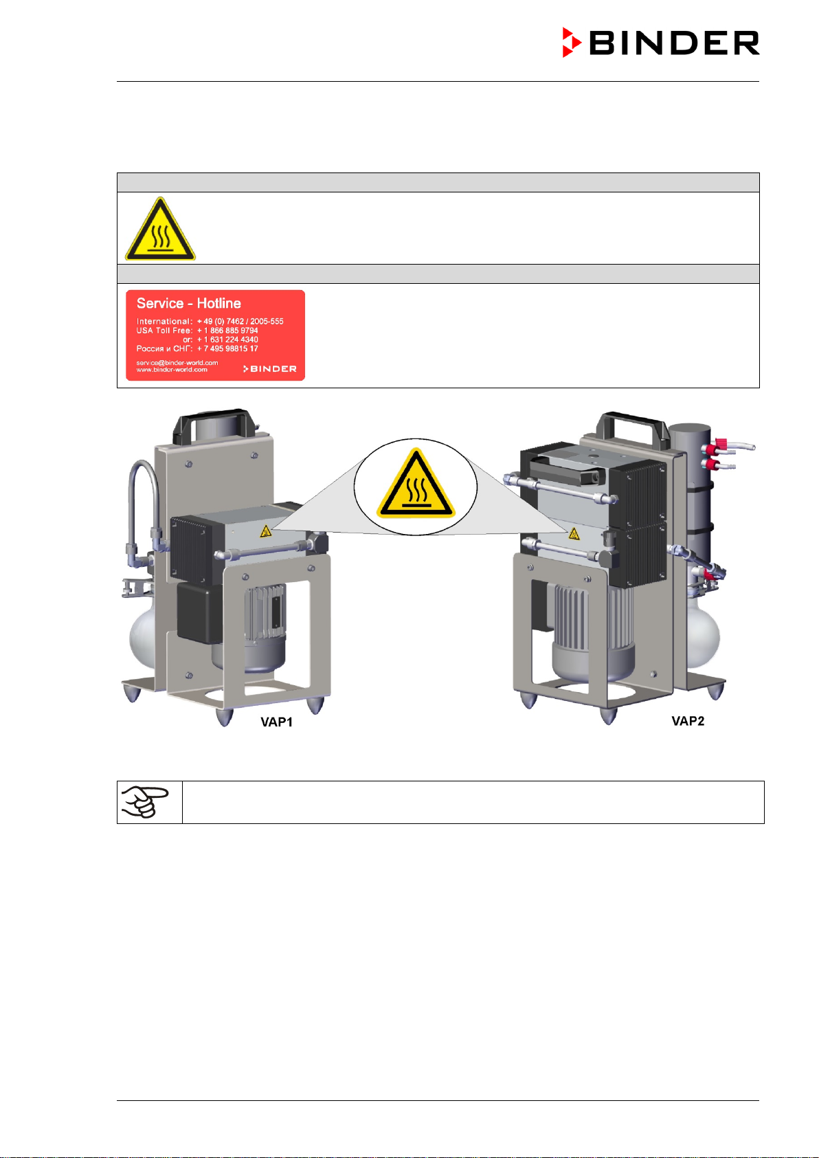
1.5 Localization / position of safety labels on the device..........................................................................7
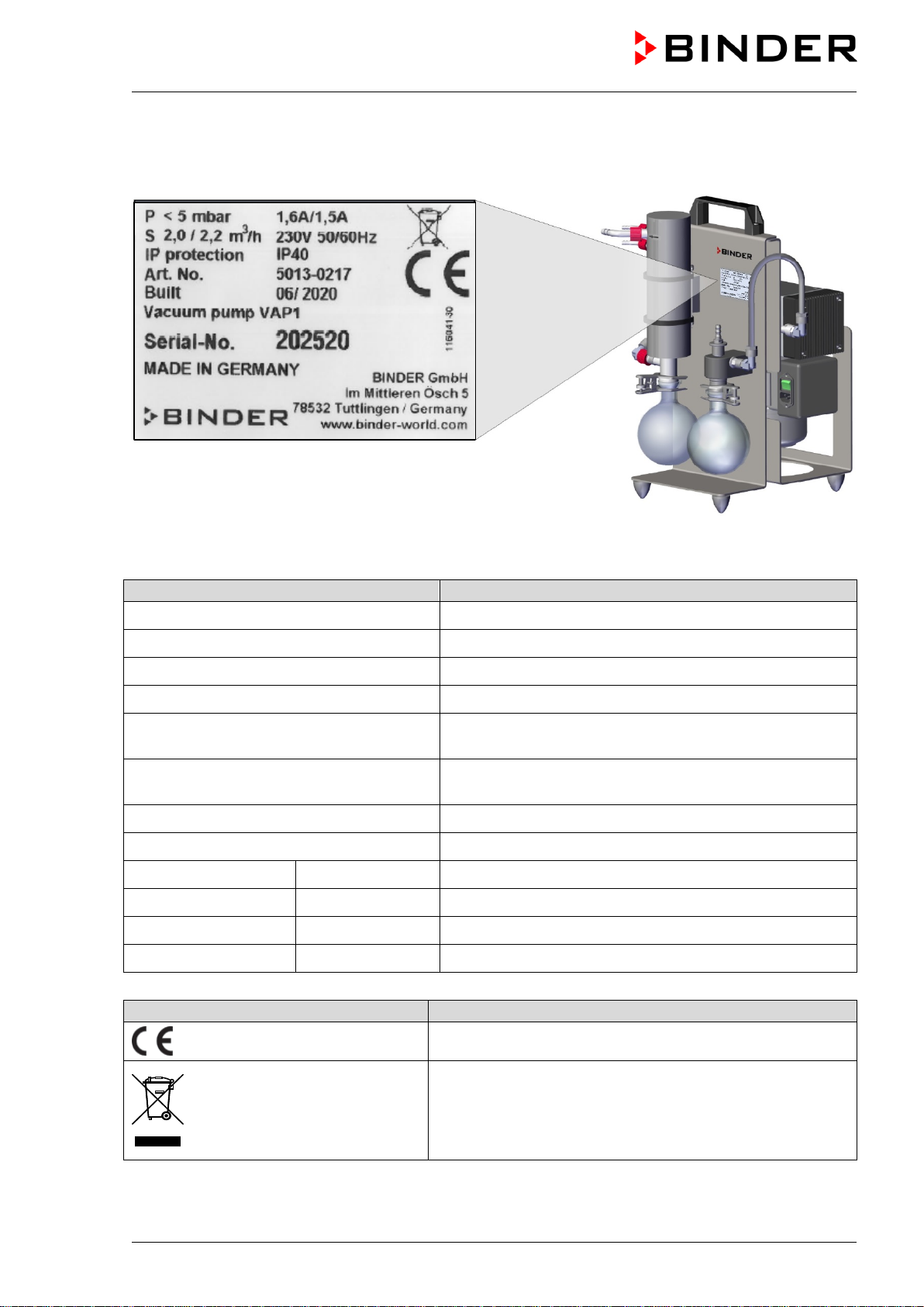
1.6 Type plate............................................................................................................................................8
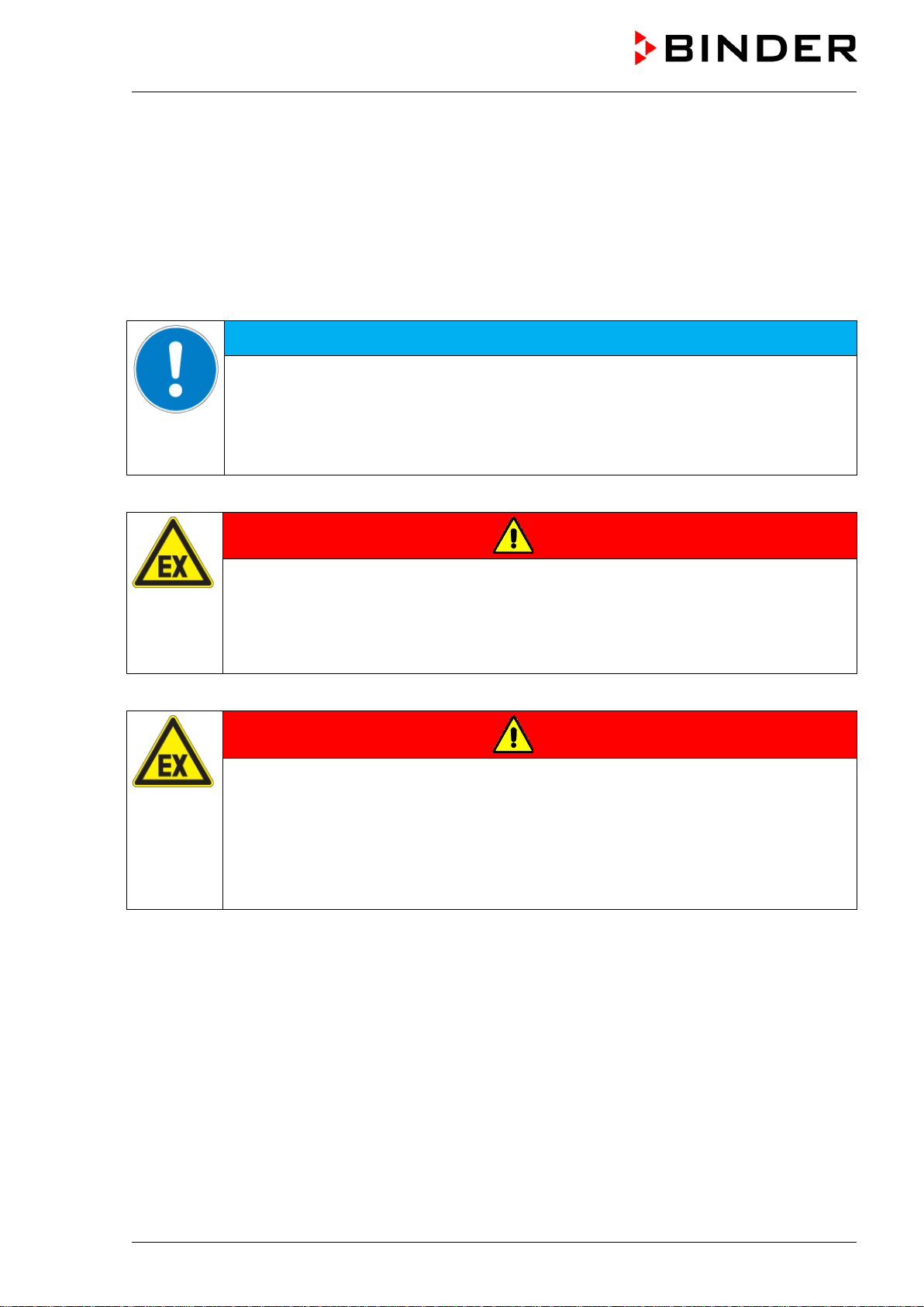
1.7 General safety instructions on installing and operating......................................................................9
1.8 Intended use .....................................................................................................................................11
1.9 Foreseeable Misuse..........................................................................................................................12
1.10 Residual Risks ..................................................................................................................................13
1.11 Operating instructions .......................................................................................................................14
1.12 Measures to prevent accidents.........................................................................................................15
2. DEVICE DESCRIPTION.......................................................................................16
2.1 Device overview................................................................................................................................17
3. COMPLETENESS OF DELIVERY, TRANSPORTATION, STORAGE, AND
INSTALLATION....................................................................................................18
3.1 Scope of delivery...............................................................................................................................18
3.2 Unpacking, and checking the equipment..........................................................................................18
3.3 Assembly...........................................................................................................................................19
3.4 Guidelines for safe transportation.....................................................................................................20
3.5 Storage..............................................................................................................................................20
3.6 Location of installation and ambient conditions ................................................................................20
4. INSTALLATION AND CONNECTIONS ...............................................................21
4.1 Vacuum connection...........................................................................................................................21
4.2 Electrical connection.........................................................................................................................23
5. START UP............................................................................................................24
5.1 Turning on the device........................................................................................................................24
5.2 Adjusting the gas ballast...................................................................................................................25
6. OPERATION.........................................................................................................25
6.1 Daily inspection.................................................................................................................................25
6.2 Removing and emptying the condensate catchpot...........................................................................26
7. CLEANING AND DECONTAMINATION..............................................................26
7.1 Cleaning............................................................................................................................................27
7.2 Decontamination / chemical disinfection of the device .....................................................................28
8. MAINTENANCE AND SERVICE, TROUBLESHOOTING, REPAIR, TESTING...29
8.1 General information, personnel qualification.....................................................................................29
8.2 Maintenance intervals, service..........................................................................................................30
8.3 Simple troubleshooting......................................................................................................................30
8.4 Maintenance by the operator ............................................................................................................31
8.4.1 Replacing the form diaphragm, valves, and O-rings ..............................................................32
8.4.2 Function test ...........................................................................................................................34
8.5 Sending the device back to BINDER GmbH.....................................................................................34

VAP 1 / VAP 2 06/2020 Page 3/52
9. DISPOSAL............................................................................................................35
9.1 Disposal of the transport packing......................................................................................................35
9.2 Decommissioning..............................................................................................................................35
9.3 Disposal of the device in the Federal Republic of Germany.............................................................35
9.4 Disposal of the device in the member states of the EU except for the Federal Republic of Germany36
9.5 Disposal of the device in non-member states of the EU...................................................................37
10. TECHNICAL DESCRIPTION................................................................................38
10.1 Technical data...................................................................................................................................38
10.2 Circuit of the pump heads.................................................................................................................39
10.3 Connections ......................................................................................................................................39
10.4 Materials of pump parts in contact with the medium.........................................................................39
10.5 Accessories and spare parts (extract) ..............................................................................................40
10.6 Diagrams of suction pressure / pumping speed................................................................................41
10.7 Dimensions........................................................................................................................................42
11. CERTIFICATES AND DECLARATIONS OF CONFORMITY...............................43
11.1 EU Declaration of conformity ............................................................................................................43
12. PRODUCT REGISTRATION................................................................................46
13. CONTAMINATION CLEARANCE CERTIFICATE ...............................................47
13.1 For devices located outside the USA and Canada...........................................................................47
13.2 For devices in the USA and Canada.................................................................................................50

VAP 1 / VAP 2 06/2020 Page 4/52
Dear customer,
For the correct operation of the vacuum pump, it is important that you read this operating manual
completely and carefully and observe all instructions as indicated. Failure to read, understand and follow
the instructions may result in personal injury. It can also lead to damage to the device and/or poor
equipment performance.
1. Safety
1.1 Personnel Qualification
The device must only be installed, tested, and started up by personnel qualified for assembly, startup,
and operation of the device. Qualified personnel are persons whose professional education, knowledge,
experience and knowledge of relevant standards allow them to assess, carry out, and identify any
potential hazards in the work assigned to them. They must have been trained and instructed, and be
authorized, to work on the device.
The device should only be operated by laboratory personnel especially trained for this purpose and
familiar with all precautionary measures required for working in a laboratory. Observe the national
regulations on minimum age of laboratory personnel.
1.2 Operating manual
This operating manual is part of the components of delivery. Always keep it handy for reference in the
vicinity of the device. If selling the unit, hand over the operating manual to the purchaser.
To avoid injuries and damage observe the safety instructions of the operating manual. Failure to follow
instructions and safety precautions can lead to significant risks.
DANGER
Dangers due to failure to observe the instructions and safety precautions.
Serious injuries and device damage. Risk of death.
Observe the safety instructions in this Operating Manual.
Follow the operating procedures in this Operating Manual.
Carefully read the complete operating instructions of the device prior to installing and
using the device.
Keep the operating manual for future reference
Make sure that all persons who use the device and its associated work equipment have read
and understood the Operating Manual.
This Operating Manual is supplemented and updated as needed. Always use the most recent version of
the Operating Manual. When in doubt, call the BINDER Service Hotline for information on the up-to-
dateness and validity of this Operating Manual.
1.3 Legal considerations
This operating manual is for informational purposes only. It contains information for correct and safe
installing, start-up, operation, decommissioning, cleaning and maintenance of the product. Note: the
contents and the product described are subject to change without notice.

VAP 1 / VAP 2 06/2020 Page 5/52
Understanding and observing the instructions in this operating manual are prerequisites for hazard-free
use and safety during operation and maintenance. Images are to provide basic understanding. They may
deviate from the actual version of the device. The actual scope of delivery can, due to optional or special
design, or due to recent technical changes, deviate from the information and illustrations in these
instructions this operating manual. In no event shall BINDER be held liable for any damages, direct or
incidental arising out of or related to the use of this manual.
This operating manual cannot cover all conceivable applications. If you would like additional information,
or if special problems arise that are not sufficiently addressed in this manual, please ask your dealer or
contact us directly, e.g. by phone at the number located on page one of this manual
Furthermore, we emphasize that the contents of this operating manual are not part of an earlier or
existing agreement, description, or legal relationship, nor do they modify such a relationship. All
obligations on the part of BINDER derive from the respective purchase contract, which also contains the
entire and exclusively valid statement of warranty administration and the general terms and conditions, as
well as the legal regulations valid at the time the contract is concluded. The statements in this manual
neither augment nor restrict the contractual warranty provisions.
1.4 Structure of the safety instructions
In this operating manual, the following safety definitions and symbols indicate dangerous situations
following the harmonization of ISO 3864-2 and ANSI Z535.6.
1.4.1 Signal word panel
Depending on the probability of serious consequences, potential dangers are identified with a signal
word, the corresponding safety color, and if appropriate, the safety alert symbol.
DANGER
Indicates an imminently hazardous situation that, if not avoided, will result in death or serious
(irreversible) injury.
WARNING
Indicates a potentially hazardous situation which, if not avoided, could result in death or serious
(irreversible) injury.
CAUTION
Indicates a potentially hazardous situation which, if not avoided, may result in moderate or minor
(reversible) injury.
NOTICE
Indicates a potentially hazardous situation which, if not avoided, may result in damage to the product
and/or its functions or of a property in its proximity.
1.4.2 Safety alert symbol
Use of the safety alert symbol indicates a risk of injury.
Observe all measures that are marked with the safety alert symbol in order to avoid death or
injury.

VAP 1 / VAP 2 06/2020 Page 6/52
1.4.3 Pictograms
Warning signs
Electrical hazard
Hot surface
Explosive atmosphere
Stability hazard
Lifting hazard
Risk of corrosion and /
or chemical burns
Risk of cuts
Harmful substances
Biohazard
Pollution Hazard
Mandatory action signs
Mandatory regulation
Read operating
instructions
Disconnect the power
plug
Environment protection
Wear protective gloves
Wear safety goggles
Prohibition signs
Do NOT touch
Do NOT spray with
water
Do NOT climb
Information to be observed in order to ensure optimum function of the product.
1.4.4 Word message panel structure
Type / cause of hazard.
Possible consequences.
Instruction how to avoid the hazard: prohibition
Instruction how to avoid the hazard: mandatory action
Observe all other notes and information not necessarily emphasized in the same way, in order to avoid
disruptions that could result in direct or indirect injury or property damage.

VAP 1 / VAP 2 06/2020 Page 7/52
1.5 Localization / position of safety labels on the device
The following labels are located on the pump motor housing:
Pictograms (warning signs)
Hot surface
Service label
Figure 1: Position of the “Hot surface” safety label on the unit
Keep safety labels complete and legible.
Replace safety labels that are no longer legible. Contact BINDER service for these replacements.

VAP 1 / VAP 2 06/2020 Page 8/52
1.6 Type plate
Figure 2: Type plate (example: VAP 1 230 V 5013-0217) and position of on the pump
Indications on the type plate (example)
Information
BINDER Manufacturer: BINDER GmbH
VAP 1 Model designation
Vacuum pump Device name
P < 5 mbar Final pressure
S 2,0 / 2,2 m3/h Suction capacity
(2.0 m3/h at 50 Hz; 2.2 m3/h at 60 Hz)
1,6 A / 1,5 A Rated current
(1.6 A at 50 Hz; 1.5 A at 60 Hz)
230 V 50/60 Hz Nominal voltage +/-10% at the indicated power frequency
1 N ~ Current type
IP protection IP40 IP type of protection acc. to standard EN 60529
Art. No. 5013-0217 Art. No. of the device
Built 06/2020 Year of construction
Serial No. 202299 Serial no. of the device (example)
Symbol on the type plate
Information
CE conformity marking
Electrical and electronic equipment manufactured / placed
on the market in the EC after 13 August 2005 and to be
disposed of in separate collection according to Directive
2012/19/EU on waste electrical and electronic equipment
(WEEE).

VAP 1 / VAP 2 06/2020 Page 9/52
1.7 General safety instructions on installing and operating
With regard to operating the device and to the installation location, please observe the guideline
BGI/GUV-I 850-0 on safe working in laboratories (for Germany).
BINDER GmbH is only responsible for the safety features of the device provided skilled electricians or
qualified personnel authorized by BINDER perform all maintenance and repair, and if components
relating to device safety are replaced in the event of failure with original spare parts.
To operate the device, use only original BINDER accessories or accessories from third-party suppliers
authorized by BINDER. The user is responsible for any risk caused by using unauthorized accessories.
NOTICE
Danger of overheating due to lack of ventilation.
Damage to the device.
∅Do NOT install the device in unventilated recesses.
Ensure sufficient ventilation for dispersal of the heat.
Observe the prescribed minimum distances when installing the pump (chap. 3.6)
Do not operate the device in hazardous locations.
DANGER
Danger of explosion due to combustible dusts or explosive mixtures in the vicinity
of the device.
Serious injury or death from burns and / or explosion pressure.
∅Do NOT operate the device in potentially explosive areas.
KEEP combustible dust or air-solvent mixtures AWAY from the device.
The device does not dispose of any measures of explosion protection.
DANGER
Danger of explosion due to aspirating flammable or explosive substances in the
device.
Serious injury or death from burns and / or explosion pressure.
∅Make sure that NO gases and vapors which are combustible or explosive at working
temperature are aspirated.
∅Make sure that NO combustible dust or air-solvent mixture will be in the inner chamber
of the vacuum drying oven.
Any solvent contained in gases and vapors must not be explosive or inflammable. I.e., irrespective of the
solvent concentration in the steam room, NO explosive mixture with air must form.
Familiarize yourself with any potential health risks caused by aspirated gases and vapors, the contained
moisture constituent. Take adequate measures to exclude such risks prior to putting the device into
operation.

VAP 1 / VAP 2 06/2020 Page 10/52
DANGER
Electrical hazard by water entering the device.
Deadly electric shock.
∅The device must NOT become wet during operation, cleaning, or maintenance.
∅Do NOT install the device in damp areas or in puddles.
Set up the device in a splash-proof manner.
The devices were produced in accordance with VDE regulations and were routinely tested in accordance
to VDE 0411-1 (IEC 61010-1).
During and after operation the motor housing becomes hot. Avoid touching the hot motor housing when
operating the pump, especially when using the on/off switch.
CAUTION
Danger of burning by touching hot areas during or after operation.
∅Do NOT touch the motor housing during and adjacent areas operation, especially when
using the on/off switch.
Figure 3: Hot areas on the vacuum pump

VAP 1 / VAP 2 06/2020 Page 11/52
1.8 Intended use
Following the instructions in this operating manual and conducting regular maintenance work
(chap. 8.2) are part of the intended use.
Any use of the devices that does not comply with the requirements specified in this Operating
Manual shall be considered improper use.
All applications must be within the specification (see Technical data, chap. 10.1 and indications on the
type plate, chap. 1.6).
Other applications than those described in this chapter are not approved.
Use
The diaphragm pumps VAP 1 and VAP 2 are suitable for extracting, conveying and compressing
harmless gases and vapors.
The diaphragm pumps are intended for:
•Creating vacuum
•Use in physical and chemical laboratories in trade or industry
•Use for vacuum filtration, vacuum distillation and vacuum drying as well as other applications in
vacuum technology
The devices are suitable for exact conditioning of harmless materials.
Requirements for the aspirated atmosphere
Aspirated gases and vapors must not be toxic, chemically aggressive or explosive. Any solvent must not
be explosive and flammable. Components of the gases and vapors must NOT form an explosive mixture
with air and NOT be able to release toxic gases.
Aspirated gases and vapors shall not contain any corrosive ingredients that may damage the machine
components. Such ingredients include in particular acids and halides. Any corrosive damage caused by
such ingredients is excluded from liability by BINDER GmbH.
The temperature of the aspirated gases and vapors must not exceed the permissible gas inlet
temperature of max. 40 °C / 104°F when entering the pump.
The pump is not suitable for aspirating liquids.
The device does not dispose of any measures of explosion protection.
DANGER
Explosion or implosion hazard and danger of poisoning through the aspiration of
unsuitable gases and vapors.
Poisoning. Serious injury or death from burns and / or explosion pressure.
∅Make sure that NO substance combustible or explosive at working temperature
can be
aspirated.
∅Make sure that NO explosive dust or air-solvent mixture can be aspirated.
∅Make sure that NO substance can be aspirated, which could lead to release of toxic
gases.

VAP 1 / VAP 2 06/2020 Page 12/52
Contamination of the device by toxic, infectious or radioactive substances must be prevented
WARNING
Danger of intoxication and infection through contamination of the chamber with
toxic, infectious or radioactive substances.
Damages to health.
Make sure that NO toxic, infectious or radioactive substances can be aspirated.
Take suitable protective measures when introducing and removing accidentally
aspirated toxic, infectious or radioactive material.
Solid particles in the aspirated medium impair the pumping action and can damage the pump.
NOTICE
Danger of mechanical damage and malfunctions due to the suction of solid
particles.
Damage to the device.
Prevent solid particles from entering the pump.
In case of foreseeable use of the device there is no risk for the user through the integration of the device
into systems or by special environmental or operating conditions in the sense of EN 61010-1:2010. For
this, the intended use of the device and all its connections must be observed.
Medical devices
The devices are not classified as medical devices as defined by the Medical Device Directive 93/42/EEC.
Due to the special demands of the Medical Device Directive (MDD), these devices are not
qualified for sterilization of medical devices as defined by the directive 93/42/EWG.
Personnel Requirements
Only trained personnel with knowledge of the Operating Manual can set up and install the device, start it
up, operate, clean, and take it out of operation. Service and repairs call for further technical requirements
(e.g. electrical know-how), as well as knowledge of the service manual.
Installation site requirements
The devices are designed for setting up inside a building (indoor use).
The requirements described in the Operating Manual for installation site and ambient conditions (Chap.
3.6) must be met
WARNING: If customer should use a BINDER device running in non-supervised continuous
operation, we strongly recommend in case of inclusion of irrecoverable specimen or samples
to split such specimen or samples and store them in at least two devices, if this is feasible.
1.9 Foreseeable Misuse
Other applications than those described in chap. 1.8 are not approved.
This expressly includes the following misuses (the list is not exhaustive), which pose risks despite the
inherently safe construction and existing technical safety equipment:
•Non-observance of Operating Manual
•Non-observance of safety labels on the device
•Installation, startup, operation, maintenance and repair by untrained, insufficiently qualified, or
unauthorized personnel

VAP 1 / VAP 2 06/2020 Page 13/52
•Missed or delayed maintenance and testing
•Non-observance of traces of wear and tear
•Aspiration of materials excluded or not permitted by this Operating Manual.
•Installation, testing, service or repair in the presence of solvents
•Installation of replacement parts and use of accessories and operating resources not specified and
authorized by the manufacturer
•Installation, startup, operation, maintenance or repair of the device in absence of operating
instructions provided by the operator
•Bypassing or changing protective systems, operation of the device without the designated protective
systems
•Non-observance of messages regarding cleaning and disinfection of the device.
•Spilling water or cleaning agent on the device, water penetrating into the device during operation,
cleaning or maintenance.
•Cleaning activity while device is switched on.
•Operation of the device with a damaged housing or damaged power cord
•Continued operation of the device during an obvious malfunction
•Insertion of objects, particularly metallic objects, in louvers or other openings or slots on the device
•Human error (e.g. insufficient experience, qualification, stress, exhaustion, laziness)
To prevent these and other risks from incorrect operation, the operator shall issue operating instructions.
Standard operating procedures (SOPs) are recommended.
1.10 Residual Risks
The unavoidable design features of a device, as well as its proper field of application, can also pose risks,
even during correct operation. These residual risks include hazards which, despite the inherently safe
design, existing technical protective equipment, safety precautions and supplementary protective
measures, cannot be ruled out.
Messages on the device and in the Operating Manual warn of residual risks. The consequences of these
residual risks and the measures required to prevent them are listed in the Operating Manual. Moreover,
the operator must take measures to minimize hazards from unavoidable residual risks. This includes, in
particular, issuing operating instructions.
The following list summarizes the hazards against which this Operating Manual and the Service Manual
warn, and specifies protective measures at the appropriate spots:
Unpacking, Transport, Installation
•Sliding or tilting the device
•Setup of the device in unauthorized areas
•Installation of a damaged device
•Installation of a device with damaged power cord
•Inappropriate site of installation
•Missing protective conductor connection
Normal operation
•Assembly errors
•Contact with hot surfaces on the housing

VAP 1 / VAP 2 06/2020 Page 14/52
•Contact with hot surfaces in the interior and inside of doors
•Emission of non-ionizing radiation from electrical operating resources
•Contact with live parts in normal state
Cleaning and Decontamination
•Penetration of water into the device
•Inappropriate cleaning and decontamination agents
Malfunction and Damage
•Continued operation of the device during an obvious malfunction or outage of the pump motor
•Contact with live parts during error status
•Operation of a unit with damaged power cord
Maintenance
•Maintenance work on live parts.
•Execution of maintenance work by untrained/insufficiently qualified personnel
•Electrical safety analysis during annual maintenance not performed
Trouble-shooting and Repairs
•Non-observance of warning messages in the Service Manual
•Trouble-shooting of live parts without specified safety measures
•Absence of a plausibility check to rule out erroneous inscription of electrical components
•Performance of repair work by untrained/insufficiently qualified personnel
•Inappropriate repairs which do not meet the quality standard specified by BINDER
•Use of replacement parts other than BINDER original replacement parts
•Electrical safety analysis not performed after repairs
1.11 Operating instructions
Depending on the application and location of the chamber, the operator of the chamber must provide the
relevant information for safe operation of the chamber in a set of operating instructions.
Keep these operating instructions with the chamber at all times in a place where they are
clearly visible. They must be comprehensible and written in the language of the employees.

VAP 1 / VAP 2 06/2020 Page 15/52
1.12 Measures to prevent accidents
The manufacturer took the following measures to prevent dangers:
•Indications on the type plate
See operating manual chap. 1.6.
•Operating manual
An operating manual is available for each device.
•Overtemperature monitoring
The device is equipped with a self-retaining thermal switch on the motor.
•Electrostatic charge
The interior parts are grounded.
The device is equipped with an IEC connector plug with a grounded plug. An electrical connection with
a protective conductor (operating mode S1: suitability for continuous operation) must be provided
(chap. 4.2).
•Non-ionizing radiation
Non-ionizing radiation is not intentionally produced, but released only for technical reasons by
electrical equipment (e.g. electric motors, power cables, solenoids). If persons with active implants
(e.g. pacemakers, defibrillators) keep a safe distance (distance of field source to implant) of 30 cm, an
influence of these implants can be excluded with high probability.
•Protection against touchable surfaces
Tested according to EN ISO 13732-1:2008.
•Floors
See operating manual chap. 3.6 for correct installation
•Cleaning
See operating manual chap. 6.2.

VAP 1 / VAP 2 06/2020 Page 16/52
2. Device description
The vacuum pump VAP 1 / VAP 2 serves to are used to extract harmless solvents from the VD vacuum
drying ovens from BINDER. The vacuum pumps are delivered with operating mode S1 (continuous
operation with constant load). During operation with the VD vacuum drying oven the pump runs in
continuous operation. The pressure control of the VD vacuum drying oven controls a valve to the
connected vacuum pump and so the set vacuum is reached.
All operating elements of the pump are easy and comfortable to use thanks to their clear arrangement.
Major features are easy cleaning of all chamber parts and easy connection.
Construction
The vacuum pump consists of the pump unit and drive motor. The pump unit includes the drive unit and
the pump heads. Each pump head contains form diaphragms and the working valves. The pump heads
face each other in a boxer arrangement. The pump heads are driven by an eccentric shaft with a
connecting rod.
Material
The housing made of steel FR235SRJR / KF12.03 and RAL 7035 powder-coated. All corners and edges
are also completely coated.
For the materials of pump parts in contact with the medium see chap. 10.4.
Temperature safety device
The device is equipped with am thermal switch located at the pump motor. This self-retaining bimetal
switch disconnects the entire pump when overheating. Reset is possible after cooling. To reset the
thermal switch, turn the device off and on by the main power switch (on / off switch).

VAP 1 / VAP 2 06/2020 Page 17/52
2.1 Device overview
Figure 4: Vacuum pump VAP 1 / VAP 2
(a) Tube to the VD vacuum drying oven
(b) Water connection for cooling IN or OUT
(c) Pressure connection
(d) Water connection for cooling IN or OUT
(e) Aspiration connection
(f) Fork clamp
(g) Condensate catchpot
(h) On/Off switch (main power switch) with power connection
(i) Pump unit
( j) Handle

VAP 1 / VAP 2 06/2020 Page 18/52
3. Completeness of delivery, transportation, storage, and installation
3.1 Scope of delivery
•Pump with small flange connection DN 16 KF
•2 condensate catchpots (glass flasks), packed separately
2 fork clamps (conical ground clamps) for condensate catchpots
Pneumatic connection (PTFE tube with 2 angle adjustment screws)
•Emission condenser with insulation, packed separately
2 fastening straps for emission condenser
•Hose nozzle DN 8
•Power cable with IEC connector plug
•Operating manual
3.2 Unpacking, and checking the equipment
Carefully unpack the vacuum pump VAP 1 / VAP 2.
After unpacking, please check the device and its optional accessories, if any, based on the delivery
receipt for completeness and for transportation damage. Inform the carrier immediately if transportation
damage has occurred.
The final tests of the manufacturer may have caused traces of the shelves on the inner surfaces. This has
no impact on the function and performance of the device.
Please remove any transportation protection devices and adhesives on the device and remove the
operating manuals and accessory equipment.
Remove the protective caps on the suction and pressure connections:
Dust protective cap for small flange connection
DN 16 KF (suction side) Protective sleeve for hose nozzle
(pressure side)
Figure 5: Protective caps on the suction and pressure connections
If you need to return the device, please use the original packing and observe the guidelines for safe lifting
and transportation (chap. 3.4).
For disposal of the transport packing, see chap. 9.1.

VAP 1 / VAP 2 06/2020 Page 19/52
Note on second-hand devices (Ex-Demo-Units):
Second-hand devices are devices that were used for a short time for tests or exhibitions. They are
thoroughly tested before resale. BINDER ensures that the device is technically sound and will work
flawlessly.
Second-hand devices are marked with a sticker. Please remove the sticker before commissioning the
device.
3.3 Assembly
Emission condenser
Fix the emission condenser with 2 fastening straps on the front bracket on the pump: Push the ends of
the straps together up to the maximum locking point so that the emission condenser is securely attached
Insert the pneumatic connection (PTFE tube with 2 angle adjustment screws) into the screw connection of
the pump as far as possible.
VAP 1
VAP 2
Figure 6: Assembling the pneumatic connection
Condensate catchpots
Put one of the condensate catchpots at the end of the emission condenser and fix it with a fork clamp
(conical ground clamp). Use the knurled screw to tighten the fork clamp until the end stop.
Put the other condensate catchpot to the connection adapter of the suction connection and fix it with a
fork clamp (conical ground clamp). Use the knurled screw to tighten the fork clamp until the end stop.
Hose nozzle (if desired)
Screw the hose nozzle DN 8 on the G 1/4‘‘thread of the suction connection DN 16 KF.

VAP 1 / VAP 2 06/2020 Page 20/52
3.4 Guidelines for safe transportation
After operation, please observe the guidelines for temporary decommissioning (chap. 9.2).
You can order transport packing for moving or shipping purposes from BINDER service.
Ambient conditions
•Permissible ambient temperature range during transport: 10 °C / 14 °F to +60 °C / 140 °F.
•Permissible ambient humidity during transport: below 90 % r.h., non-condensing
3.5 Storage
Intermediate storage of the device is possible in a closed dry and low-dust room. Observe the guidelines
for temporary decommissioning (chap. 9.2).
Place the protective caps (chap. 3.1) on the suction and pressure connections. If they are no longer
available, another suitable protection can be used.
Ambient conditions
•Permissible ambient temperature range during storage: +5 °C / 41 °F to +40 °C / 104 °F.
•Permissible ambient humidity: below 90 % r.h., non-condensing.
When after storage in a cold location you transfer the device to its warmer installation site, condensation
may form. Before start-up, wait at least one hour until the device has attained ambient temperature and is
completely dry.
3.6 Location of installation and ambient conditions
Set up the device on a flat, even surface, and in a well-ventilated, dry location and align it using a spirit
level. The site of installation must be capable of supporting the chamber’s weight (see technical data,
chap. 10.1). The chambers are designed for setting up inside a building (indoor use).
NOTICE
Danger of overheating due to lack of ventilation.
Damage to the device.
∅Do NOT install the device in unventilated recesses.
Ensure sufficient ventilation for dispersal of the heat.
Observe the prescribed minimum distances when installing the device.
Do not install or operate the device in potentially explosive areas.
DANGER
Danger of explosion due to combustible dusts or explosive mixtures in the vicinity
of the device.
Serious injury or death from burns and / or explosion pressure.
∅Do NOT operate the device in potentially explosive areas.
KEEP explosive dust or air-solvent mixtures AWAY from the vicinity of the device.
This manual suits for next models
5
Table of contents
Other Binder Water Pump manuals
Popular Water Pump manuals by other brands

Zenit
Zenit DR-Steel Series User and maintenance manual

Grundfos
Grundfos PS.W.04-20 Installation and operating instructions

HNP Mikrosysteme
HNP Mikrosysteme mzr-2961 operating manual

LEYBOLD
LEYBOLD TURBOVAC i(X) manual

SprayTECH
SprayTECH GPX 1250 owner's manual

Standard Pump
Standard Pump SPFP30NPT Service & operating manual

Greenlee
Greenlee 1725 instruction manual

Equalizer
Equalizer HP350SD Operator's instruction manual

Greenlee
Greenlee 767 Operation, service and parts instruction manual

mr. steam
mr. steam AromaFlo Installation, operation & maintenance manual

Pfeiffer Vacuum
Pfeiffer Vacuum ATP 1603 M operating instructions

Little Giant
Little Giant BSC33 owner's manual