Binder VAP 5 User manual

Operating Manual
Translation of the original operating manual
VAP 5 Vacuum Pumps
For vacuum drying oven VDL
Model Voltage Equipment Art. no.
VAP 5 vacuum pump 230 V 4 heads 5013-0220
VAP 5 vacuum pump 120 V 4 heads 5013-0221
BINDER GmbH
Address: Post office box 102, 78502 Tuttlingen, Germany Phone: +49 7462 2005 0
Fax: +49 7462 2005 100 Internet: http://www.binder-world.com
E-mail: info@binder-world.com Service Hotline: +49 7462 2005 555
Service Fax: +49 7462 2005 93 555 Service E-Mail: customerservice@binder-world.com
Service Hotline USA: +1 866 885 9794 or +1 631 224 4340 x3
Service Hotline Asia Pacific: +852 390 705 04 or +852 390 705 03
Service Hotline Russia and CIS: +7 495 988 15 16

VAP 5 02/2022 Page 2/94
Contents
1. OPERATING MANUAL AND CLASSIFICATION .................................................. 5
1.1 Operating manual................................................................................................................................5
1.2 Legal considerations ...........................................................................................................................6
1.3 Structure of the safety and warning notices........................................................................................7
1.3.1 Warning levels ..........................................................................................................................7
1.3.2 Representation of safety and warning notices..........................................................................7
1.3.3 Safety alert symbol ...................................................................................................................7
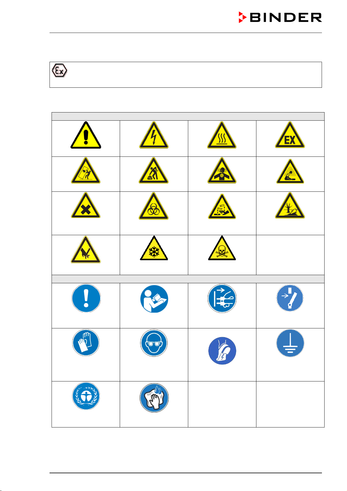
1.3.4 Explosion protection symbol .....................................................................................................8
1.3.5 Pictograms in this manual.........................................................................................................8
1.4 Localization / position of safety labels on the device ..........................................................................9
1.5 Type plates and classifications .........................................................................................................10
1.5.1 Type plate of the entire device VAP 5 ....................................................................................10
1.5.2 Type plate of the electric motor ..............................................................................................12
1.5.3 Type plate of the mechanical pump unit .................................................................................12
1.5.4 Classification on the cable gland ............................................................................................12
1.6 Ex classification of the device and immediate surroundings ............................................................13
1.6.1 Classification of the assembly “VAP 5 vacuum pump” ...........................................................13
1.6.2 Parts of the assembly “VAP 5 vacuum pump”........................................................................14
2. SAFETY................................................................................................................ 15
2.1 Personnel Qualification .....................................................................................................................15
2.2 Intended use .....................................................................................................................................17
2.3 Foreseeable Misuse..........................................................................................................................20
2.4 Residual Risks ..................................................................................................................................21
2.5 Operating instructions .......................................................................................................................22
2.6 Safety regulations .............................................................................................................................22
2.6.1 General information ................................................................................................................22
2.6.2 Safety instructions on installation ...........................................................................................23
2.6.2.1 Measures against overheating ..................................................................................................23
2.6.2.2 No installation in potentially explosive areas of Zone 1 or 0 .....................................................23
2.6.2.3 Technical ventilation (extraction ................................................................................................24
2.6.2.4 Equipotential bonding according to the grounding concept ......................................................25
2.6.2.5 Accessibility to the disconnection from the power supply .........................................................25
2.6.3 Safety instructions on operating the vacuum pump................................................................26
2.6.3.1 Measures against hazards caused by voltage ..........................................................................26
2.6.3.2 Measures against hazards caused by hot surfaces ..................................................................26
2.6.3.3 Measures against hazards from cold surfaces..........................................................................27
2.6.3.4Observe the maximum gas suction temperature ......................................................................27
2.6.3.5 Measures against condensation by pumping vapors ................................................................28
2.6.3.6 Ventilation precautions ..............................................................................................................28
2.6.4 Safety instructions on inert gas supply ...................................................................................29
2.6.5 Safety instructions on the aspirated media.............................................................................29
2.7 Operator responsibility, documentation, and measures ...................................................................30
2.7.1 Risk assessment / explosion protection document.................................................................30
2.7.2 Employee training and protocols ............................................................................................31
2.7.3 Operating instructions issued by the operator ........................................................................31
2.7.4 Personal protective equipment ...............................................................................................32
2.7.5 Standard Operating Procedures (SOP) ..................................................................................32
2.7.6 Testing and maintenance .......................................................................................................32
2.7.7 Operation log ..........................................................................................................................32
3. DEVICE DESCRIPTION ....................................................................................... 33
3.1 Device overview ................................................................................................................................33
3.2 Description and equipment ...............................................................................................................35
3.3 Manufacturer's safety plan: Protective measures and equipment ....................................................36

VAP 5 02/2022 Page 3/94
3.4 Area classification, information for the zone classification................................................................38
3.4.1 Area classification inside the VAP 5 vacuum pump ...............................................................38
3.4.2 Area classification in the surroundings of the VAP 5 vacuum pump ......................................38
3.4.3 Area classification in the surroundings of the VAP 5 vacuum pump when setting it up in the
pump module (optional) ..........................................................................................................39
4. COMPLETENESS OF DELIVERY, TRANSPORTATION, STORAGE, AND
INSTALLATION.................................................................................................... 40
4.1 Scope of delivery...............................................................................................................................40
4.2 Unpacking, and checking the equipment ..........................................................................................40
4.3 Guidelines for safe transportation .....................................................................................................41
4.4 Storage..............................................................................................................................................42
5. LOCATION OF INSTALLATION AND AMBIENT CONDITIONS......................... 42
5.1 General requirements for installation ................................................................................................42
5.2 Extraction (technical ventilation) .......................................................................................................42
5.3 Information on equipotential bonding ................................................................................................43
5.4 Ambient conditions ............................................................................................................................43
5.5 Permissible areas / zones in the installation area.............................................................................43
5.6 Accessibility of the main power switch / emergency stop .................................................................44
5.7 Fire extinguisher................................................................................................................................44
5.8 Lightning protection device ...............................................................................................................45
6. INSTALLATION AND CONNECTIONS ............................................................... 45
6.1 Installation in the pump module (optional) ........................................................................................45
6.2 Vacuum connection...........................................................................................................................45
6.3 Coolant connection ...........................................................................................................................47
6.4 Inert gas connections (optional) ........................................................................................................47
6.4.1 Inert gas connections for purging the drive chamber .............................................................48
6.4.2 Gas ballast inert gas connection.............................................................................................50
6.5 Achieving equipotential bonding / grounding concept ......................................................................51
6.5.1 Equipotential bonding of the components within the pump (delivery condition).....................51
6.5.2 Connection to the equipotential bonding of the system (by the customer).............................52
6.6 Electrical connection .........................................................................................................................54
7. EXPLOSION SAFETY TESTS ............................................................................. 55
7.1 Scope of the functional test...............................................................................................................55
7.2 Explosion protection plan ..................................................................................................................56
7.3 Objective of testing............................................................................................................................56
7.4 Testing before initial commissioning .................................................................................................56
7.5 Inspection after changes requiring review ........................................................................................57
7.6 Recurring tests for the explosive safety of the system .....................................................................57
8. COMMISSIONING ................................................................................................ 58
8.1 Requirements for safe commissioning..............................................................................................58
8.2 Tests / inspections ............................................................................................................................58
8.3 Turning on and off, emergency stop .................................................................................................59
9. OPERATION......................................................................................................... 60
9.1 Daily inspection .................................................................................................................................60
9.2 Removing and emptying the condensate catchpot ...........................................................................60
10. CLEANING AND DECONTAMINATION .............................................................. 62
10.1 Cleaning ............................................................................................................................................63
10.2 Decontamination / chemical disinfection...........................................................................................64
10.2.1 Decontamination of the external surfaces of the pump and the glass attachments...............64
10.2.2 Pump suction chamber decontamination................................................................................65

VAP 5 02/2022 Page 4/94
11. MAINTENANCE AND SERVICE, TROUBLESHOOTING, MAINTENANCE BY
THE OPERATOR, REPAIR, TESTING ................................................................ 66
11.1 General information, personnel qualifications...................................................................................66
11.2 Safety instructions.............................................................................................................................67
11.3 Regular inspection, maintenance intervals .......................................................................................68
11.3.1 Daily inspection by the operator .............................................................................................68
11.3.2 Regular inspection ..................................................................................................................68
11.3.3 Maintenance intervals .............................................................................................................69
11.4 Maintenance by the operator: Replacing of the form diaphragms....................................................69
11.4.1 Removing the pump unit from the housing .............................................................................70
11.4.2 Removing the equipotential bonding cable.............................................................................72
11.4.3 Replacing the service kit (form diaphragm, valves and o rings) .............................................72
11.4.4 Reinserting the pump unit into the housing ............................................................................74
11.4.5 Function test ...........................................................................................................................75
11.5 Simple troubleshooting......................................................................................................................75
11.6 BINDER Service contact data ...........................................................................................................77
11.7 Sending a device back to BINDER GmbH........................................................................................77
12. DISPOSAL............................................................................................................ 77
12.1 Disposal of the transport packing......................................................................................................77
12.2 Decommissioning..............................................................................................................................78
12.3 Disposal of the device in the Federal Republic of Germany.............................................................78
12.4 Disposal of the device in the member states of the EU except for the Federal Republic of Germany
..........................................................................................................................................................79
12.5 Disposal of the device in non-member states of the EU...................................................................80
13. TECHNICAL DESCRIPTION................................................................................ 80
13.1 Connections ......................................................................................................................................80
13.2 VAP 5 Technical data........................................................................................................................81
13.3 Circuit of the pump heads .................................................................................................................81
13.4 Materials of pump parts in contact with the medium.........................................................................82
13.5 Accessories and spare parts.............................................................................................................82
13.6 Diagrams of suction pressure / suction capacity ..............................................................................83
13.7 Dimensions........................................................................................................................................83
14. CERTIFICATES AND DECLARATIONS OF CONFORMITY............................... 84
14.1 EU Declaration of conformity ............................................................................................................84
15. DAMAGE REPORT .............................................................................................. 87
16. CONTAMINATION CLEARANCE CERTIFICATE ............................................... 89
16.1 For devices located outside the USA and Canada ...........................................................................89
16.2 For devices in the USA and Canada.................................................................................................92

VAP 5 02/2022 Page 5/94
Dear customer,
For the correct operation of the vacuum pump, it is important that you read this operating manual completely
and carefully and observe all instructions as indicated. Failure to read, understand and follow the
instructions may result in personal injury. It can also lead to damage to the device and/or poor equipment
performance..
1. Operating manual and classification
1.1 Operating manual
This operating manual is part of the components of delivery. Always keep it handy for reference in the
vicinity of the device. If selling the device, hand over the operating manual to the purchaser. This product
must not be distributed without the operating manual.
To avoid injuries and property damage observe the safety instructions of the operating manual. Failure to
follow instructions and safety precautions can lead to significant risks and to the loss of explosion protection.
Users/personnel must read and understand these operating instruction in full prior to starting work.
DANGER
Explosion hazard due to failure to observe the instructions and safety precautions.
Serious injuries and device damage. Risk of death.
Observe the safety instructions in this Operating Manual.
Follow the operating procedures in this Operating Manual.
Carefully read the complete operating instructions of the device prior to installing and
using the device.
Keep the operating manual for future reference.
Make sure that all persons who use the device and its associated work equipment have
read and understood the Operating Manual.
This Operating Manual is supplemented and updated as needed. Always use the most recent version of
the Operating Manual. When in doubt, call the BINDER Service Hotline for information on the up-to-
dateness and validity of this Operating Manual.

VAP 5 02/2022 Page 6/94
1.2 Legal considerations
This operating manual is for informational purposes only. It contains information for correct and safe
installing, start-up, operation, decommissioning, cleaning and maintenance of the product. The content of
this operating manual takes into account the applicable regulatory requirements and the latest technology.
The operator is responsible for ensuring proper use of vacuum apparatus / vacuum systems. The device
may only be used if it is in perfect technical condition.
Understanding and observing the instructions in this operating manual are prerequisites for hazard-free
use and safety during operation and maintenance. Images are to provide basic understanding. They may
deviate from the actual version of the device. The actual scope of delivery can, due to optional or special
design, or due to recent technical changes, deviate from the information and illustrations in these
instructions this operating manual. In no event shall BINDER be held liable for any damages, direct or
incidental arising out of or related to the use of this manual.
This operating manual cannot cover all conceivable applications. If you would like additional information,
or if special problems arise that are not sufficiently addressed in this manual, please ask your dealer or
contact us directly, e.g. by phone at the number located on page one of this manual.
Furthermore, we emphasize that the contents of this operating manual are not part of an earlier or existing
agreement, description, or legal relationship, nor do they modify such a relationship. All obligations on the
part of BINDER derive from the respective purchase contract, which also contains the entire and exclusively
valid statement of warranty administration and the general terms and conditions, as well as the legal
regulations valid at the time the contract is concluded. The statements in this manual neither augment nor
restrict the contractual warranty provisions.
Furthermore, relevant national and international regulations on occupational safety apply. The operator
must know, comply with, and implement these requirements. In particular, this includes the provisions of
ATEX Operational Directive 1999/92/EC (“ATEX 137”) (implemented for Germany in the Industrial Safety
Regulation (BetrSichV) and the Ordinance on Hazardous Substances (GefStoffV)). The operator is
responsible for choosing suitable work equipment for the areas classified as explosion hazards and for
installing and operating equipment in accordance with respective requirements.
Limitation of liability
BINDER GmbH is not liable for any damage arising from the following causes:
•Non-observance of Instruction Manual
•Improper use
•Improper installation, setup, maintenance, repair
•Inspections not being performed (testing before initial commissioning, recurring tests, testing before
recommissioning
•Negligence or willful intent
•Incorrect response to malfunctions
•Assignment of improperly or insufficiently trained personnel
•Technical changes and modifications made by the operator and not approved by the manufacturer
•Use of non-approved accessories and replacement parts
We reserve the right to technical changes as part of improvements to operating characteristics and further
development.
Have repairs performed only by experts authorized by BINDER. Repaired devices must comply with the
quality standard specified by BINDER. In particular, carry out an inspection before recommissioning after
maintenance or repairs. These can only be performed by the manufacturer or specially trained personnel
(in Germany: Qualified Persons per BetrSichVO).

VAP 5 02/2022 Page 7/94
1.3 Structure of the safety and warning notices
In this operating manual, the following safety definitions and symbols indicate dangerous situations
following the harmonization of ISO 3864-2 and ANSI Z535.6.
1.3.1 Warning levels
Depending on the probability of serious consequences, potential dangers are identified with a signal word,
the corresponding safety color, and if appropriate, the safety alert symbol.
DANGER
Indicates an imminently hazardous situation that, if not avoided, will result in death or serious
(irreversible) injury.
WARNING
Indicates a potentially hazardous situation which, if not avoided, could result in death or serious
(irreversible) injury.
CAUTION
Indicates a potentially hazardous situation which, if not avoided, may result in moderate or minor
(reversible) injury.
NOTICE
Indicates a potentially hazardous situation, which, if not avoided, may result in damage to the product
and/or its functions or to property in its proximity.
1.3.2 Representation of safety and warning notices
Pictogram WARNING LEVEL
Type / cause of hazard.
Possible consequences.
∅Instruction how to avoid the hazard: prohibition
Instruction how to avoid the hazard: mandatory action
Observe all other notes and information not necessarily emphasized in the same way, in order to avoid
disruptions that could result in direct or indirect injury or property damage.
1.3.3 Safety alert symbol
Use of the safety alert symbol indicates a risk of injury
Observe all measures that are marked with the safety alert symbol in order to avoid death or
injury.

VAP 5 02/2022 Page 8/94
1.3.4 Explosion protection symbol
Use of the explosion protection symbol warns against explosion hazards.
Observe all measures in this operating manual to avoid the formation of explosive atmosphere
as well as explosions.
1.3.5 Pictograms in this manual
Warning signs
Danger of injury
Electrical hazard
Hot surface
Explosive atmosphere
Stability hazard
Lifting hazard
Inhalation hazard
Suffocation hazard
Harmful substances
Biohazard
Risk of corrosion and /
or chemical burns
Pollution Hazard
Cutting injuries
Low temperature
warning
Toxic substances
warning
Mandatory action signs
Mandatory regulation
Read operating
instructions
Disconnect the power
plug
Release before
maintenance or repairs
Wear protective gloves
Wear eye protectors
Wear ESD shoes
(antistatic shoes)
Ground before use
Environment protection
Wipe with damp cloth
only

VAP 5 02/2022 Page 9/94
Prohibition signs
Prohibited
Do NOT touch
Do NOT spray with
water
Information to be observed in order to ensure optimum function of the product.
1.4 Localization / position of safety labels on the device
The following labels are located on the pump housing:
Safety labels (warning signs)
Hot surface
Figure 1: Position of the safety labels on the device
Keep safety labels complete and legible.
Replace safety labels that are no longer legible. Contact BINDER service for these replacements.

VAP 5 02/2022 Page 10/94
1.5 Type plates and classifications
There are three type plates / four classification labels on the device in the following positions:
(A)
(B)
(C)
Figure 2: Type plate positions
(A) Entire device (assembly)
(B) Pump unit
(C) Motor
1.5.1 Type plate of the entire device VAP 5
230V 115V
Figure 3: Type plate of the entire device VAP 5 (assembly)

VAP 5 02/2022 Page 11/94
Indications of the type plate of the entire device VAP 5
Indication
Information
BINDER
Manufacturer: BINDER GmbH
Vacuum pump
Device name: Vacuum pump
VAP 5
Model designation
Serial-No.
Serial no
II 2/3/- G IIB T4 Gb/Gc/- X
Ex classification according to ATEX Directive 2014/34/EU
P < 2 mbar
Final pressure
S 3,9 m3/h
S 4,3 m
3
/h
Suction capacity
(230V model: 3,9 m3/h; 115 V model: 4,3 m3/h)
1,3 A
3,1 A
Rated current
(230V-Modell: 1,3 A; 115 V-Modell: 3,1 A)
230 V 50 Hz
115 V 60 Hz
Nominal voltage +/- 10% at the indicated power frequency
IP protection
IP55
IP type of protection acc. to standard EN 60529
Art. No.
5013-0220
5013-0221
Art. No. of the device
Built
01/2022
Year and month of construction of the device (example)
Serial No.
202299
Serial no. of the device (example)
Symbols on the type plate
Symbol Valid for Information
All models CE conformity marking
All models
Electrical and electronic equipment manufactured / placed on the
market in the EU after 13 August 2005 and to be disposed of in a
separate collection according to Directive 2012/19/EU on waste
electrical and electronic equipment (WEEE).
All models Explosion protection symbol. Ex classification acc. to ATEX
Directive 2014/34/EU
Not for UL models
The device is certified according to Customs Union Technical
Regulation (CU TR) for the Eurasian Economic Union (Russia,
Belarus, Armenia, Kazakhstan Kyrgyzstan).

VAP 5 02/2022 Page 12/94
1.5.2 Type plate of the electric motor
230V 115V
Figure 4: Type plate of the electric motor
1.5.3 Type plate of the mechanical pump unit
Figure 5: Type plate of the mechanical pump unit
1.5.4 Classification on the cable gland
Figure 6: Cable gland with Ex classification

VAP 5 02/2022 Page 13/94
1.6 Ex classification of the device and immediate surroundings
1.6.1 Classification of the assembly “VAP 5 vacuum pump”
The designations “device” and “vacuum pump” in this operating manual describe the entire
assembly of the VAP 5 vacuum pump, consisting of the integrated pump unit, electric motor,
attachments such as emission condenser, separator and condensate catchpot, connection
cable, power plug, housing, and various other parts.
The VAP 5 vacuum pump is an assembly in the sense of ATEX Directive 2014/34/EU with the following Ex
classification:
II 2/3/- G IIB T4 Gb/Gc/- X in accordance with DIN IEC 60079-46.
X: The special conditions are included in the documentation of this whole assembly group
Explanation:
II Use of the device above ground
2 Equipment category 2 per ATEX Directive 2014/34/EU
Suitability for areas in which explosive atmospheres may occur occasionally.
Interior of the pump unit (fluid pumping area), tubing / line to the vacuum drying oven, outside
area of the pump unit (drive chamber) with inert gas purging
3 Equipment category 3 per ATEX Directive 2014/34/EU
Suitability for areas in which explosive atmospheres may occur, on a rare and temporary
basis:
The entire device, with the exception of the device power plug, is designed in Device category
3 in relation to the environment
Area at the installation site of the vacuum pump, interior of the optional pump module, outside
area of the pump unit (drive chamber) without inert gas purging.
- No equipment category per ATEX Directive 2014/34/EU
Device power plug (unprotected device area).
The device power plug is unprotected. The electrical connection must therefore be
established outside a zone.
See images of the areas in chap. 3.4.
G Substance group G per ATEX Directive 2014/34/EU
Gas: Do not introduce combustible dust into the device or allow combustible dusts to be
present in the vicinity of the device.
IIB Equipment subgroup IIB
Substances falling under Gas group / Explosion group IIA or IIB are permitted.
Substances falling under Gas group / Explosion group IIC are not permitted.
T4 Temperature class of the interior: T3 acc. to IEC 60079-0
Materials of temperature classes T4, T5, and T6 are not permitted. Only materials whose
auto-ignition temperature exceeds 200 °C / 392 °F may be aspirated.
Gb Equipment protection level (EPL) Gb acc. to EN IEC 60079-0 / EN ISO 80079-36
Suitability for areas in which explosive atmospheres may occur occasionally.
Interior of the pump unit (fluid pumping area), tubing / line to the vacuum drying oven, outside
area of the pump unit (drive chamber) with inert gas purging
Gc Equipment protection level (EPL) Gc acc. to EN IEC 60079-0 / EN ISO 80079-36
Suitability for areas in which explosive atmospheres may occur on a rare and temporary basis
(fault):
Outside area of the pump unit (drive chamber) without inert gas purging

VAP 5 02/2022 Page 14/94
- No equipment protection level (EPL) acc. to EN IEC 60079-0 / EN ISO 80079-36
Device power plug (unprotected device area)
X Specific operating conditions:
•Technical ventilation required during operation and when emptying the condensate catchpot
(chap. 5.2)
•Operation only allowed with equipotential bonding measures between parts of the pump and
with the system / installation surface (chap. 5.3)
•The pneumatic installation must prevent any backflow of fluid after shutting down the device
•Electrostatic charges must be prevented. Do not clean with dry cloths - Use only humid
cloths to wipe the device. The personal protective equipment (PPE) of the operating
personnel must be implemented ESD protected, i.e. against electrostatic discharge. No
processes that generate electrostatic charge, are permitted in the installation area of the
device.
•Only suitable gaseous media may be pumped. The device must be used in accordance with
its intended use (chap. 2.2)
•It must not be operated without its attachments.
•Regular inspections and maintenance work must be carried out
•Ambient temperature during operation: +18 °C up to +32 °C (permissible temperature
range Ta outside)
The operator is responsible for ensuring that the specific conditions of use are complied with
and that the device is used in accordance with its classification labelling.
1.6.2 Parts of the assembly “VAP 5 vacuum pump”
The “VAP 5 vacuum pump” assembly includes the following parts in the sense of the ATEX directive
2014/34/EU:
Component with a classification Classification
Mechanical pump
Non-electrical device, Ignition protection Ex h II 2/3 G Ex h IIB T4 Gb/Gc X
+10 °C ≤ Ta ≤ +40 °C
Interior of the pump unit (fluid pumping area), outside area of
the pump unit (drive chamber) with inert gas purging:
•Equipment category 2 per ATEX Directive 2014/34/EU
•Equipment protection level (EPL) Gb acc. to EN IEC 60079-
0 / EN ISO 80079-36
•Suitability for areas in which explosive atmospheres may
occur occasionally.
II 2G Ex h IIB T4 Gb X
Outside area of the pump unit (drive chamber) without inert
gas purging:
•Equipment category 3 per ATEX Directive 2014/34/EU
•Equipment protection level (EPL) Gc acc. to EN IEC 60079-
0 / EN ISO 80079-36
•Suitability for areas in which explosive atmospheres may
occur on a rare and temporary basis (fault)
II 3G Ex h IIB T4 Gc X

VAP 5 02/2022 Page 15/94
Component with a classification Classification
Electric motor
Electric device
•Ignition protection: Pressure-resistant casing “d” per EN IEC
60079-1, Equipment protection level: high protection “db”,
suitable for placement in Zone 1 or 2
•Equipment category 2 per ATEX Directive 2014/34/EU
•Equipment protection level (EPL) Gb acc. to EN IEC 60079-
0 / EN ISO 80079-36
•Suitability for areas in which explosive atmospheres may
occur occasionally.
II 2 G Ex db IIB T4 Gb -20 °C ≤
Ta ≤ +40 °C
Cable gland
Electric device
•Equipment category 2 per ATEX Directive 2014/34/EU
•Equipment protection level (EPL) Gb acc. to EN IEC 60079-
0 / EN ISO 80079-36
•Suitability for areas in which explosive atmospheres may
occur occasionally.
•Ignition protection: Pressure-resistant casing “d” per EN IEC
60079-1, Equipment protection level: high protection “db”,
suitable for placement in Zone 1 or 2
II 2G 1D Ex db IIC Gb […]
CMP UK 20S A2F M20 CML
18ATEX1321X
II 2G 1D CE 2776
IECEx CML 18 0179X
Ex db IIC Gb / Ex eb IIC Gb / Ex nR
IIC Gc / Ex ta IIIC Da
CSA E X d IIC, Ex e II Ex nR II E??
Type 4X -60° +130°C IP66 / 67 / 68
Other parts
Power supply connector
No equipment category per ATEX Directive 2014/34/EU, No classification, unprotected
Connection outside of a zone required
Emission condenser
Coupling
Non-electrical device
Cable with a length of 3m acc. to DIN EN 60079-14
Glass attachments: condensate catchpot and separator
2. Safety
2.1 Personnel Qualification
The operator must ensure that the personnel are properly trained and that all necessary protective
measures are complied with.
GEFAHR
Hazards during activities by untrained personnel.
Serious injuries and device damage. Risk of death.
Follow the instructions on personnel qualification in this operating manual.

VAP 5 02/2022 Page 16/94
Overview of responsibilities
The operator (responsible representative for processes) is responsible for risk assessment, explosion
protection concept, zone classification, instruction of employees, creation of operating and work
instructions, provision of protective equipment, responsibility for tests and maintenance, etc. (see chap.
2.7).
The device is to be used by laboratory personnel who have been trained for this purpose and are familiar
with all safety measures for working with equipment in accordance with ATEX Directive 2014/37/EU, are
aware of and bear in mind the particular hazards, and have understood the functionalities and operating
instructions for the device. Follow the country-specific regulations on the minimum age of laboratory
personnel (in Germany: 14 years).
Installation, testing, commissioning, fault analysis, operator maintenance work (membrane
replacement) is to be carried out by qualified personnel with additional skills in explosion protection (ATEX),
who are familiar with the assembly, commissioning and operation of the device. Qualified personnel are
persons whose professional education, knowledge, experience and knowledge of relevant standards allow
them to assess, carry out, and identify any potential hazards in the work assigned to them. This includes
persons with professional qualifications, such as mechanics, electricians and laboratory managers. They
must also have been trained and instructed, and be authorized, to work on the device. This includes basic
knowledge of explosion protection (ATEX training), instruction of the operator based on the risk assessment
(chap. 2.7.2) and knowledge of the operator’s operating instructions.
Repairs may only be carried out by the manufacturer or service providers authorized by the manufacturer.
Tabular overview of responsibilities for working on the device
Action to take Trained
laboratory
personnel
Qualified personnel
with additional skills
in explosion
protection
Manufacturer or
service provider
authorized by the
manufacturer
Transport, storage, setting up x x x
Installation:
Vacuum connection
Refrigerant connection
Inert gas connection
Achieving equipotential
bonding
Electrical connection
x x
Commissioning x x x
Operation x x x
Removing and emptying the
condensate catchpots x x x
Daily inspection x x x
Regular inspection x x x
Testing before commissioning x x
Testing after maintenance /
repair x x
Cleaning x x x
Decontamination of the
external surfaces of the pump
and the glass attachments
x x x
Decontamination after use of
hazardous substances X (depending on the
application) X

VAP 5 02/2022 Page 17/94
Action to take Trained
laboratory
personnel
Qualified personnel
with additional skills
in explosion
protection
Manufacturer or
service provider
authorized by the
manufacturer
Maintenance work to be
carried out by operator
(membrane replacement)
x x
Analyze malfunctions x x x
Eliminate malfunctions x x x
Damage report, Contamination
clearance certificate x x
Disposal x x
2.2 Intended use
Following the instructions in this operating manual and conducting regular maintenance work
(chap. 11) are part of the intended use.
Any use of the products that does not comply with the requirements specified in this Operating Manual shall
be considered improper use.
All applications must be within the specification (see Technical data, chap. 13.1 and indications on the type
plate, chap. 1.5).
Other applications than those described in this chapter are not approved.
Use of the device that does NOT correspond to its intended use is considered improper use.
DANGER
Risk of explosion due to improper use of the device
Serious injury or death from burns and / or explosion pressure.
Ensure the device is operated in accordance with the intended use.
Only operate the device according to its EX classification.
Follow the relevant statutory regulations.
Use
The VAP 5 vacuum pump is suitable for conveying gaseous media.
The diaphragm pumps are intended for:
•Creating vacuum
•Use in physical and chemical laboratories in trade or industry
Use for vacuum filtration, vacuum distillation and vacuum drying as well as other applications in vacuum
technology
Area of application
The VAP 5 vacuum pump is used to extract gaseous media, in particular from the BINDER VDL vacuum
drying ovens. It is suitable for pumping flammable solvents up to an ignition temperature of 200 °C as well
as non-flammable solvents.
The solvent contained in the aspirated medium must not be able to form an explosive mixture with air under
normal conditions. The ignition of an explosive atmosphere is prevented by various safety measures.

VAP 5 02/2022 Page 18/94
The pump is suitable for laboratory and industrial use in rough vacuum workspaces and is designed for
continuous operation.
The device must be connected in accordance with the statutory requirements and operated in compliance
with the technical data and specifications on the type plate.
•extracting, conveying and compressing harmless gases and vapors.
•extracting, conveying and compressing of explosive atmospheres consisting of air and combustible
gases, vapors and mists in any mixing ratio according to the EX classification of the device.
Requirements for the aspirated atmosphere
Only substances with an auto-ignition temperature that is higher than 200 °C / 392 °F may be aspirated.
The devices are not suitable to aspirate substances with an auto-ignition temperature below 200 °C / 392
°F. Substances falling under Gas group / Explosion group IIC are not permitted (e.g. carbon disulfide,
acetylene, hydrogen. Substances falling under groups II A and II B may be aspirated.
The temperature class of the interior according to IEC 60079-0 is T3. The auto-ignition temperature is
determined from the safety specifications of the solvent used. In the case of solvent mixtures, the solvent
with the lowest auto-ignition temperature as this is critical.
According to IEC 60079-0 the VAP 5 vacuum pump is NOT intended for the temperature classes T4, T5
and T6. Insert only substances with an auto-ignition temperature that is higher than 200 °C / 392 °F.
The description of explosion protection on the type plate of the assembly determines the classification
The VAP 5 vacuum pump is NOT suitable for substances, which tend towards exothermal decomposition,
or for materials that come under the legal definition of explosives. Such substances must not be aspirated.
Dangerous chemical reactions must not occur. Exothermal reactions must definitely be excluded.
Familiarize yourself with the physical and chemical properties of the aspirated material, as well as the
contained moisture constituent and its behavior with changes in pressure. Familiarize yourself with any
potential health risks caused by aspirated material, the contained moisture constituent or by reaction
products. Take adequate measures to exclude such risks prior to putting the device into operation.
Aspirated gases and vapors shall not contain any corrosive ingredients that may damage the machine
components. Such ingredients include in particular acids and halides. Any corrosive damage caused by
such ingredients is excluded from liability by BINDER GmbH.
The VAP 5 vacuum pump is NOT suitable for use in conjunction with explosive dust atmospheres or hybrid
mixtures. Combustible dust are generally not permitted
The temperature of the aspirated gases and vapors must not exceed the permissible gas inlet temperature
of max. 40 °C / 104°F when entering the pump.
The pump is not suitable for aspirating liquids.
DANGER
Explosion or implosion hazard and danger of poisoning through the aspiration of
unsuitable gases and vapors.
Poisoning. Serious injury or death from burns and / or explosion pressure.
∅Do NOT aspirate any substance with an auto-ignition temperature below 200 °C /
392 °F.
∅Do NOT aspirate any combustible dust.
∅Do NOT aspirate any substance, which tend to exothermic decomposition.
∅Do NOT aspirate any substance, which fall under the explosives law
∅With a set-point temperature above 40 °C / 104 °F, take appropriate measures to cool
down the aspirated vapor before its entry to the vacuum pump

VAP 5 02/2022 Page 19/94
The aspiration of gases and vapors must NOT result in the release of toxic gases. Contamination of the
device by toxic, infectious or radioactive substances must be prevented
WARNING
Danger of intoxication and infection through contamination of the device with toxic,
infectious or radioactive substances.
Damages to health.
Make sure that NO toxic, infectious or radioactive substances can be aspirated.
Take suitable protective measures when introducing and removing accidentally
aspirated toxic, infectious or radioactive material.
Solid particles in the aspirated medium impair the pumping action and can damage the pump.
NOTICE
Danger of mechanical damage and malfunctions due to the suction of solid
particles.
Damage to the device.
Prevent solid particles from entering the pump.
In case of foreseeable use of the device there is no risk for the user through the integration of the device
into systems or by special environmental or operating conditions in the sense of EN 61010-1:2010. For this,
the intended use of the device and all its connections must be observed.
Medical devices
The devices are not classified as medical devices as defined by Regulation (EU) 2017/745.
Personnel Requirements
Only trained personnel with knowledge of the Operating Manual can set up and install the device, start it
up, operate, clean, and take it out of operation. Service and repairs call for further technical requirements
(e.g. electrical know-how),.
Only trained personnel with knowledge of explosion protection and knowledge of the Operating Manual can
set up and install the device, start it up, operate, clean, and take it out of operation. Service and repairs call
for further technical requirements (e.g. electrical know-how). Follow the requirements for PPE (ESD
protection), see chap. 2.1.
Installation site requirements
The devices are designed for setting up inside a building (indoor use).
Provide active extraction (technical ventilation according to country-specific regulations – TRBS 2152 Part
2 for Germany) on the installation site. It must cover the entire installation area of the vacuum pump. Suction
must be active during the entire operation of the device and when handling the condensate catchpot of the
pump. Suction must be conducted into an explosion-proof area.
The requirements described in the Operating Manual for installation site and ambient conditions (chap. 5)
must be met. In particular, the operator’s protective measures with regard to equipotential bonding and
zone classification must be observed.
The device is not intended for installation in a Zone 0 or 1. The device is not to be installed and operated
in areas that occasionally or frequently / permanently have potential explosive atmospheres. The EX
labelling must be observed, see chap. 1.6.
The device plug (power plug) is not explosion-proof. The electrical connection must therefore be located
outside a zone.

VAP 5 02/2022 Page 20/94
Requirements for the operator
Based on his risk assessment, the operator must draw up an explosion protection plan, classify zones and
define and implement tests and protective measures. Please refer to chap. 2.7.
Connected devices must be operated within the scope of their specification and in compliance with their
operating instructions
Only spare parts and accessories approved by the manufacturer may be used
The device may only be operated in perfect technical condition and with complete documentation.
Applications that are contrary to the intended use must be prevented by the operator.
2.3 Foreseeable Misuse
Other applications than those described in chap. 2.1 are not approved. These are considered improper
use.
This expressly includes the following misuses (the list is not exhaustive), which pose risks despite the
inherently safe construction and existing technical safety equipment:
•Non-observance of the Operating Manual
•Non-observance of information and warnings on the device
•Installation, startup, operation, maintenance and repair by untrained, unqualified, insufficiently qualified,
or unauthorized personnel
•Unattended operation in critical applications
•Operating the device with tools or other prohibited objects.
•Suction of impermissible, liquid or particulate media, aspiration of materials excluded or not permitted
by this Operating Manual.
•Missed or delayed maintenance and testing
•Non-observance of traces of wear and tear
•Installation, testing, service or repair in the presence of solvents
•Manipulation of the device, such as improper attachments or modifications.
•Installation of replacement parts and use of accessories and operating resources not specified and
authorized by the manufacturer
•Installation, startup, operation, maintenance or repair of the device in absence of a risk assessment and
operating instructions from the operator
•Installation, startup, operation, maintenance or repair of the device with inadequate or non-existent
protective measures.
•Bypassing or changing protective systems, operation of the device without the designated protective
systems
•Non-observance of messages regarding cleaning and disinfection of the device.
•Wiping the device with a dry cloth, generating static charge
•Spilling water or cleaning agent on the device, water penetrating into the device during operation,
cleaning or maintenance.
•Cleaning activity while the device is turned on.
•Operation of the device with a damaged housing or damaged power cord
•Continued operation of the device during an obvious malfunction
•Insertion of objects, particularly metallic objects, in louvers or other openings or slots on the device
•Human error (e.g. insufficient experience, qualification, stress, exhaustion, laziness)
This manual suits for next models
2
Table of contents
Other Binder Water Pump manuals
Popular Water Pump manuals by other brands

SAB
SAB F101 Instructions for use

Alemite
Alemite 8430 Service guide

Senci
Senci SCWT-100 operation instruction

Victor Pumps
Victor Pumps C Series Instruction and maintenance manual

Interpump Group
Interpump Group Pratissoli WK Series Repair manual

meibes
meibes MK Series Technical information for installation and operation