Bindex BI-2 User manual

Updated 9 October 2019 U.S. law restricts this device to sale by or on the order of a physician.
© 2019 Bone Index Finland Ltd.
All Rights Reserved.
User Manual
Bindex® Standalone Software version 2.8
Bindex® model BI-2
0537

Updated 9 October 2019 U.S. law restricts this device to sale by or on the order of a physician.
Table of Contents
1. List of figures................................................................................................4
2. Warnings and precautions ..........................................................................8
3. Symbols and Abbreviations ......................................................................10
3.1. Abbreviations..................................................................................................................10
3.2. Symbols ..........................................................................................................................10
4. Indications for use ..................................................................................... 11
4.1. Intended use ....................................................................................................................11
5. Bindex BI-2 overview and technical specification ..................................13
6. Operating environment ............................................................................. 17
7. Setup ...........................................................................................................18
7.1. Unpacking Bindex ..........................................................................................................18
7.2. Software installation .......................................................................................................18
7.3. Device driver installation................................................................................................21
7.4. Software activation .........................................................................................................22
7.4.1. First time activation....................................................................................... 22
7.4.2. Ordering additional analyses ......................................................................... 24
7.4.3. Additional software ....................................................................................... 25
7.5. User Management Application (UMA)...........................................................................26
7.5.1. Password protection ...................................................................................... 27
7.5.2. Creating new operators.................................................................................. 28
7.5.3. Modifying operator details ............................................................................ 28
7.5.4. Deleting operators ......................................................................................... 29
7.5.5. Resetting the administrator password............................................................ 30
7.6. Bindex device setup ........................................................................................................32
8. Using Bindex ..............................................................................................33
8.1. Connecting and disconnecting the Bindex device ..........................................................33
8.2. Basics of Bindex Standalone Software ...........................................................................34
8.2.1. Logging in with password protection enabled............................................... 34
8.2.2. Logging in with password protection disabled.............................................. 35
8.2.3. Front page and functions ............................................................................... 35
8.2.3.2. Open case................................................................................................. 38
8.3. Patient information .........................................................................................................44
8.4. Patient positioning ..........................................................................................................47
8.5. Measurement site location ..............................................................................................48
8.6. Bindex quality verification .............................................................................................52
8.7. Measurement with Bindex ..............................................................................................53
8.8. Signal Acceptance Window ............................................................................................58
8.9. Interpretation of the Bindex results.................................................................................61
9. Cleaning, disinfecting and packing Bindex BI-2 ....................................64
10. Bindex service ............................................................................................66
11. Storing of Bindex .......................................................................................67
11.1. Disposal ..........................................................................................................................67
12. Contact information ..................................................................................67
13. Troubleshooting .........................................................................................68
13.1. Installing Bindex Standalone Software...........................................................................68
13.2. Using Bindex Standalone Software ................................................................................69
13.3. Measuring with Bindex...................................................................................................73
Software License Agreement ............................................................................. 74
Appendix: Guidance and manufacturer’s declaration - Electromagnetic
Compatibility ......................................................................................................75

Bindex® BI-2 User Manual
© Bone Index Finland Ltd.
All Rights Reserved.
3
Note: The content of this document is confidential, proprietary and copyrighted by Bone Index Finland Ltd.
It is provided for use by the customers and authorized representatives of Bone Index Finland Ltd.
Bindex® is a registered trademark of Bone Index Finland Ltd. Any third-party products mentioned within
this manual are registered and copyrighted with their respective companies.
The Quality Management System of Bone Index Finland Ltd. complies with the United States Food and
Drug Administration Code of Federal Regulations Title 21 Part 820 (Quality System Regulation), the
Quality Management Standard ISO 13485 and the products comply with the Medical Device Directive
MDD 93/42/EEC requirements.

Bindex® BI-2 User Manual
© Bone Index Finland Ltd.
All Rights Reserved.
4
1. List of figures
Figure 1: A Computed Tomography image of tibia shows the tubular structure of
the bone (black area). When measuring the tibia with Bindex, the ultrasound
echoes back from the front (1) and the back (2) surface of cortical bone layer.
These echoes need to be clearly distinguishable. Bindex will automatically accept
the echoes.
Figure 2: Bindex BI-2 device shown together with the BI-41 Measure.
Figure 3: The Bindex Measure is used for determination of standard
measurement location at the tibia.
Figure 4: Setting the installation directories. The paths may be changed if
needed.
Figure 5: The license agreements. Carefully read the terms before proceeding.
After accepting the licenses, continue with the installation by clicking on NEXT.
Figure 6: Starting the installation.
Figure 7: Installation completed successfully. Exit the installation program by
pressing NEXT.
Figure 8: Device driver installation.
Figure 9: When you run the software for the first time a dialog appears..
Figure 10: Before the software is activated a dialog showing your customer key
and asking for the activation key appears.
Figure 11: The software notification when the correct software activation file is
opened.
Figure 12: License and PPA window. You can create new order keys and add
ordered PPAs from this menu.
Figure 13: Only the Bindex administrator can login to the User Management
Application.
Figure 14: The administrator is required to change the password after the first
login.
Figure 15: User Management Application main window.
Figure 16: Creating a new operator account.
Figure 17: Modifying operator details. The administrator can change the Display
name or e.g. reset a forgotten password of an operator.
Figure 18: Confirmation for deleting an operator account.

Bindex® BI-2 User Manual
© Bone Index Finland Ltd.
All Rights Reserved.
5
Figure 19: The dialog for resetting the administrator password.
Figure 20: The Login window of Bindex Standalone Software, when password
protection is enabled.
Figure 21: At first login, the user is required to change the password.
Figure 22: The Login view, when password protection is disabled. Press the
LOGIN button to set the operator name and continue to the front page of the
program.
Figure 23: Front page of Bindex® software. You can always get back to this page
by pressing the HOME button in the upper right corner.
Figure 24: After 30 minutes of inactivity Bindex Standalone Software is locked.
The program can also be locked at any time by pressing the LOCK (symbol)
button.
Figure 25: The software asks a confirmation before starting a new case over an
existing case.
Figure 26: Open case view. By using the BACK button you will continue to front
page of the software.
Figure 27: Delete a patient or measurement from the database.
Figure 28: Change settings view. In this page you can change the program,
language, operator and company information settings and the default directory
for saving the PDF reports.
Figure 29: Changing the operator password. Enter the previous password once
and the new password twice, then click on CHANGE.
Figure 30: The Patient page. All information must be entered before you can
continue by using the NEXT button. By saving the patient info you can find the
info from OPEN CASE later
Figure 31: Software asks confirmation before writing over existing data.
Figure 32: You will be asked to fill the necessary patient information before
continuing to the measurement.
Figure 33: If enabled in settings, the FRAX questionnaire can be filled in after
the basic information of the patient has been entered.
Figure 34: Patient positioning on a bed. Remember to keep an ergonomic
position when you are measuring.
Figure 35: Locating and marking the knee joint. First you must locate the upper
head of the tibia or the knee joint.

Bindex® BI-2 User Manual
© Bone Index Finland Ltd.
All Rights Reserved.
6
Figure 36: Locating the distal head of tibia. The arrow head of the stick is located
on the medial malleolus. After this, check the number on the Bindex Measure at
the mark at the knee joint.
Figure 37: Locating the measurement location. The right measurement location
can be found at the same number on scale 3 (or C), e.g. number 12 in this picture.
Figure 38: The tibia typically has a plate-like cortical surface at this site. The
measurement should be made at the center of cortical bone plate.
Figure 39: Enter the measurement location number from the Bindex Measure in
the Location tab.
Figure 40: The transducer head should be freely in air when you press the
CALIBRATE button.
Figure 41: The CALIBRATE button. The button for calibration is located at the
upper right corner. Measurement cannot be started before a successful
calibration.
Figure 42: A failed calibration. Software notifies the user if the calibration was
not successful.
Figure 43: Conducting the measurement. First put the transducer next to bone
and then move it over the bone. Keep an eye on the ultrasound signal on the
signal window. When you see two echo spikes in the signal you are at the right
location.
Figure 44: The use of the BOOST button. Measurement signal before (left) and
after (right) boost effect.
Figure 45: A noisy signal. If you use too much amplification you may see a very
noisy signal. Now there are many strong echo spikes. An acceptable
measurement only includes two strong spikes.
Figure 46: Window for accepting or discarding the measured signals. In this
example the measurements are uniform and are therefore all accepted.
Figure 47: A signal deviating from the average. In this figure the bottom signal
deviates significantly from the average of all measurements and is therefore
suggested to be discarded by the software.
Figure 48: Excessive amplification. All signals shown in this figure should be
discarded because they show too much noise and multiple high peaks due to the
excessive use of the BOOST button.
Figure 49: Incorrectly positioned probe. The lower signals marked as red deviate

Bindex® BI-2 User Manual
© Bone Index Finland Ltd.
All Rights Reserved.
7
significantly from the average because the probe has been in a tilted position in
comparison to the measurement location. The amount of noise generated in the
signals is also high. The signal peaks accepted by the software have been marked
to the figure with dots.
Figure 50: The result page includes patient information, Density Index and
apparent cortical bone thickness values. In addition, the Density Index value is
also presented on a three-color scale (green, yellow and red).
Figure 51: Failed activation notifications.
Figure 52: Bindex device not connected before running the program after
activation.
Figure 53: Example of a general error message.
Figure 54: The information that should be sent to Bone Index Finland Ltd. after
receiving an unknown error message.
Figure 55: Error when changing software settings or at software startup.
Figure 56. User Manual not found.

Bindex® BI-2 User Manual
© Bone Index Finland Ltd.
All Rights Reserved.
8
2. Warnings and precautions
Before using Bindex, user must read and understand the following safety-related
information. The user shall adhere to warning in order to ensure a safe and reliable
performance of the system.
The Bindex system needs special precautions regarding EMC
and needs to be installed and put into service according to the
EMC information provided in Appendix: Guidance and
manufacturer’s declaration - Electromagnetic Compatibility.
Portable and mobile radio frequency (RF) communications
equipment can affect the Bindex BI-2 device.
Equipment used with Bindex measuring system must comply
with IEC 60601-1 (medical equipment), IEC 60950 (non-
medical equipment) or their general IEC/ISO variants.
Non-medical equipment (including the PC) should be located
outside the patient environment as described in IEC 60601-1.
If it is necessary for the non-IEC 60601 compliant equipment
to be located within the patient environment, that equipment
shall be powered by an internal battery, a medical safety
isolation transformer or connected to system ground via an
additional protective earth terminal.
WARNING: Use of this equipment adjacent to or stacked with
other equipment should be avoided because it could result in
improper operation. If such use is necessary, this equipment
and the other equipment should be observed to verify that they
are operating normally.
Do not make Bindex measurements on the surface of skin with
open sores. There is an inflammation risk.
Do not use the Bindex device on broken or irritated skin or in
case of a fractured bone at measurement location.
Do not use the Bindex device in case of implants, plates or
fixations at measurement location.
Do not use the Bindex device outdoors. See 6 Operating
environment.
Do not use the Bindex device near a heat source or an air
conditioner. This may cause condensation of moisture inside
the equipment.
Use only approved ultrasound coupling gel for measurements
with the Bindex device.
Bindex® BI-2 User Manual
© Bone Index Finland Ltd.
All Rights Reserved.
9
Do not apply ultrasound gel on the surface of the Bindex
transducer before calibration. See 8.6 Bindex quality
verification.
Always use the Bindex Measure for determination of the proper
measurement location. The location is standardized for this
measurement to produce reliable results.
If you drop or bump the device on hard surfaces, make quality
verification measurements. In case of any mechanical or
visible damage, please contact your local distributor or Bone
Index Finland Ltd. for service. Do not use a damaged device!
The Bindex device is not intended to be used in oxygen rich
environment.
The patient shall be informed not to touch the connectors of
the ME system (e.g. laptop connectors) during measurements.
Do not use a USB extension cord between the Bindex device
and the computer.
Caution: Federal law restricts this device to sale by or on the
order of a physician.
WARNING: Use of accessories, transducers and cables other
than those specified or provided by the manufacturer of this
equipment could result in increased electromagnetic emissions
or decreased electromagnetic immunity of this equipment and
result in improper operation.
WARNING: Portable RF communications equipment (including
peripherals such as antenna cables and external antennas)
should be used no closer than 30 cm (12 inches) to any part of
the Bindex device, including cables specified by the
manufacturer. Otherwise, degradation of the performance of
this equipment could result.

Bindex® BI-2 User Manual
© Bone Index Finland Ltd.
All Rights Reserved.
10
3. Symbols and Abbreviations
3.1. Abbreviations
US Ultrasound
DI Density Index
DXA Dual Energy X-ray Absorptiometry
BMD Bone Mineral Density
Cth. Cortical thickness
3.2. Symbols
Consulting accompanying documents before use is mandatory.
Device manufacturer contact information.
Type B applied part.
General warning.
Caution.
Operating Instructions.
Class II device, referring to electrical equipment in which
protection against electric shock does not rely on basic
insulation only, but in which additional safety precautions such
as double insulation or reinforced insulation are provided, there
being no provision for protective earthing or reliance upon
installation conditions
In this manual, software controls are indicated as follows: BUTTONS in capital
letters, Windows and Pages in bolded capital and small letters and Editable
fields in italic typeface.

Bindex® BI-2 User Manual
© Bone Index Finland Ltd.
All Rights Reserved.
11
4. Indications for use
Bindex measures apparent cortical bone thickness at the proximal tibia and can be
used in conjunction with other clinical risk factors or patient characteristics as an
aid to the physician in the diagnosis of osteoporosis and other medical conditions
leading to reduced bone strength and in the determination of fracture risk.
4.1. Intended use
Bindex measures apparent cortical bone thickness at the upper shaft of tibia (See
Figure 1) and reports the diagnostic parameter, Density Index (DI), an estimate of
hip Bone Mineral Density measured with gold standard Axial DXA. Thresholds
for osteoporosis for DI have been determined in comparison to DXA. The DI
reported by Bindex is used as an aid in osteoporosis diagnostics by applying pre-
determined thresholds. DI can help the clinician in estimation of fracture risk.
After the measurement, Bindex Software gives an estimation of the presence of
osteoporosis marked in the color bar: Green (Low Probability of Osteoporosis),
Yellow (Additional Investigations Needed) or Red area (High Probability of
Osteoporosis). A total of 90% of osteoporotic patients diagnosed by hip BMD are
in the yellow or red area (90% sensitivity) and 90% of non-osteoporotic patients
are in the green or yellow area (90% specificity). Statistically at least 80%
sensitivity and specificity for hip osteoporosis will be reached with 95%
confidence. Patient classification is based on thresholds (separating
red/yellow/green areas) published in a study by Karjalainen et al. “New method
for point-of-care osteoporosis screening and diagnostics” in Osteoporosis
International 2016.
Currently the use of Bindex DI thresholds is validated for Caucasian women at the
age between 50 to 90 years. Bindex measurement takes about one minute. Bindex
device should be operated by a physician or under supervision of physician by a
nurse, pharmacist or trained person with a suitable background education and
skills.

Bindex® BI-2 User Manual
© Bone Index Finland Ltd.
All Rights Reserved.
12
Figure 1: A Computed Tomography image of tibia shows the tubular structure of the bone (black
area). When measuring the tibia with Bindex, the ultrasound echoes back from the front (1) and
the back (2) surface of cortical bone layer. These echoes need to be clearly distinguishable. Bindex
will automatically accept the echoes.

Bindex® BI-2 User Manual
© Bone Index Finland Ltd.
All Rights Reserved.
13
5. Bindex BI-2 overview and technical specification
Device overview
The Bindex BI-2 device consists of the handpiece including the measurement
electronics and the USB cord (Figure 2). The device is connected to a free USB
port of a personal computer. In the device, an electrical pulse is sent to the
transducer which transforms the pulse into ultrasound waves that are transmitted
into the bone. The transducer collects the sound waves reflected from the bone and
transmits the signal via the electronics to the PC software for analysis.
Bindex - Software
Bindex utilizes software which is provided to customer on a USB drive or as a
downloadable installation package. The software can be installed on Windows
7/8/10 operating systems on a PC. The Bindex device is operated using the
software GUI (Graphical User Interface) which controls the pulser and collects the
measured signals. Signals are analyzed to calculate the diagnostic/screening
parameter DI. Results are saved in the Bindex database and can be exported in
PDF format or as a text file for easy transfer to e.g. a spreadsheet program.
Figure 2:
Bindex BI-2 device shown together with the BI-41 Measure.

Bindex® BI-2 User Manual
© Bone Index Finland Ltd.
All Rights Reserved.
14
Bindex - Measure
For determination of the standard location for Bindex measurement, device is
supplied with a custom stick measure (Figure 3). The Bindex Measure is always
used to determine the ultrasound measurement location at 1/3 length of the
proximal tibia.
Figure 3:
The Bindex Measure is used for determination of standard measurement location at
the tibia.

Bindex® BI-2 User Manual
© Bone Index Finland Ltd.
All Rights Reserved.
15
Specifications
Mechanics
Weight (incl. USB cord)
128g
Size (handpiece)
119 x 42 x 34mm
(length x width x height)
USB cord length
2.0 m
Electrical
Power supply
Powered from PC USB port, 5V
Environmental
Operating Temperature
+15...+40 ° C
Storage Temperature
+15...+40 ° C
Atmospheric Pressure
600hPa to 1060hPa (mbar)
Humidity
5…85%
Ultrasound
Transducer centre frequency
3.0 MHz
Transducer type
Focused
Mechanical Index
0.220
Thermal Index (TIBbs,ns)
0.011
Spatial-peak temporal-average
intensity (Ispta)
6.5 mW/cm2
Bindex and the connected PC are together considered a medical electrical system.
The computer power source must comply with the IEC 60950-1:2005 standard,
otherwise it is mandatory to connect the PC operated with Bindex to the mains
supply with a medical isolation transformer. An isolation transformer or an
additional protective earth connection from the computer is also required when the
computer does not comply with IEC 60601-1 and it is used within the patient
Safety standards compliance
Medical electrical equipment safety
IEC 60601-1 ed. 3.0
Ultrasound safety
IEC 60601-2-37 ed. 2.0 and IEC
62359 ed. 2.0
Bindex® BI-2 User Manual
© Bone Index Finland Ltd.
All Rights Reserved.
16
environment.
Bindex can also be used with an IEC 60950-1:2005 compliant laptop computer
operating on battery power. In this case, no additional precautions concerning
electrical safety are required.
The PC to which Bindex is connected needs to comply with
IEC 60950-1:2005 2.ed. or should be connected to power grid
through a medical isolation transformer.
A medical isolation transformer is not needed when the PC is
on battery use.

Bindex® BI-2 User Manual
© Bone Index Finland Ltd.
All Rights Reserved.
17
6. Operating environment
See section 5 for operating and storing conditions.
•The basic principle is that you may use Bindex in the same environment as your
computer.
•Bindex is intended to be operated indoors, in clinics, hospitals or domestic
environment (see Appendix: Guidance and manufacturer’s declaration -
Electromagnetic Compatibility for power supply requirements) by a licensed
practitioner.
•Bindex is not recommended to be used near active high frequency surgical
equipment or in an RF shielded room of an ME system for magnetic resonance
imaging, where the intensity of electromagnetic disturbances is high.
•Bindex is powered from the USB port of your computer. Please make sure that
your computer is connected to a power source (battery or a mains outlet).
•Do not use Bindex near heat source or air conditioner and do not expose device
to excessive moisture, above or under specified limits in section 5.
•Do not store your Bindex in a place where it exposes to sunlight.
•Measurements can be done while patient is either sitting or lying on a bed.
Computer hardware requirements
Operating System:
Windows 7, Windows 8 (8.1) or Windows 10
Processor:
2 GHz, 32-bit or 64-bit
Memory:
2 GB
Hard Disk Drive:
installation:
72 MB Bindex Standalone Software
353 MB LabVIEW Run-Time Engine 2012
109 MB Microsoft Access database engine 2010
2 MB device drivers
in use:
1.7 MB per patient
Screen Resolution:
1024x768
Other:
USB port
.NET framework v.4.0.30319 or newer (upgrade
with Windows Update, if necessary)

Bindex® BI-2 User Manual
© Bone Index Finland Ltd.
All Rights Reserved.
18
7. Setup
7.1. Unpacking Bindex
When you have received your Bindex BI-2 device package, remember to check
that you have all components/parts which are listed in the packing list. Also
remember to check that the packing list includes everything you have ordered. The
package includes at least a Bindex BI-2 device, a software installation disk, a User
manual in electronic form and one Bindex Measure.
7.2. Software installation
Installation of the Bindex Standalone Software should be done by a person with at
least basic knowledge and experience about the Windows OS and installing new
programs and hardware, e.g. a nurse with experience on the subject or an IT
support technician. Software can also be installed by a Bindex representative as
agreed.
PLEASE NOTE: Administrator rights are required for the installation.
To start the installation, double click on the “setup.exe” file. You need to confirm
that the program is allowed to make changes to the computer. You may also need
to enter the administrator password before the installation launches. You can stop
the installation at any time by pressing the CANCEL button in the lower right
corner of the installation window.
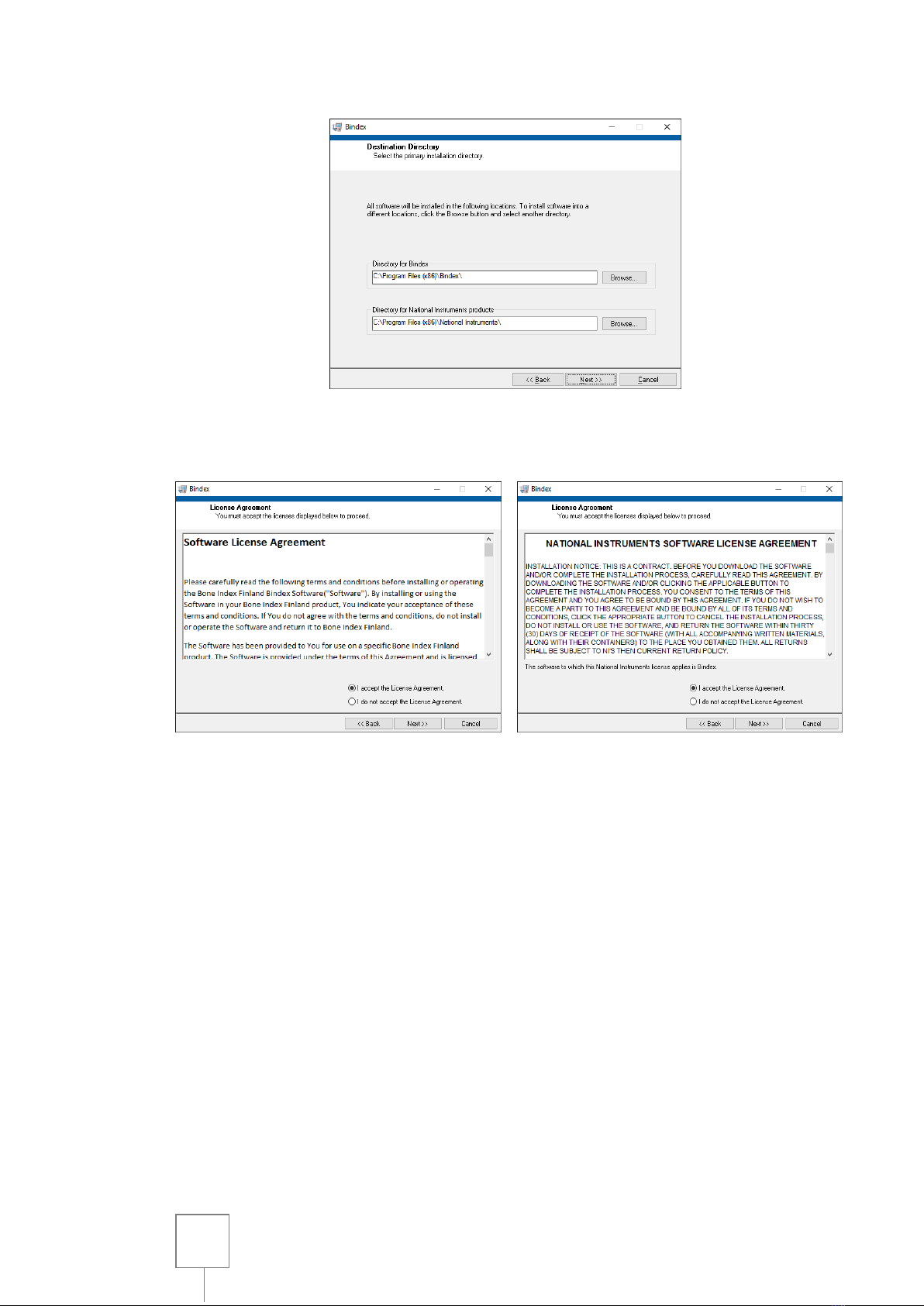
Set the installation directories in the following window (Figure 4). Please verify
the installation folder because you cannot move the software folder after installing.
The next step is accepting the license agreements (Figure 5). Carefully read the
license terms before proceeding. Selecting “I accept the License Agreement” is
required to use the Bindex Standalone Software. Press NEXT to continue. The
next window includes the license terms for the National Instruments software
required for Bindex Standalone Software. Accept the terms and click on NEXT.
Bindex® BI-2 User Manual
© Bone Index Finland Ltd.
All Rights Reserved.
19
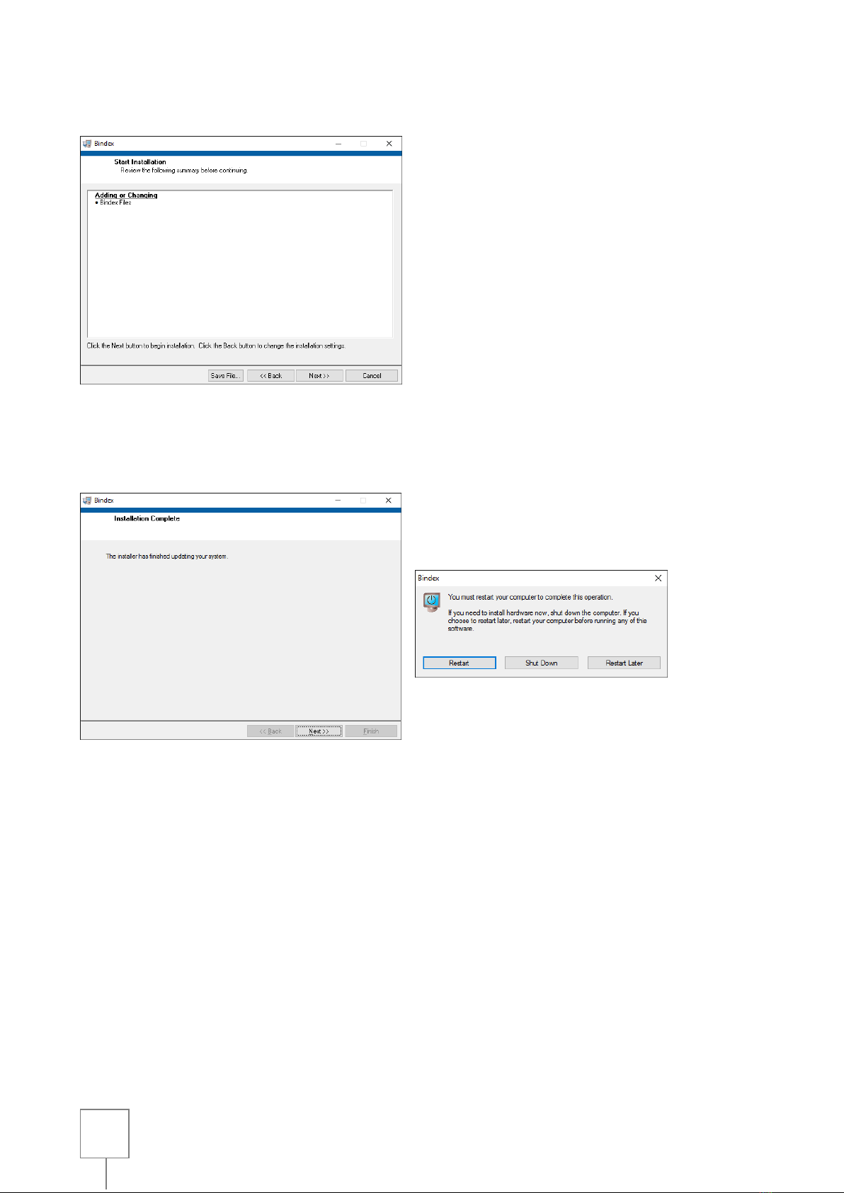
The following window (Figure 6) shows that you are about to install or change
files related to Bindex Standalone Software. The installation starts by pressing
NEXT.
After a successful installation a confirmation window is shown (Figure 7). Finish
the setup by pressing NEXT. LabVIEW Run-time Engine 7.0 and Microsoft
Access database engine 2010 are required to be installed to run Bindex Standalone
Software. The installation of these programs is automatically launched after the
Bindex installation. Please follow the instructions on the screen to complete the
setup. A restart is required to before running Bindex Standalone Software. You
may do this at this point or later.
Figure 4:
Setting the installation directories. The paths may be changed if needed.
Figure 5: The license agreements. Carefully read the terms before proceeding. After accepting
the licenses, continue with the installation by clicking on NEXT.
Bindex® BI-2 User Manual
© Bone Index Finland Ltd.
All Rights Reserved.
20
Figure 6:
Starting the installation.
Figure 7: Installation completed successfully. Exit the installation program by pressing NEXT.
After installing all required components, a restart is needed before using the software.
Other manuals for BI-2
1
Table of contents
Other Bindex Medical Equipment manuals

Popular Medical Equipment manuals by other brands

LINET
LINET Sprint 200 Instructions for use and Technical description

Haag-Streit
Haag-Streit LI 900 Instructions for use

PHILIPS Respironics
PHILIPS Respironics Wisp manual

Top shelf Orthopedics
Top shelf Orthopedics Knight OA Instructions for use

GE
GE LOGIC C2 Series Technical publication

Ormed
Ormed ARTROMOT-K4 Operation manual


ACS
ACS A1020 MIRA Lite Operation manual

BreatheSuite
BreatheSuite BreatheSuiteMDIV1 user manual

Atmos
Atmos C 051 Thorax operating instructions

Roche
Roche Accu-Chek Aviva Combo Quick reference guide

Harvest Healthcare
Harvest Healthcare OLYMPIC TURNER General User/ Safety Guide

JAS GL
JAS GL Knee Flexion Assembly instructions