tryten S Series User manual

S1/S2 Assembly Instructions –Rev N Page 2

S1/S2 Assembly Instructions –Rev N Page 3

S1/S2 Assembly Instructions –Rev N Page 4
Assembly Instructions Page
Receiving the Shipping Box 7
Assembling Pole to Base 8
Assembling Handle to Pole 8
Universal OmniTab Adjustment 9-11
Removing the Channel Strips 12
S2 Universal OmniTab Installation 12
Utility Box and Cabling Installation 13
Device Height Adjustment 14
Work Surface Installation 15
16-18
19
19
20
20
21
22-23
Supply Caddy and Small Device Holder Installation
Fixed VESA Bracket and Monitor Installation
S2 VESA Plate Installation
Wire Basket Installation
Poly SY20 Speaker Installation
Butterfly Bracket Installation
Speaker Mount Installations
Arm Travel Limiter Installation
Cleaning Guide
24
26-28

S1/S2 Assembly Instructions –Rev N Page 5
Introduction –Statement of Use
The manufacturer's goal is to elevate your performance by offering
innovative solutions that help optimize healthcare workflows and
improve patient care.
•The Tryten S1/S2 carts are designed for safe use of tablets or
monitors by clinicians or patients in general patient areas. The carts
may also have cameras, speakers and/or other devices mounted on
them.
•The Tryten S1/S2 carts are not intended for home use.
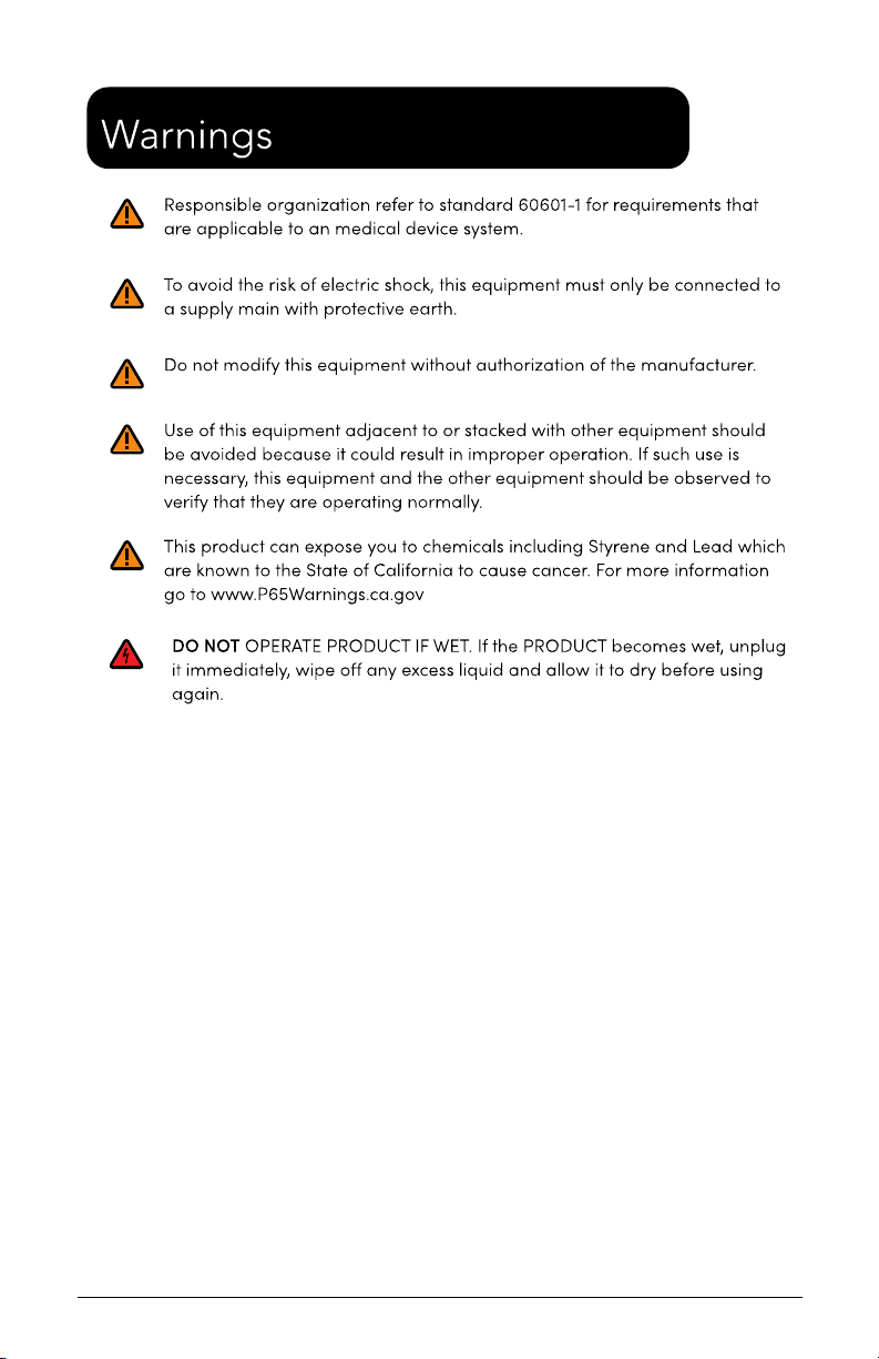
•The responsible organization shall refer to standard 60601-1;
assembly of ME SYSTEMS and modifications during the actual service
life that require evaluation to the requirements of this standard
To ensure safety, please read this manual carefully before installation and
follow the instructions herein. Store this manual in a secure place for future
reference.
The manufacturer shall not be legally responsible for any equipment
damage or personal injury caused by incorrect installation or operation
other than that covered in this manual.
While the manufacturer strives to provide complete and accurate
information, it will not be held liable for any editorial errors or omissions.
The manufacturer reserves the right to make changes to the
documentation without advanced notice to the customer.
Specifications and product attributes are subject to change without notice.

S1/S2 Assembly Instructions –Rev N Page 6
HARDWARE PACK
•Felt Pads –3/4” x 1/8” thick (6)
•Label Hardware Kit (1)
•Hex L-Key - 3/16” size (1)
•Torx Security L-Key - T25 (1)
•Hex L-Key - 5/32” size (1)
•Keys Set Tablet Cart (1)
•Screw 10-24 x 3/4" Security Torx, Button head, SS (1)
•Screw 1/4-20 by 1" Socket Head, Zinc (4)
•Belleville (dome) Washer 1/4" 18-8 SS (4)
ADDITIONAL TOOLS NEEDED FOR INSTALLATION
•Scissors for cutting channel cover to length
ASSEMBLY INSTRUCTIONS
Note: Shipping box pictures show S1 Cart for assembly reference.
Configurations may vary, but the installation process will be
similar.
INSTALLATION OF ACCESSORIES TO THE CARTS
Note: When installing accessories, the Z or T-Nut has to be loose
and aligned vertically (up/down) when inserted into the extrusion
channel. Once adjusted at the desired height, tighten the screw
until it is fully locked to the extrusion. Always verify that the nut is
aligned horizontally (left/right) when fully tightened.

S1/S2 Assembly Instructions –Rev N Page 7
1. RECEIVING THE SHIPPING BOX
•Base.
•Extract the Hardware pack, handle, and accessories
•Remove Pole Assembly from packaging.

S1/S2 Assembly Instructions –Rev N Page 8
2. ASSEMBLING POLE TO BASE
•Assemble the Pole to the base with the four (4) screws and
dome washers using the 3/16”Hex L-Key from the
Hardware Pack.
3. ASSEMBLING HANDLE TO POLE
•Assemble the Handle to the Pole using the 3/16” Hex L-Key
from the Hardware Pack.

S1/S2 Assembly Instructions –Rev N Page 9
4. A) UNIVERSAL OMNITAB ADJUSTMENT
The Universal bracket comes adjusted to fit the standard iPad 9.7
•Unlock the Top Slider using the set of keys from the
Hardware Pack. Remove the Top Slider from the Universal
Bracket.
•Loosen the three (3) screws using the 1/8”Hex L-Key from
the front of the cover.
•Pull the sliders to the appropriate size tablet.
•Tighten the three (3) adjustment screws.
•Insert tablet by sliding in from the top.
•Insert the Top Slider until it locks in the tablet and push
the locking button.

S1/S2 Assembly Instructions –Rev N Page 10
4. (B) INSTALLING 2ND SET OF SLIDERS FOR TABLET WITH
CASE
•Remove the four (4) Felt Pads from the Universal Bracket.
•Remove the four (4) screws holding the cover of the
Universal Bracket using the 1/8”Hex L-Key from the front
of the cover.
•Remove cover and the three (3) screws holding the sliders
using the 1/8”Hex L-Key from the front of the cover.

S1/S2 Assembly Instructions –Rev N Page 11
•Remove the four (4) sliders and replace with the set of
sliders from Hardware Pack.
•Install the three (3) Screws holding the sliders using the
1/8”Hex L-Key from the front of the cover.
•Put back the cover and install the four (4) screws removed
at step b) using the 1/8” Hex L-Key from the front of the
cover.
•Apply the set of felt pads supplied in the hardware pack on
top of the screws.
•Adjust sliders and install tablet, following the instructions
from Step 3A.

S1/S2 Assembly Instructions –Rev N Page 12
5. REMOVING THE CHANNEL STRIPS
•Insert one (1) of the smaller Allen L-Keys behind the top of
the channel cover to pull out of the pole. Reinstall covers
after the power cords are in place.
Note: Channel Cover Strips will need to be adjusted if
accessories are installed.
6. S2 UNIVERSAL OMNITAB INSTALLATION
•Extract the S-Series head from packaging box and the Torx
Security Button Head Screw from the Hardware Pack.
•Assemble the S-Series head as shown using the Torx
Security L-Key provided in the Hardware Pack.
•Tighten the screw until it is fully engaged.

S1/S2 Assembly Instructions –Rev N Page 13
7. UTILITY BOX AND CABLING INSTALLATION
•Install Utility box by loosening Z-Nuts, insert Z-Nuts into
extrusion channel, slide box up or down to desired height
and tighten screws.
•Open box by using Torx Security L-Key, loosen two (2)
screws from the back of the Utility Box until cover swings
open.
•Install 9’ Green Dot Hospital Grade Power Extension Cable
as shown (see middle image).
•Install tablet’s power cable through hole and up the
channel as shown.
•Close door back in place and re-install the screws from
back.
•
STORING THE POWER CORD
When the cart is not in use, or tablet is not being charged, the
extension cord should be wrapped and stored on the unit. Wrap
the cable firmly around the upper handle and lower handle cord
wraps located on the back of the unit pole.

S1/S2 Assembly Instructions –Rev N Page 14
8. DEVICE HEIGHT ADJUSTMENT
•In order to adjust the height of the surface or keyboard tray, the
handle may need to rotate to add more turns. The handle is
spring loaded so it can be rotated to a different position to
tighten the assembly. With assembly loose, move assembly to
desired height. Tighten the handle and lock the device in place
by turning the handle clockwise. If the handle cannot turn
anymore and the assembly is not yet tight, pull the handle out
(image 1), rotate counterclockwise and release handle back in
place (image 3) to tighten the assembly. Repeat process until
device is fully tightened.
Work Surface for S-Series
Keyboard & Mouse Tray

S1/S2 Assembly Instructions –Rev N Page 15
9. WORK SURFACE INSTALLATION
•Remove channel cover strip (ref. point 5).
•Remove articulating arm or tall pole with one (1) screw
using Torx Security L-Key provided in hardware pack.
•Remove extrusion adapter by removing two (2) 1/4”
screws with 3/16” Hex L-Key provided.
•Slide Work Surface down from top and secure at desired
height (ref. point 8).
•Reinstall Extrusion Adapter and Arm.

S1/S2 Assembly Instructions –Rev N Page 16
10. SUPPLY CADDY & SMALL DEVICE HOLDER INSTALLATION
The Supply Caddy and Small Device Holder each come in two (2)
parts –the Caddy/Holder and the Mounting Bracket and
Hardware to attach to the pole.
•Remove channel cover strip (ref. point 5).
•Install Caddy/Holder bracket with two (2) 1/4” Screws and
two (2) Z-Nuts as shown below with 5/32” L-Key provided
in hardware pack.
•Adjust bracket to desired height and tighten screws.
•Slide the Supply Caddy or Small Device Holder onto the
Mounting Bracket from above until it snaps in place.

S1/S2 Assembly Instructions –Rev N Page 17
10.1 LOCKABLE LID FOR SUPPLY CADDY
•Loosen Z-Nut from screw but do not remove.
•Rotate Z-Nut so it slides into the channel.
•Lower entire lid until it rests on the Caddy.
•Fasten lid to pole by using Torx Security L-Key (provided)
and turn screw until tight.

S1/S2 Assembly Instructions –Rev N Page 18
10.2 SETTING PERSONAL COMBINATION NUMBERS
•Factory combination is set at 0-0-0
•Combination must be on opening numbers prior to
resetting.
•You will find a hole on the outer ring for code reset, see
picture.
•Rotate lock until reset button comes into view.
•Push pin with paper clip or small pin and keep it pushed in.
•Set numbers to desired combination.
•Release button and your new combination is set.
To lock, rotate to ‘locked’ position, rotate one or more dials.
To unlock, rotate dials to personal combination and ‘unlock’.

S1/S2 Assembly Instructions –Rev N Page 19
11. FIXED VESA BRACKET & MONITOR INSTALLATION
•Remove channel cover strip (ref. point 5).
•Install bracket to extrusion with two (2) screws and two (2)
Z-Nuts.
Note: Ensure the thicker section of the bracket is
mounted at the top.
•Install VESA plate to bracket with four (4) button head
screws.
•Install Monitor to VESA plate with four (4) mounting
screws (not included).
12. S2 VESA PLATE INSTALLATION
•Install VESA Mount Plate to adapter with four (4) Button-
Head Screws.
•Install monitor or device to VESA Plate with four (4)
mounting screws (not included).

S1/S2 Assembly Instructions –Rev N Page 20
13. WIRE BASKET INSTALLATION
•Remove channel cover strip (ref. point 5).
•Loosen two (2) Z-Nuts but do not remove, place Z-Nuts
into the extrusion channel, move basket to desired height.
•Tighten wire basket to extrusion with two (2) screws and
two (2) Z-Nuts.
14. POLY SY20 SPEAKER INSTALLATION
•Remove channel cover strip (ref. point 5).
•Loosen T-Nut but do not remove, place T-Nut into the
extrusion channel, move bracket up or down to desired
height.
•Tighten bracket to extrusion with screw and T-Nut.
•Slide speaker back ridge into the fixed bracket, slide clamp
bracket onto speaker and align two (2) screw holes.
•Install and tighten two (2) screws.
This manual suits for next models
2
Table of contents
Other tryten Medical Equipment manuals
Popular Medical Equipment manuals by other brands

Inspiration
Inspiration Tecotherm Neo Quick setup guide

Top shelf Orthopedics
Top shelf Orthopedics TR Post-Op PCL Instructions for use

thera-Glide
thera-Glide R-505 user guide

AQUILO
AQUILO CCT1500 Operator's manual

Tanita
Tanita DC-240MA instruction manual

Otto Bock
Otto Bock 1C20 ProSymes Instructions for use